Page 3224 of 4592

RS05W±02
H01339
H01352
RS±72
± SUPPLEMENTAL RESTRAINT SYSTEMSIDE AIRBAG SENSOR ASSEMBLY
2217 Author�: Date�:
INSTALLATION
NOTICE:
�Never use SRS parts from another vehicle. When re-
placing parts, replace them with new ones.
�Never reuse the side airbag sensor assembly in-
volved in a collision when the airbag has deployed.
�Never repair a sensor in order to reuse it.
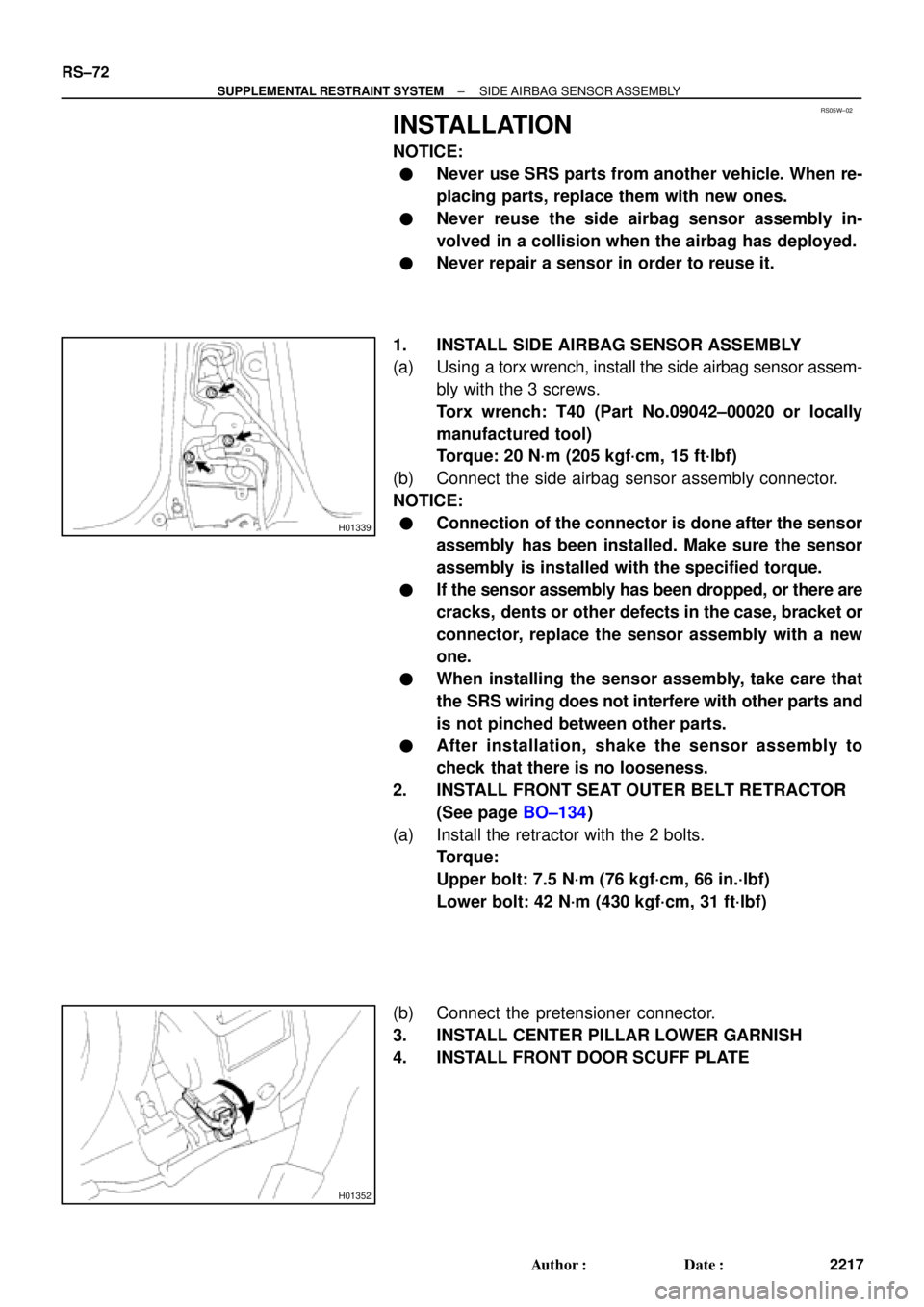
1. INSTALL SIDE AIRBAG SENSOR ASSEMBLY
(a) Using a torx wrench, install the side airbag sensor assem-
bly with the 3 screws.
Torx wrench: T40 (Part No.09042±00020 or locally
manufactured tool)
Torque: 20 N´m (205 kgf´cm, 15 ft´lbf)
(b) Connect the side airbag sensor assembly connector.
NOTICE:
�Connection of the connector is done after the sensor
assembly has been installed. Make sure the sensor
assembly is installed with the specified torque.
�If the sensor assembly has been dropped, or there are
cracks, dents or other defects in the case, bracket or
connector, replace the sensor assembly with a new
one.
�When installing the sensor assembly, take care that
the SRS wiring does not interfere with other parts and
is not pinched between other parts.
�After installation, shake the sensor assembly to
check that there is no looseness.
2. INSTALL FRONT SEAT OUTER BELT RETRACTOR
(See page BO±134)
(a) Install the retractor with the 2 bolts.
Torque:
Upper bolt: 7.5 N´m (76 kgf´cm, 66 in.´lbf)
Lower bolt: 42 N´m (430 kgf´cm, 31 ft´lbf)
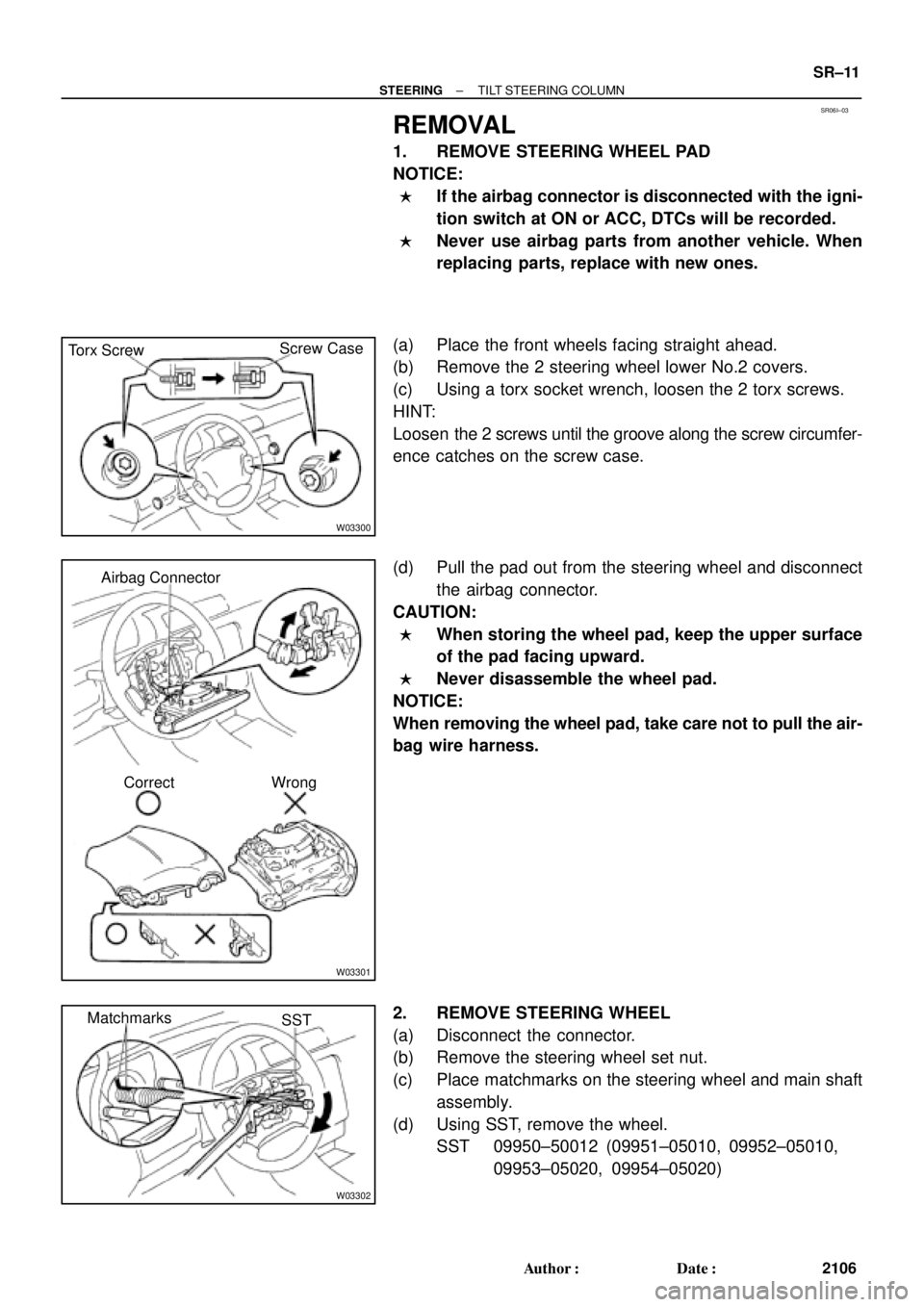
(b) Connect the pretensioner connector.
3. INSTALL CENTER PILLAR LOWER GARNISH
4. INSTALL FRONT DOOR SCUFF PLATE
Page 3225 of 4592
RS01V±11
H08282
Spiral CableCombination Meter
(Warning Light)Front Passenger Airbag Assembly
Side Airbag Assembly (RH)
Side Airbag Sensor
Assembly (RH)
Seat Belt Pretensioner (RH) Steering Wheel Pad
(with Airbag)
Side Airbag Sensor
Assembly (LH)
Seat Belt Pretensioner (LH)
Side Airbag Assembly (LH)
Airbag Sensor Assembly
Front Airbag Sensor (RH)
Front Airbag
Sensor (LH)
± SUPPLEMENTAL RESTRAINT SYSTEMWIRE HARNESS AND CONNECTOR
RS±73
2218 Author�: Date�:
WIRE HARNESS AND CONNECTOR
LOCATION
Page 3304 of 4592
SS061±17
SS±66
± SERVICE SPECIFICATIONSSUPPLEMENTAL RESTRAINT SYSTEM
229 Author�: Date�:
SUPPLEMENTAL RESTRAINT SYSTEM
TORQUE SPECIFICATION
Part tightenedN´mkgf´cmft´lbf
Steering wheel3536026
Steering wheel pad7.17263 in.´lbf
Front passenger airbag assembly x Instrument panel reinforcement2020515
Front seat installation bolt3737527
Seatback frame set bolt Bolt A
(See page RS±49) Bolt B18
15185
15013
11
Airbag sensor assembly2020515
Front airbag sensor2020515
Side airbag sensor assembly2020515
Front seat outer belt retractor Upper bolt
Lower bolt7.5
4276
43066 in.´lbf
31
Page 3307 of 4592

SS0BY±01
± SERVICE SPECIFICATIONSBODY
SS±69
232 Author�: Date�:
BODY
TORQUE SPECIFICATION
Part tightenedN´mkgf´cmft´lbf
FRONT BUMPER±±±
Front bumper cover x Body5.55549 in.´lbf
Front bumper reinforcement x Body3435025
REAR BUMPER±±±
Rear bumper cover x Body5.05043 in.´lbf
Rear bumper reinforcement x Body3435025
HOOD±±±
Hood hinge x Hood2626019
Hood lock x Body8.08071 in.´lbf
FRONT AND REAR DOOR±±±
Front door hinge x Body3131022
Rear door hinge x Body2626019
Door hinge x Door panel2626019
Door lock striker x Body2626019
Outside rear view mirror x Front door panel5.55549
Door inside handle x Door panel3.53531 in.´lbf
Door glass x Window regulator8.08071 in.´lbf
Window regulator x Door panel5.55549 in.´lbf
Door lock x Door panel5.05043 in.´lbf
Door outside handle x Door panel7.07061 in.´lbf
Door check x Body3030022
Door check x Door panel8.08071 in.´lbf
LUGGAGE COMPARTMENT DOOR AND HINGE±±±
Luggage door hinge x Luggage door8.08071 in.´lbf
Luggage door lock striker x Body5.55549 in.´lbf
Luggage door lock x Luggage door5.55549 in.´lbf
FRONT WIPER AND WASHER±±±
Wiper motor assembly x Body2424518
Wiper arm x Wiper pivot5.55549 in.´lbf
SLIDING ROOF±±±
Sliding roof assembly x Body5.55549 in.´lbf
INSTRUMENT PANEL±±±
Front passenger airbag assembly x Reinforcement2020014
Steering wheel lock nut3536026
SEAT±±±
Front Seat (Power Seat for TMC Made)±±±
Hinge cover x Seatback frame1818513
Seatback frame x Power seat adjuster1515011
Seatback frame x Side airbag assembly6.06153 in.´lbf
Front Seat (Manual Seat for TMC Made)±±±
Front seat adjuster x Body3737527
Page 3308 of 4592

SS±70
± SERVICE SPECIFICATIONSBODY
233 Author�: Date�:
Front seat inner upper track x Seat cushion1818513
Side Airbag assembly x Seatback frame1818513
Seatback assembly x Seat cushion frame6.06153 in.´lbf
Front Seat (Power Seat for TMMK Made)±±±
Side airbag assembly x Seat cushion frame6.06153 in.´lbf
Front Seat (Manual Seat for TMC Made)±±±
Side airbag assembly x Seat cushion frame6.06153 in.´lbf
Rear Seat (TMC Made)±±±
Seatback hinge x Body1818513
Rear seatback lock control x Rear seatback frame17.517812.5
Rear Seat (TMMK Made)±±±
Seatback pad (RH bolt) x Body7.87969 in.´lbf
Seatback pad (center bolt) x Body4242831
Child restraint seat x Body131309
Seatback hinge x Body1818513
Rear seatback lock control x Rear seatback frame17.517812.5
SEAT BELT±±±
Front Seat belt±±±
Shoulder anchor x Adjustable anchor4242031
Adjustable anchor x Body4242031
Inner belt x Seat4242031
Retractor x Body7.87969 in.´lbf
Floor anchor x Body4242031
Rear Seat Belt±±±
Lap outer belt anchor x Body4242031
ELR x Body4242031
Inner belt x Body4242031
Center belt x Body4242031
Page 3507 of 4592
SR06B±01
± STEERINGSTEERING SYSTEM
SR±1
2096 Author�: Date�:
STEERING SYSTEM
PRECAUTION
�Care must be taken to replace parts properly because they could affect the performance of the
steering system and result in a driving hazard.
�The CAMRY is equipped with SRS (Supplemental Restraint System) such as the driver airbag
and front passenger airbag. Failure to carry out service operation in the correct sequence could
cause the SRS to unexpectedly deployed during servicing, possibly leading to a serious acci-
dent. Before servicing (including removal or installation of parts, inspection or replacement),
be sure to read the precautionary notices in the RS section.
Page 3517 of 4592

SR06I±03
W03300
Torx ScrewScrew Case
W03301
Airbag Connector
Correct Wrong
W03302
Matchmarks
SST
± STEERINGTILT STEERING COLUMN
SR±11
2106 Author�: Date�:
REMOVAL
1. REMOVE STEERING WHEEL PAD
NOTICE:
�If the airbag connector is disconnected with the igni-
tion switch at ON or ACC, DTCs will be recorded.
�Never use airbag parts from another vehicle. When
replacing parts, replace with new ones.
(a) Place the front wheels facing straight ahead.
(b) Remove the 2 steering wheel lower No.2 covers.
(c) Using a torx socket wrench, loosen the 2 torx screws.
HINT:
Loosen the 2 screws until the groove along the screw circumfer-
ence catches on the screw case.
(d) Pull the pad out from the steering wheel and disconnect
the airbag connector.
CAUTION:
�When storing the wheel pad, keep the upper surface
of the pad facing upward.
�Never disassemble the wheel pad.
NOTICE:
When removing the wheel pad, take care not to pull the air-
bag wire harness.
2. REMOVE STEERING WHEEL
(a) Disconnect the connector.
(b) Remove the steering wheel set nut.
(c) Place matchmarks on the steering wheel and main shaft
assembly.
(d) Using SST, remove the wheel.
SST 09950±50012 (09951±05010, 09952±05010,
09953±05020, 09954±05020)
Page 3518 of 4592

W03303
Matchmarks SR±12
± STEERINGTILT STEERING COLUMN
2107 Author�: Date�:
3. REMOVE UPPER AND LOWER COLUMN COVERS
(a) Remove the lower No.2 cover from the lower cover.
(b) Remove the 3 screws.
4. REMOVE FRONT DOOR INSIDE SCUFF PLATE
5. REMOVE COWL SIDE TRIM
Remove the clip.
6. REMOVE No.1 LOWER INSTRUMENT PANEL
(a) Remove the 2 screws.
(b) Disconnect the hood lock control cable.
7. REMOVE LH LOWER INSTRUMENT PANEL
Remove the 4 bolts.
8. REMOVE LOWER INSTRUMENT FINISH PANEL
9. REMOVE COMBINATION SWITCH WITH SPIRAL
CABLE
(a) Disconnect the 3 connectors.
(b) Disconnect the airbag connector.
(c) Remove the 3 screws.
10. REMOVE SPIRAL CABLE
(See page BE±23)
NOTICE:
Do not disassemble the cable or apply oil to it.
11. DISCONNECT INTERMEDIATE SHAFT ASSEMBLY
(a) Place matchmarks on the intermediate shaft and control
valve shaft.
(b) Remove the bolt.
12. REMOVE INTERMEDIATE SHAFT ASSEMBLY
Remove the bolt.
13. REMOVE STEERING COLUMN ASSEMBLY
(a) Disconnect the connectors.
(b) Remove the 4 column assembly set nuts.