Page 3522 of 4592
 Torque the 4 column assembly set nuts.
Torque:")
SR06M±01
W03303
Matchmarks
W02655
Mark SR±16
± STEERINGTILT STEERING COLUMN
2111 Author�: Date�:
INSTALLATION
1. INSTALL STEERING COLUMN ASSEMBLY
(a) Torque the 4 column assembly set nuts.
Torque: 25 N´m (260 kgf´cm, 19 ft´lbf)
(b) Connect the connectors.
2. INSTALL INTERMEDIATE SHAFT ASSEMBLY
Torque the bolt.
Torque: 35 N´m (360 kgf´cm, 26 ft´lbf)
3. CONNECT INTERMEDIATE SHAFT ASSEMBLY
(a) Align the matchmarks on the intermediate shaft and con-
trol valve shaft.
(b) Torque the bolt.
Torque: 35 N´m (360 kgf´cm, 26 ft´lbf)
4. INSTALL SPIRAL CABLE
(See page BE±23)
5. INSTALL COMBINATION SWITCH WITH SPIRAL
CABLE
(a) Tighten the 3 screws.
(b) Connect the airbag connector.
(c) Connect the 3 connectors.
6. INSTALL LOWER INSTRUMENT FINISH PANEL
7. INSTALL LH LOWER INSTRUMENT PANEL
Tighten the 4 bolts.
8. INSTALL No.1 LOWER INSTRUMENT PANEL
(a) Connect the hood lock control cable.
(b) Tighten the 2 screws.
9. INSTALL COWL SIDE TRIM
Install the clip.
10. INSTALL FRONT DOOR INSIDE SCUFF PLATE
11. INSTALL UPPER AND LOWER COLUMN COVERS
(a) Tighten the 3 screws.
(b) Install the lower No.2 cover to the lower cover.
12. CENTER SPIRAL CABLE
(a) Check that the front wheels are facing straight ahead.
(b) Turn the cable counterclockwise by hand until it becomes
harder to turn the cable.
(c) Then rotate the cable clockwise about 3 turns to align the
mark.
HINT:
The cable will rotate about 3 turns to either left or right of the
center.
Page 3523 of 4592
W03304
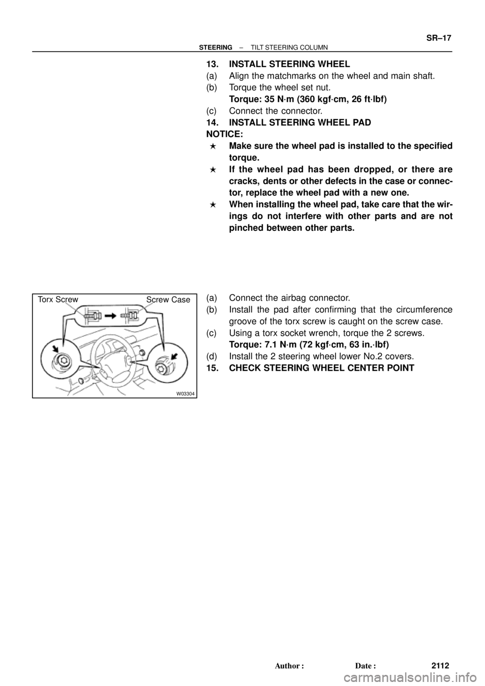
Torx Screw
Screw Case
± STEERINGTILT STEERING COLUMN
SR±17
2112 Author�: Date�:
13. INSTALL STEERING WHEEL
(a) Align the matchmarks on the wheel and main shaft.
(b) Torque the wheel set nut.
Torque: 35 N´m (360 kgf´cm, 26 ft´lbf)
(c) Connect the connector.
14. INSTALL STEERING WHEEL PAD
NOTICE:
�Make sure the wheel pad is installed to the specified
torque.
�If the wheel pad has been dropped, or there are
cracks, dents or other defects in the case or connec-
tor, replace the wheel pad with a new one.
�When installing the wheel pad, take care that the wir-
ings do not interfere with other parts and are not
pinched between other parts.
(a) Connect the airbag connector.
(b) Install the pad after confirming that the circumference
groove of the torx screw is caught on the screw case.
(c) Using a torx socket wrench, torque the 2 screws.
Torque: 7.1 N´m (72 kgf´cm, 63 in.´lbf)
(d) Install the 2 steering wheel lower No.2 covers.
15. CHECK STEERING WHEEL CENTER POINT
Page 3933 of 4592

Toyota Supports ASE CertificationPage 1 of 1
ST002±98Title:
STEERING GEAR REMOVAL/
REPLACEMENT
Models:
All Models equipped with SRS Airbag
Technical Service
BULLETIN
May 22, 1998
The following information is provided to supplement the Repair Manual procedure
for
removing/installing the steering gearbox or rack and pinion on vehicles equipped with a
driver 's side Supplemental Restraint System (SRS) Airbag.
CAUTION:
When the intermediate shaft is disconnected and the steering wheel is turned freely,
the SRS spiral cable may be broken.
Therefore, as a precaution, make sure to pass
the driver's seat belt through the steering wheel to prevent it from turning freely, as
shown below.
After working on SRS/Steering components, always check the operation of the SRS
Warning Light. Refer to the appropriate repair manual if any diagnostic trouble codes
are recorded.
Tercel, Paseo, Corolla, MR2, Celica, Camry, Avalon, Supra, Previa, Sienna, RAV4,
4Runner, Tacoma, T±100 & Land Cruiser equipped with a driver's side SRS Airbag.
1. Position the front wheels facing
straight ahead.
2. Using the driver's seat belt, set the
steering wheel so that it does not turn
(see Fig. 1).
3. Paint match marks on the
intermediate shaft and control valve
shaft (see Fig. 2).
4. Remove the intermediate shaft
retaining bolt and disconnect the
intermediate shaft (see Fig. 2).
OP CODEDESCRIPTIONTIMEOPNT1T2
N/ANot Applicable to Warranty ±±±±
STEERING
Introduction
Affected
Vehicles
Fig. 1
Repair
Procedure
Match Marks
Fig.2
Warranty
Information
Page 4020 of 4592
![TOYOTA CAMRY 1999 Service Repair Manual B
[A]: Part Code
[B]: Part Name
[C]: Part Number
Toyota Part Number are indicated.
Not all of the above part numbers of the connector are established for the supply. In case of ordering a connector
or](/manual-img/14/57448/w960_57448-4019.png "TOYOTA CAMRY 1999 Service Repair Manual B
[A]: Part Code
[B]: Part Name
[C]: Part Number
Toyota Part Number are indicated.
Not all of the above part numbers of the connector are established for the supply. In case of ordering a connector
or")
B
[A]: Part Code
[B]: Part Name
[C]: Part Number
Toyota Part Number are indicated.
Not all of the above part numbers of the connector are established for the supply. In case of ordering a connector
or terminal with wire, please confirm in advance if there is supply for it using
ªParts Catalog Newsº (published by
Parts Engineering Administration Dept.).
A 5�� ��
90980±11194
L PART NUMBER OF CONNECTORS
Code Part Name Part NumberCode Part NamePart Number
A 1
A 2
A 4
A 6
A 7A/C Ambient Temp. Sensor
A/C Condenser Fan Motor
A/C Triple Pressure SW (A/C Dual and
Single Pressure SW)
A/T Oil Temp. Sensor
ABS Actuator
ABS Actuator90980±11070
90980±11237
90980±10943
90980±11413
90980±11151D 4
D 5
D 6
D 7
D 8
D 9
D10
D11Diode (Door Courtesy Light)
Diode (Key Off Operation)
Diode (Luggage Compartment Light)
Door Lock Control Relay
Door Courtesy Light LH
Door Courtesy Light RH
Door Courtesy SW LH
Door Courtesy SW RH90980±11608
90980±10962
90980±11608
90980±10848
90980±11148
90980±11097
A 8ABS Speed Sensor Front LH
90980±10941
A 9ABS Speed Sensor Front RH
90980±11856 A10Airbag Sensor Front LH
A11Airbag Sensor Front RHD12Door Courtesy SW Front LH
90980±11156 D13Door Courtesy SW Front RH
D14Door Courtesy SW Rear LH
Door Courtesy SW Rear RH
D15
[B]�� ��[C]
A12
Auto Antenna Motor90980±11194 A 3
A/C Condenser Fan Relay90980±10940
[A]
90980±11009
90980±11002
D16
D17Door Key Lock and Unlock SW LH
Door Key Lock and Unlock SW RH90980±11170
Page 4037 of 4592

A")
G ELECTRICAL WIRING ROUTING
Position of Parts in Engine Compartment
A 1 A/C Condenser Fan Motor
A 2 A/C Magnetic Clutch and Lock Sensor
A 3 A/C Triple Pressure SW
(A/C Dual and Single Pressure SW)
A 4 ABS Actuator
A 5 ABS Actuator
A 6 ABS Speed Sensor Front LH
A 7 ABS Speed Sensor Front RH
A 8 Air Fuel Ratio Sensor
A 9 Airbag Sensor Front LH
A 10 Airbag Sensor Front RH
B 1 Brake Fluid Level Warning SW
C 1 Camshaft Position Sensor
C 2 Crankshaft Position Sensor
C 3 Cruise Control Actuator
D 1 Data Link Connector 1
E 1 Electronically Controlled Transmission Solenoid
E 2 Electronically Controlled Transmission Solenoid
E 3 Engine Coolant Temp. SensorF 1 Front Turn Signal Light and Parking Light LH
F 2 Front Turn Signal Light and Parking Light RH
F 3 Front Wiper Motor
F 4 Fuel Pressure Sensor (Delivery Pipe)
F 5 Fuel Pressure Sensor (Fuel Pipe)
F 6 Fuel Shutoff Valve (Delivery Pipe)
F 7 Fuel Shutoff Valve (Fuel Pressure Regulator)
F 8 Fuel Temp. Sensor (Delivery Pipe)
F 9 Fusible Link Block
F 10 Fusible Link Block
F 11 Fusible Link Block
F 12 Fusible Link Block
F 13 Fusible Link Block
F 14 Fusible Link Block
G 1 Generator
G 2 Generator
H 1 Headlight LH
H 2 Headlight RH
H 3 Horn (High)
H 4 Horn (Low)
Page 4039 of 4592

G ELECTRICAL WIRING ROUTING
Position of Parts in Instrument Panel
A 11 A/C Evaporator Temp. Sensor
A 12 A/C SW
A 13 ABS ECU
A 14 ABS ECU
A 15 Air Vent Mode Control Servo Motor
A 16 Airbag Squib (Front Passenger Airbag Assembly)
A 17 Airbag Squib (Steering Wheel Pad)
A 18 Ashtray Illumination
B 2 Blower Motor
B 3 Blower Resistor
B 4 Blower SW
C 4 Center Airbag Sensor Assembly
C 5 Center Airbag Sensor Assembly
C 6 Center Airbag Sensor Assembly
C 7 Cigarette Lighter
C 8 Cigarette Lighter Illumination
C 9 Clock
C 10 Combination Meter
C 11 Combination Meter
C 12 Combination Meter
C 13 Combination SW
C 14 Combination SW
C 15 Combination SW
C 16 Cruise Control ECUD 2 Data Link Connector 2
D 3 Data Link Connector 3
D 4 Diode (Courtesy)
D 5 Diode (Dome)
D 6 Diode (Idle±Up)
E 4 Engine Control Module
E 5 Engine Control Module
E 6 Engine Control Module
E 7 Engine Control Module
G 3 Glove Box Light and SW
H 5 Hazard SW
H 6 Heated Oxygen Sensor
H 7 Heater Control SW
I 9 Ignition Key Cylinder Light
I 10 Ignition SW
I 11 Integration Relay
I 12 Integration Relay
Page 4064 of 4592
FROM POWER SOURCE SYSTEM (
SEE PAGE 44)
1C 91J11
1 2
2 1
IJ2 7
IJ2 9IG3 10 IG2 1
1 I 4 I 4
A 10 A 15A 21 D10 C18 B 10B 12 B 15 C4C17 C5D3
2 1B 8
2 A
B 12 3
A
1 3
2 5 1
BR
B±YBR B±Y
BR
BR
BR
B±Y TE1
B± LL±R L±W BR
W± L W±L W± LG L±Y
G L±Y R±BR±B R±W
R±BL±W
B± R
BR
L
B±W
G± O G± O
B±YB±Y
BR
E1 +B
10A TAIL
10A
MIRROR±
HEATER (
SHIELDED)
(
SHIELDED) L
B±R
DIODE
(
IDLE±UP)
DATA LINK
CONNECTOR 1
CRANKSHAFT
POSITION SENSOR
CAMSHAFT
POSITION SENSOR
JUNCTION
CONNECTORD 1
C 2
C 1
J12
D 6
JUNCTION CONNECTOR
A/C SWHEATER CONTROL SW
POWER STEERING OIL PRESSURE SWFROM MG
CLT RELAY
FROM
A/C DUAL
PRESSURE SW
TO A/C
MAGNETIC
CLUTCH AND
LOCK SENSORJ12
P 2 H 7
A12
BR
ENGINE CONTROL MODULEB E 4 E 5ACE 6 , , D, E 7
IG1 8D 12
LL JUNCTION
CONNECTOR J 8
C 5
CENTER AIRBAG
SENSOR ASSEMBLYIG1 9
B± R
A A
4
L
TE1 NE NE± G EL S
LOCK A/CS F/PS MGC PRS LOCK IN THRPSW
A/C EVAPORATOR
TEMP. SENSOR A11
B
IG1 1
Page 4124 of 4592

SRS
NOTICE: When inspecting or repairing the SRS, perform the operation in accordance with the following precautionary
instructions and the procedure and precautions in the Repair Manual for the applicable model year.
�Malfunction symptoms of the SRS are difficult to confirm, so the DTCs become the most important source of information
when troubleshooting. When troubleshooting the SRS, always inspect the DTCs before disconnecting the battery.
�Work must be started after 90 seconds from when the ignition switch is turned to the ºLOCKº position and the
negative (±) terminal cable is disconnected from the battery.
(The SRS is equipped with a back±up power source so that if work is started within 90 seconds from
disconnecting the negative (±) terminal cable of the battery, the SRS may be deployed.)
�When the negative (±) terminal cable is disconnected from the battery, the memory of the clock and audio system will be
canceled. So before starting work, make a record of the contents memorized in the audio memory system. When work is
finished, reset the audio systems as they were before and adjust the clock. To avoid erasing the memory in each
memory system, never use a back±up power supply from outside the vehicle.
�Before repairs, remove the airbag sensor if shocks are likely to be applied to the sensor during repairs.
�Do not expose the steering wheel pad, front passenger airbag assembly, seat belt pretensioner, center airbag sensor
assembly or front airbag sensor assembly directly to hot air or flames.
�Even in cases of a minor collision where the SRS does not deploy, the steering wheel pad, front passenger airbag
assembly, seat belt pretensioner, center airbag sensor assembly and front airbag sensor assembly should be inspected.
�Never use SRS parts from another vehicle. When replacing parts, replace them with new parts.
�Never disassemble and repair the steering wheel pad, front passenger airbag assembly, seat belt pretensioner, center
airbag sensor assembly or front airbag sensor assembly in order to reuse it.
�If the steering wheel pad, front passenger airbag assembly, seat belt pretensioner, center airbag sensor assembly or
front airbag sensor assembly has been dropped, or if there are cracks, dents or other defects in the case, bracket or
connector, replace them with new ones.
�Use a volt/ohmmeter with high impedance (10 kW/V minimum) for troubleshooting the system's electrical circuits.
�Information labels are attached to the periphery of the SRS components. Follow the instructions on the notices.
�After work on the SRS is completed, perform the SRS warning light check.
�If the vehicle is equipped with a mobile communication system, refer to the precaution in the IN section of the Repair
Manual.

1C 91J11
1 2
2 1
IJ2 7
IJ2 9IG3 10 IG2 1
1 I 4 I 4
A 10 A 15A 21 D10 C18 B 10B 12 B 15 C4C17 C5D3
2 1B 8
2 A
B 12 3
A
1 3
2 5 1
BR
B±YBR B±Y
BR
BR
BR
B±Y TE1")