Page 2091 of 4592

DI08L±13
± DIAGNOSTICSCRUISE CONTROL SYSTEM
DI±879
111 4 Author�: Date�:
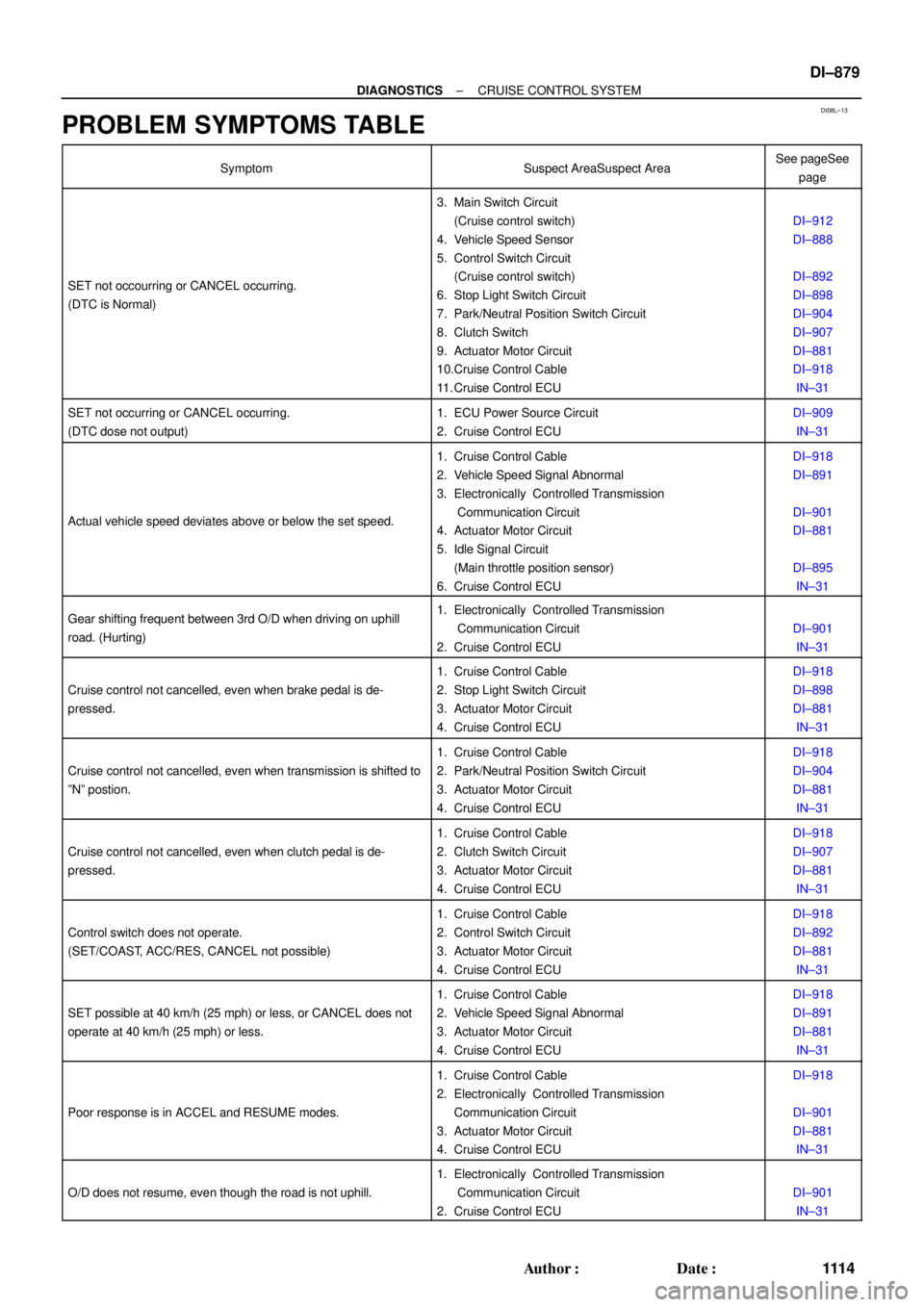
PROBLEM SYMPTOMS TABLE
SymptomSuspect AreaSuspect AreaSee pageSee
page
SET not occourring or CANCEL occurring.
(DTC is Normal)
3. Main Switch Circuit
(Cruise control switch)
4. Vehicle Speed Sensor
5. Control Switch Circuit
(Cruise control switch)
6. Stop Light Switch Circuit
7. Park/Neutral Position Switch Circuit
8. Clutch Switch
9. Actuator Motor Circuit
10.Cruise Control Cable
11. Cruise Control ECU
DI±912
DI±888
DI±892
DI±898
DI±904
DI±907
DI±881
DI±918
IN±31
SET not occurring or CANCEL occurring.
(DTC dose not output)1. ECU Power Source Circuit
2. Cruise Control ECUDI±909
IN±31
Actual vehicle speed deviates above or below the set speed.
1. Cruise Control Cable
2. Vehicle Speed Signal Abnormal
3. Electronically Controlled Transmission
Communication Circuit
4. Actuator Motor Circuit
5. Idle Signal Circuit
(Main throttle position sensor)
6. Cruise Control ECUDI±918
DI±891
DI±901
DI±881
DI±895
IN±31
Gear shifting frequent between 3rd O/D when driving on uphill
road. (Hurting)1. Electronically Controlled Transmission
Communication Circuit
2. Cruise Control ECU
DI±901
IN±31
Cruise control not cancelled, even when brake pedal is de-
pressed.
1. Cruise Control Cable
2. Stop Light Switch Circuit
3. Actuator Motor Circuit
4. Cruise Control ECUDI±918
DI±898
DI±881
IN±31
Cruise control not cancelled, even when transmission is shifted to
ºNº postion.
1. Cruise Control Cable
2. Park/Neutral Position Switch Circuit
3. Actuator Motor Circuit
4. Cruise Control ECUDI±918
DI±904
DI±881
IN±31
Cruise control not cancelled, even when clutch pedal is de-
pressed.
1. Cruise Control Cable
2. Clutch Switch Circuit
3. Actuator Motor Circuit
4. Cruise Control ECUDI±918
DI±907
DI±881
IN±31
Control switch does not operate.
(SET/COAST, ACC/RES, CANCEL not possible)
1. Cruise Control Cable
2. Control Switch Circuit
3. Actuator Motor Circuit
4. Cruise Control ECUDI±918
DI±892
DI±881
IN±31
SET possible at 40 km/h (25 mph) or less, or CANCEL does not
operate at 40 km/h (25 mph) or less.
1. Cruise Control Cable
2. Vehicle Speed Signal Abnormal
3. Actuator Motor Circuit
4. Cruise Control ECUDI±918
DI±891
DI±881
IN±31
Poor response is in ACCEL and RESUME modes.
1. Cruise Control Cable
2. Electronically Controlled Transmission
Communication Circuit
3. Actuator Motor Circuit
4. Cruise Control ECUDI±918
DI±901
DI±881
IN±31
O/D does not resume, even though the road is not uphill.
1. Electronically Controlled Transmission
Communication Circuit
2. Cruise Control ECU
DI±901
IN±31
Page 2095 of 4592

I00281
Cruise Control ECU
C15
G±B
2 1 34W±B
3
STOP Fuse8 Stop Light Switch
4
R±Y
Stop Lights Cruise Control Actuator
� Actuator Magnetic Clutch
J7
J7AAJ/C
W±B
1J
1J
W±B
A
J/C
IG 8
7
J11Instrument
Panel J/BL
± DIAGNOSTICSCRUISE CONTROL SYSTEM
DI±883
111 8 Author�: Date�:
DTC 12 Actuator Magnetic Clutch Circuit
CIRCUIT DESCRIPTION
This circuit turns on the magnetic clutch inside the actuator during cruise control operation according to the
signal from the ECU. If a malfunction occurs in the actuator or speed sensor, etc. during cruise control opera-
tion, the rotor shaft between the motor and control plate is released.
When the brake pedal is depressed, the stop light switch turns on, supplying electrical power to the stop light.
Power supply to the magnetic clutch is mechanically cut and the magnetic clutch is turned OFF.
When driving downhill, if the vehicle speed exceeds the set speed by 15 km/h (9 mph), the ECU turns the
safety magnet clutch OFF. If the vehicle speed later drops to within 10 km/h (6 mph), cruise control at the
set speed is resumed.
DTC No.Detection ItemTrouble Area
12Short in actuator magnetic clutch circuit.
Open (0.8 sec.) in actuator magnetic clutch circuit.
�STOP Fuse
�Stop light switch
�Actuator magnetic clutch
�Harness or connector between cruise control ECU and
actuator magnetic clutch, actuator magnetic clutch and body
ground
�Cruise control ECU
WIRING DIAGRAM
DI08N±12
Page 2096 of 4592
I00157
Instrument panel junction block No.1:
STOP Fuse
I00133
21
43
DI±884
± DIAGNOSTICSCRUISE CONTROL SYSTEM
111 9 Author�: Date�:
INSPECTION PROCEDURE
1 Check STOP fuse.
PREPARATION:
(a) Turn ignition switch OFF.
(b) Remove the STOP fuse from instrument panel junction
block No.1.
CHECK:
Check fuse continuity.
OK:
There is continuity.
NG Replace STOP fuse.
OK
2 Check stop light switch.
PREPARATION:
Disconnect the stop light switch connector.
CHECK:
Check continuity between terminals.
Switch positionContinuity
Switch pin free
(Brake pedal depressed)1 ± 2
Switch pin pushed in
(Brake pedal released)3 ± 4
NG Replace stop light switch.
OK
Page 2110 of 4592

I00285
Cruise Control ECU
2
STP±
8
L
J27
J/C
G±W A A
G±W 5
1R
1R
G±W 1
4 Stop Light Switch
2
3
W
7
1C4
1BG±B 4
B±R
FL BLOCK
F91 1
F4
B±G
FL MAIN
BatteryR±Y
Cruise Control
Actuator
3
4 J/C
A
J7 A
J7
W±B
1J
1JJ/C
AJ11
W±B
IG Instrument Panel J/B
STOP
ALT
C15
C15
Instrument Panel J/B
Instrument Panel J/BW±B
87 DI±898
± DIAGNOSTICSCRUISE CONTROL SYSTEM
1133 Author�: Date�:
Stop Light Switch Circuit
CIRCUIT DESCRIPTION
When the brake pedal is depressed, the stop light switch sends a signal to the ECU. When the ECU receives
this signal, it cancels the cruise control.
A fail±safe function is provided so that the cancel functions normally, even if there is a malfunction in the stop
light signal circuit.
The cancel conditions are: Battery positive voltage at terminal STP±
When the brake is ON, battery positive voltage normally is applied through the STOP fuse and stop light
switch to terminal STP± of the ECU, and the ECU turns the cruise control OFF.
If the harness connected to terminal STP± has an open circuit, terminal STP± will have battery positive volt-
age and the cruise control will be turned OFF.
Also, when the brake is ON, the magnetic clutch circuit is cut mechanically by the stop light switch, turning
the cruise control OFF. (See page DI±883 for operation of the magnetic clutch)
WIRING DIAGRAM
DI08T±11
Page 2111 of 4592
Input SignalIndicator Light
Blinking Pattern
Stop Light
switch ON
LightOFF
ONSW OFF
SW ON
± DIAGNOSTICSCRUISE CONTROL SYSTEM
DI±899
1134 Author�: Date�:
INSPECTION PROCEDURE
1 Check operation of stop light.
CHECK:
Check that stop light comes ON when brake pedal is depressed, and turns OFF when brake pedal is re-
leased.
NG Check stop light system (See page BE±2).
OK
2 Input signal check.
CHECK:
(a) See input signal check on DI±870.
(b) Check the indicator light when the brake pedal is de-
pressed.
OK:
The indicator light goes OFF when the brake pedal is
depressed.
OK Proceed to next circuit inspection shown on
problem symptoms table (See page DI±879).
NG
Page 2112 of 4592
AB0119
I00142
I00173
ON
STP±
(±) (+)
DI±900
± DIAGNOSTICSCRUISE CONTROL SYSTEM
1135 Author�: Date�:
3 Check voltage between terminal STP± of cruise control ECU connector and
body ground.
PREPARATION:
(a) Remove the ECU with connectors still connected.
(b) Turn ignition switch ON.
CHECK:
Measure voltage between terminal STP± of cruise control ECU
connector and body ground, when the brake pedal is de-
pressed and released.
OK:
Depressed10 ± 14 V
ReleasedBelow 1 V
OK Proceed to next circuit inspection shown on
problem symptoms table (See page DI±879).
NG
4 Check for open in harness and connectors between terminal STP± of cruise con-
trol ECU and stop light switch (See page IN±31).
NG Repair or replace harness or connector.
OK
Check and replace cruise control ECU
(See page IN±31).
Page 2170 of 4592

± DIAGNOSTICSENGINE
DI±19
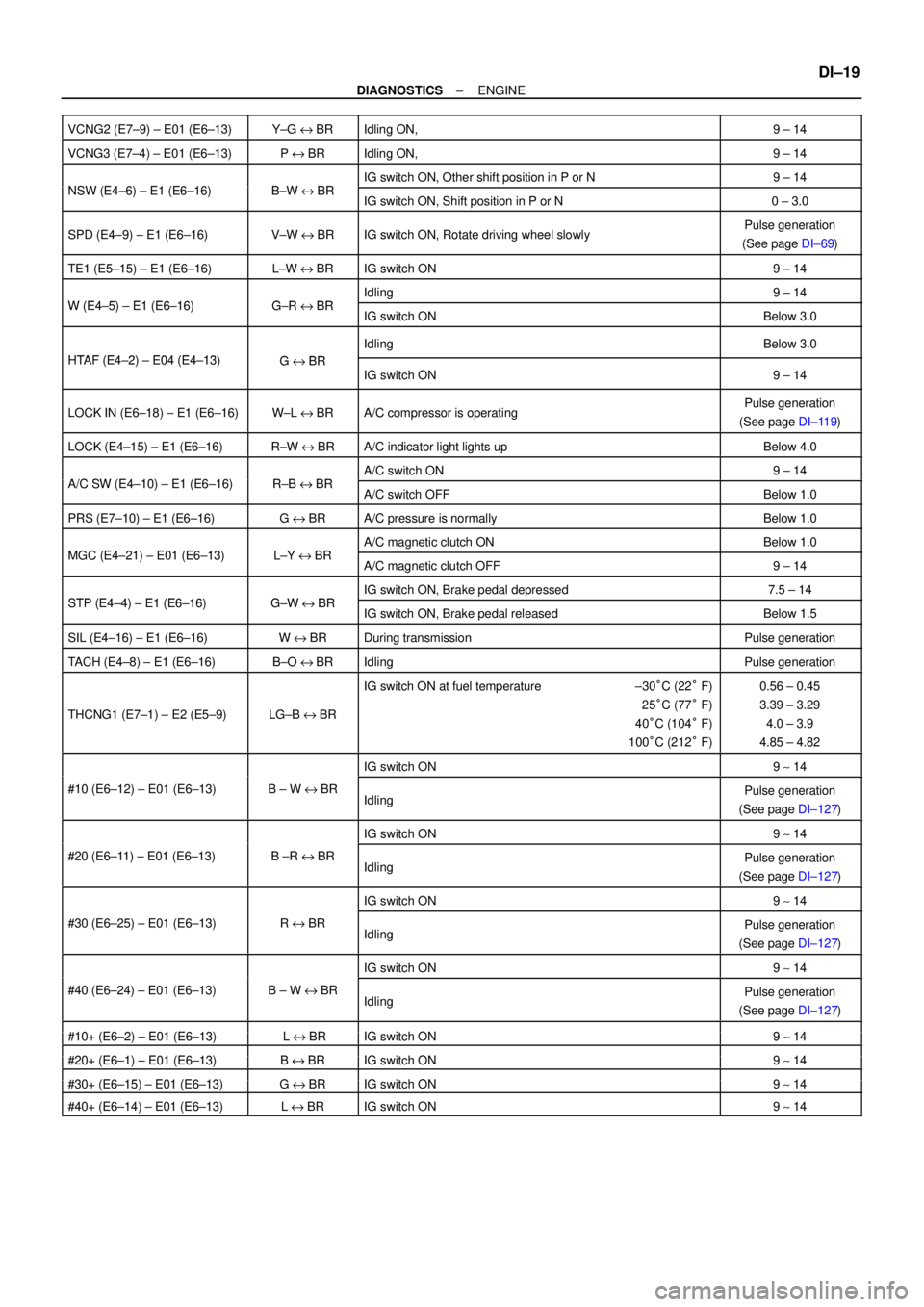
VCNG2 (E7±9) ± E01 (E6±13)Y±G e BRIdling ON,9 ± 14
VCNG3 (E7±4) ± E01 (E6±13)P e BRIdling ON,9 ± 14
NSW (E4 6) E1 (E6 16)BWBRIG switch ON, Other shift position in P or N9 ± 14NSW (E4±6) ± E1 (E6±16)B±W e BRIG switch ON, Shift position in P or N0 ± 3.0
SPD (E4±9) ± E1 (E6±16)V±W e BRIG switch ON, Rotate driving wheel slowlyPulse generation
(See page DI±69)
TE1 (E5±15) ± E1 (E6±16)L±W e BRIG switch ON9 ± 14
W (E4 5) E1 (E6 16)GRBRIdling9 ± 14W (E4±5) ± E1 (E6±16)G±R e BRIG switch ONBelow 3.0
HTAF (E4 2) E04 (E4 13)GBR
IdlingBelow 3.0
HTAF (E4±2) ± E04 (E4±13)G e BRIG switch ON9 ± 14
LOCK IN (E6±18) ± E1 (E6±16)W±L e BRA/C compressor is operatingPulse generation
(See page DI±119)
LOCK (E4±15) ± E1 (E6±16)R±W e BRA/C indicator light lights upBelow 4.0
A/C SW (E4 10) E1 (E6 16)RBBRA/C switch ON9 ± 14A/C SW (E4±10) ± E1 (E6±16)R±B e BRA/C switch OFFBelow 1.0
PRS (E7±10) ± E1 (E6±16)G e BRA/C pressure is normallyBelow 1.0
MGC (E4 21) E01 (E6 13)LYBRA/C magnetic clutch ONBelow 1.0MGC (E4±21) ± E01 (E6±13)L±Y e BRA/C magnetic clutch OFF9 ± 14
STP (E4 4) E1 (E6 16)GWBRIG switch ON, Brake pedal depressed7.5 ± 14STP (E4±4) ± E1 (E6±16)G±W e BRIG switch ON, Brake pedal releasedBelow 1.5
SIL (E4±16) ± E1 (E6±16)W e BRDuring transmissionPulse generation
TACH (E4±8) ± E1 (E6±16)B±O eBRIdlingPulse generation
THCNG1 (E7±1) ± E2 (E5±9)LG±B e BR
IG switch ON at fuel temperature ±30°C (22° F)
25°C (77° F)
40°C (104° F)
100°C (212° F)0.56 ± 0.45
3.39 ± 3.29
4.0 ± 3.9
4.85 ± 4.82
IG switch ON9 ~ 14
#10 (E6±12) ± E01 (E6±13)B ± W e BRIdlingPulse generation
(See page DI±127)
IG switch ON9 ~ 14
#20 (E6±11) ± E01 (E6±13)B ±R e BRIdlingPulse generation
(See page DI±127)
IG switch ON9 ~ 14
#30 (E6±25) ± E01 (E6±13)R e BRIdlingPulse generation
(See page DI±127)
IG switch ON9 ~ 14
#40 (E6±24) ± E01 (E6±13)B ± W e BRIdlingPulse generation
(See page DI±127)
#10 (E6 2) E01 (E6 13)LBRIG it h ON914#10+ (E6±2) ± E01 (E6±13) L e BRIG switch ON9 ~ 14
#20 (E6 1) E01 (E6 13)BBRIG it h ON914#20+ (E6±1) ± E01 (E6±13)B e BRIG switch ON9 ~ 14
#30 (E6 15) E01 (E6 13)GBRIG it h ON914#30+ (E6±15) ± E01 (E6±13)G e BRIG switch ON9 ~ 14
#40+ (E6±14) ± E01 (E6±13)L e BRIG switch ON9 ~ 14
Page 2259 of 4592

A09400
ECM
STP 4
E4
G±W G±WJ23 J24 1R 1R
1SJ27 J/C
AC Instrument Panel J/B
5
2 4
7
12
G±WLight
Failure
Sensor
Stop
Light
(LH) Stop
Light
(RH) G±R
2
52
5
W±B
W±B
BM High
Mount
Stop
Light
2
1R
A
A
J34
J/C
BL
1
W±B
Stop Light
Switch
2
BatteryW±B W
1C 7
STOP
41BInstrument
Panel J/B
B±R
B±R
F14
2 F14
1
ALT
F9MAIN
FL
FL Block
G±W
1
B±G
DI±108
± DIAGNOSTICSENGINE
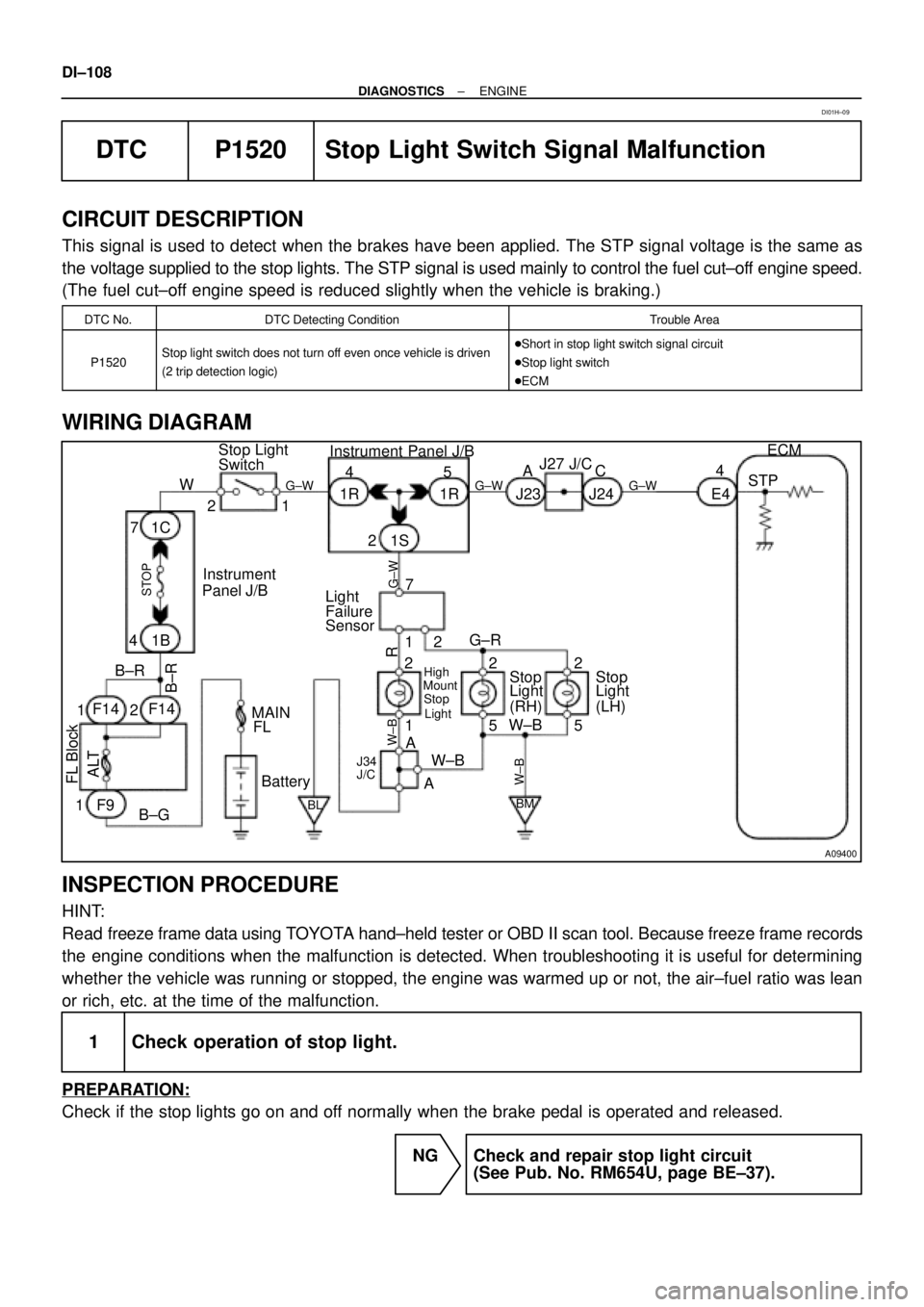
DTC P1520 Stop Light Switch Signal Malfunction
CIRCUIT DESCRIPTION
This signal is used to detect when the brakes have been applied. The STP signal voltage is the same as
the voltage supplied to the stop lights. The STP signal is used mainly to control the fuel cut±off engine speed.
(The fuel cut±off engine speed is reduced slightly when the vehicle is braking.)
DTC No.DTC Detecting ConditionTrouble Area
P1520Stop light switch does not turn off even once vehicle is driven
(2 trip detection logic)�Short in stop light switch signal circuit
�Stop light switch
�ECM
WIRING DIAGRAM
INSPECTION PROCEDURE
HINT:
Read freeze frame data using TOYOTA hand±held tester or OBD II scan tool. Because freeze frame records
the engine conditions when the malfunction is detected. When troubleshooting it is useful for determining
whether the vehicle was running or stopped, the engine was warmed up or not, the air±fuel ratio was lean
or rich, etc. at the time of the malfunction.
1 Check operation of stop light.
PREPARATION:
Check if the stop lights go on and off normally when the brake pedal is operated and released.
NG Check and repair stop light circuit
(See Pub. No. RM654U, page BE±37).
DI01H±09