Page 1060 of 4592
BR0B9±03
W03265
R00309
BR3948
R00310
BR±46
± BRAKEPARKING BRAKE
2069 Author�: Date�:
DISASSEMBLY
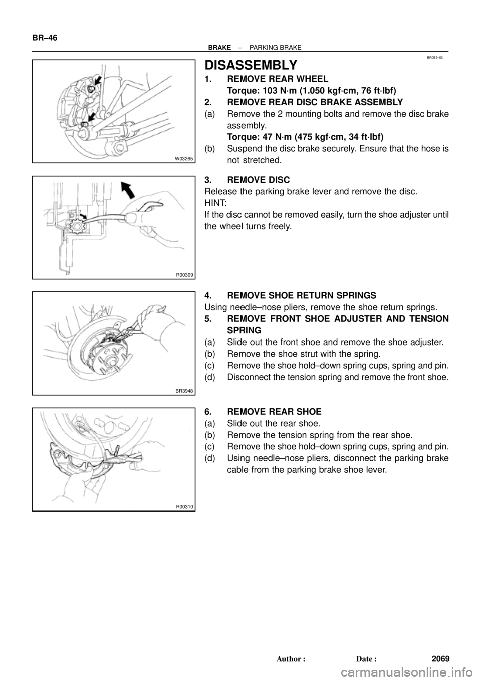
1. REMOVE REAR WHEEL
Torque: 103 N´m (1.050 kgf´cm, 76 ft´lbf)
2. REMOVE REAR DISC BRAKE ASSEMBLY
(a) Remove the 2 mounting bolts and remove the disc brake
assembly.
Torque: 47 N´m (475 kgf´cm, 34 ft´lbf)
(b) Suspend the disc brake securely. Ensure that the hose is
not stretched.
3. REMOVE DISC
Release the parking brake lever and remove the disc.
HINT:
If the disc cannot be removed easily, turn the shoe adjuster until
the wheel turns freely.
4. REMOVE SHOE RETURN SPRINGS
Using needle±nose pliers, remove the shoe return springs.
5. REMOVE FRONT SHOE ADJUSTER AND TENSION
SPRING
(a) Slide out the front shoe and remove the shoe adjuster.
(b) Remove the shoe strut with the spring.
(c) Remove the shoe hold±down spring cups, spring and pin.
(d) Disconnect the tension spring and remove the front shoe.
6. REMOVE REAR SHOE
(a) Slide out the rear shoe.
(b) Remove the tension spring from the rear shoe.
(c) Remove the shoe hold±down spring cups, spring and pin.
(d) Using needle±nose pliers, disconnect the parking brake
cable from the parking brake shoe lever.
Page 1063 of 4592
BR0BC±03
W04698
SST
SST
± BRAKEPROPORTIONING VALVE (P VALVE)
BR±49
2072 Author�: Date�:
PROPORTIONING VALVE (P VALVE)
INSPECTION
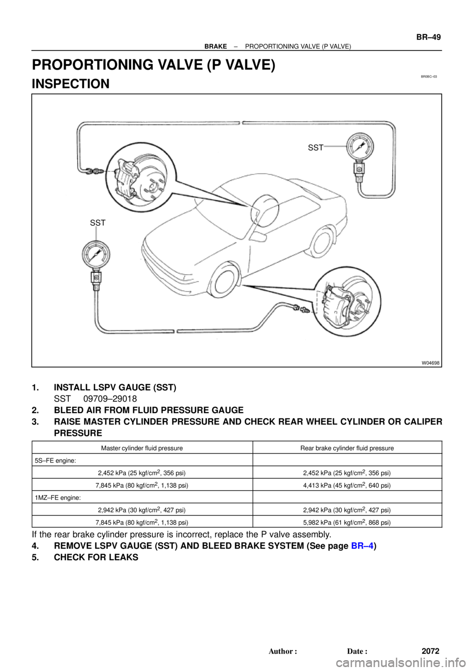
1. INSTALL LSPV GAUGE (SST)
SST 09709±29018
2. BLEED AIR FROM FLUID PRESSURE GAUGE
3. RAISE MASTER CYLINDER PRESSURE AND CHECK REAR WHEEL CYLINDER OR CALIPER
PRESSURE
Master cylinder fluid pressureRear brake cylinder fluid pressure
5S±FE engine:
2,452 kPa (25 kgf/cm2, 356 psi)2,452 kPa (25 kgf/cm2, 356 psi)
7,845 kPa (80 kgf/cm2, 1,138 psi)4,413 kPa (45 kgf/cm2, 640 psi)
1MZ±FE engine:
2,942 kPa (30 kgf/cm2, 427 psi)2,942 kPa (30 kgf/cm2, 427 psi)
7,845 kPa (80 kgf/cm2, 1,138 psi)5,982 kPa (61 kgf/cm2, 868 psi)
If the rear brake cylinder pressure is incorrect, replace the P valve assembly.
4. REMOVE LSPV GAUGE (SST) AND BLEED BRAKE SYSTEM (See page BR±4)
5. CHECK FOR LEAKS
Page 1119 of 4592

CL034±01
± CLUTCHTROUBLESHOOTING
CL±1
1780 Author�: Date�:
TROUBLESHOOTING
PROBLEM SYMPTOMS TABLE
Use the table below to help you find the cause of the problem. The numbers indicate the priority of the likely
cause of the problem. Check each part in order. If necessary, replace these parts.
SymptomSuspect AreaSee page
1. Engine mounting (Loosen)±1. Engine mounting (Loosen)
2. Clutch disc (Runout is excessive)
±
CL±17
2. Clutch disc (Runout is excessive)
3. Clutch disc (Oily)
CL±17
CL±17
Clutch grabs/chatters
3. Clutch disc (Oily)
4. Clutch disc (Worn out)
CL±17
CL±17Clutch grabs/chatters4. Clutch disc (Worn out)
5. Clutch disc torsion rubber (Damaged)
CL±17
CL±175. Clutch disc torsion rubber (Damaged)
6. Clutch disc (Glazed)
CL 17
CL±176. Clutch disc (Glazed)
7. Diaphragm spring (Out of tip alignment)
CL 17
CL±19
1. Clutch line (Air in line)±
Clutch pedal spongy
1. Clutch line (Air in line)
2. Master cylinder cup (Damaged)
±
CL±4
Clutch edal s ongy2. Master cylinder cu (Damaged)
3. Release cylinder cup (Damaged)
CL 4
CL±9
1 Release bearing (Worn dirty or damaged)CL 19Clutch noisy1. Release bearing (Worn, dirty, or damaged)
2Cl hdi i bb (D d)
CL±19
CL 17Clutch noisy2. Clutch disc torsion rubber (Damaged)CL±17
1. Clutch pedal (Freeplay out of adjustment)CL±21. Clutch edal (Free lay out of adjustment)
2. Clutch disc (Oily)
CL±2
CL±17
Cl t h li
2. Clutch disc (Oily)
3. Clutch disc (Worn out)
CL±17
CL±17Clutch slips3. Clutch disc (Worn out)
4. Diaphragm spring (Damaged)
CL 17
CL±174. Dia hragm s ring (Damaged)
5. Pressure plate (Distortion)
CL 17
CL±175. Pressure late (Distortion)
6. Flywheel (Distortion)
CL 17
±
1 Clutchpedal (Freeplay out of adjustment)CL±21. Clutch pedal (Freeplay out of adjustment)
2 Clutch line (Air in line)CL±2
2. Clutch line (Air in line)
3 Master cylinder cup(Damaged)
±
CL 43. Master cylinder cup (Damaged)
4 Release cylinder cup(Damaged)
CL±4
CL 94. Release cylinder cup (Damaged)
5 Clutch disc (out of true)
CL±9
CL 175. Clutch disc (out of true)
6 Cl tch disc (R no t is e cessi e)
CL±17
CL 17
Cl t h d t di
6. Clutch disc (Runout is excessive)
7 Cl t h di (Li i b k )
CL±17
CL 17Clutch does not disengage7. Clutch disc (Lining broken)
8 Cl t h di (Di t b d)
CL±17
CL 178. Clutch disc (Dirty or burned)
Cl h di (Oil )
CL±17
CL9. Clutch disc (Oily)CL±17
10. Clutch disc (Lack of spline grease)CL±19
11. Diaphragm spring (Damaged)CL±17gg(g)
12. Diaphragm spring (Out of tip alignment)CL±19gg( g)
13. Pressure plate (Distortion)CL±17
Page 1120 of 4592
Q10088
Pedal Height
Adjust Point
Push Rod Play
and Freeplay
Adjust Point
Push Rod Play
Pedal Height
CL035±01
CL0042
Pedal Freeplay
CL0512
25 mm (0.98 in. ) or more
Release
Point
Full Stroke
End Position CL±2
± CLUTCHCLUTCH PEDAL
1781 Author�: Date�:
CLUTCH PEDAL
INSPECTION
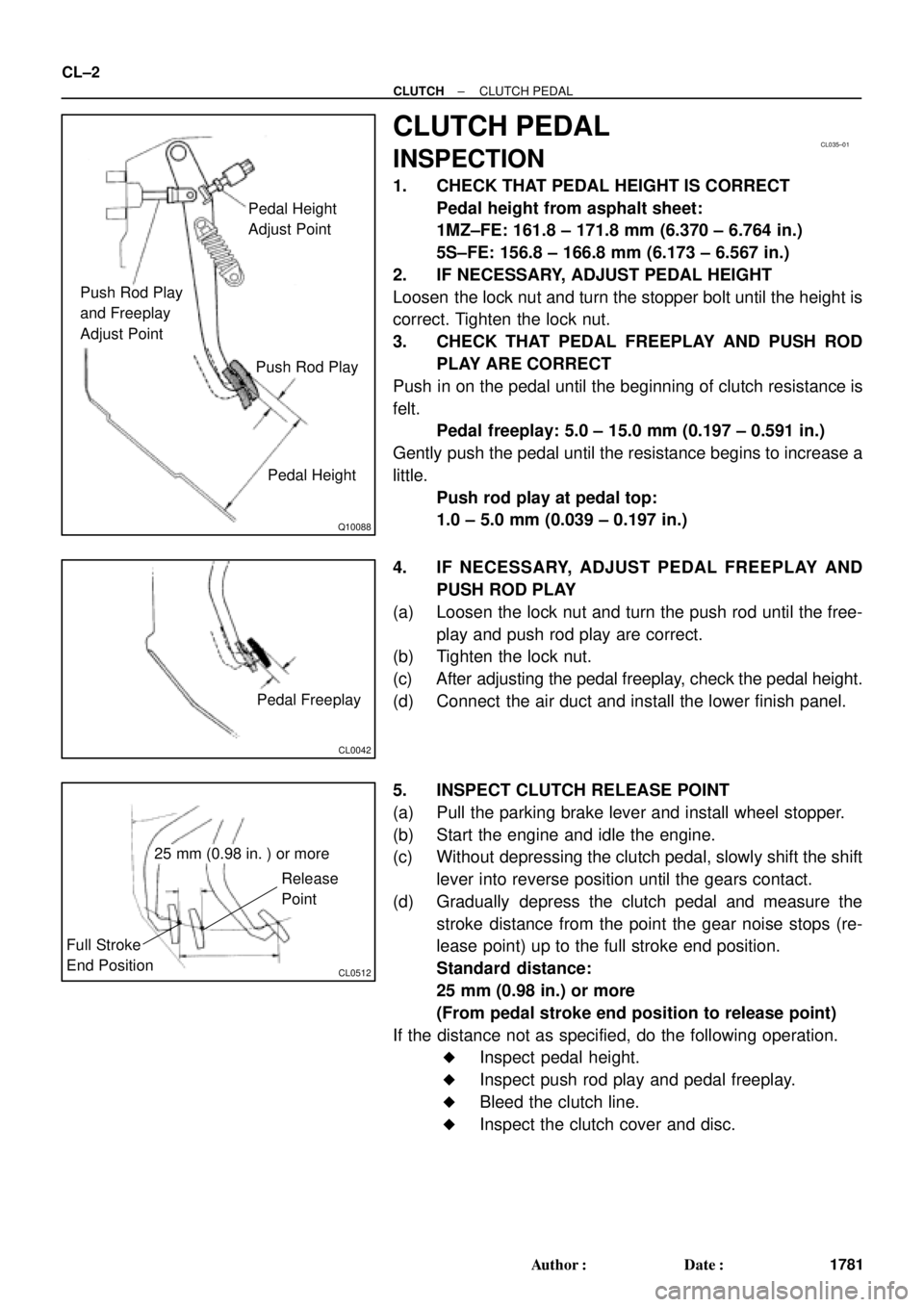
1. CHECK THAT PEDAL HEIGHT IS CORRECT
Pedal height from asphalt sheet:
1MZ±FE: 161.8 ± 171.8 mm (6.370 ± 6.764 in.)
5S±FE: 156.8 ± 166.8 mm (6.173 ± 6.567 in.)
2. IF NECESSARY, ADJUST PEDAL HEIGHT
Loosen the lock nut and turn the stopper bolt until the height is
correct. Tighten the lock nut.
3. CHECK THAT PEDAL FREEPLAY AND PUSH ROD
PLAY ARE CORRECT
Push in on the pedal until the beginning of clutch resistance is
felt.
Pedal freeplay: 5.0 ± 15.0 mm (0.197 ± 0.591 in.)
Gently push the pedal until the resistance begins to increase a
little.
Push rod play at pedal top:
1.0 ± 5.0 mm (0.039 ± 0.197 in.)
4. IF NECESSARY, ADJUST PEDAL FREEPLAY AND
PUSH ROD PLAY
(a) Loosen the lock nut and turn the push rod until the free-
play and push rod play are correct.
(b) Tighten the lock nut.
(c) After adjusting the pedal freeplay, check the pedal height.
(d) Connect the air duct and install the lower finish panel.
5. INSPECT CLUTCH RELEASE POINT
(a) Pull the parking brake lever and install wheel stopper.
(b) Start the engine and idle the engine.
(c) Without depressing the clutch pedal, slowly shift the shift
lever into reverse position until the gears contact.
(d) Gradually depress the clutch pedal and measure the
stroke distance from the point the gear noise stops (re-
lease point) up to the full stroke end position.
Standard distance:
25 mm (0.98 in.) or more
(From pedal stroke end position to release point)
If the distance not as specified, do the following operation.
�Inspect pedal height.
�Inspect push rod play and pedal freeplay.
�Bleed the clutch line.
�Inspect the clutch cover and disc.
Page 1135 of 4592
CL03J±01
Q10017
Flywheel
Clutch Disc
19 (195, 14)
47 (480, 35)
Clutch Coverx 6
Release Bearing and Hub
Release Fork5S±FE :
Release Fork
39 (400, 29)
5S±FE :
Clutch Disc
N´m (kgf´cm, ft´lbf) : Specified torqueBoot
± CLUTCHCLUTCH UNIT
CL±17
1796 Author�: Date�:
CLUTCH UNIT
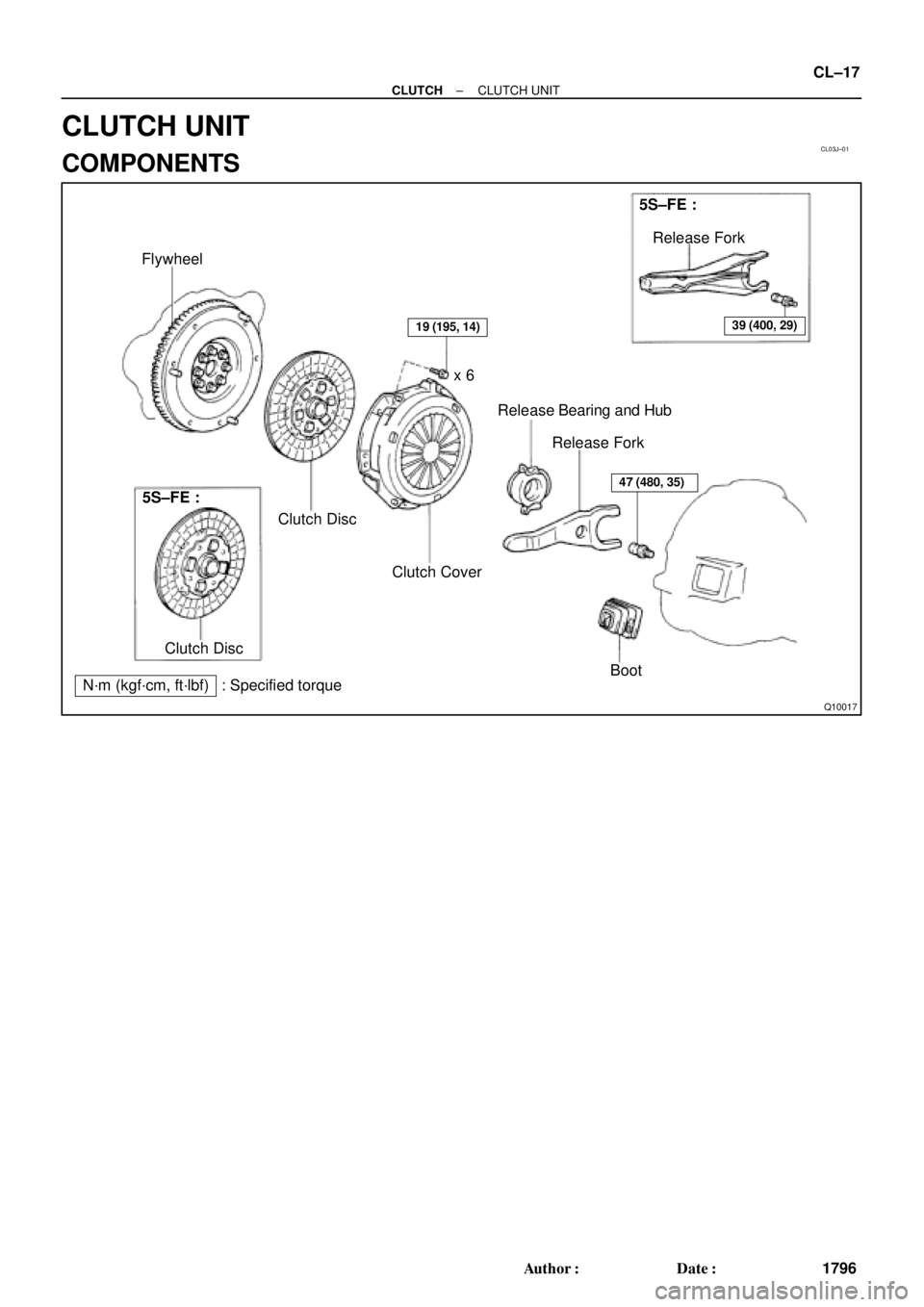
COMPONENTS
Page 1136 of 4592
CL03K±01
Q10161Matchmarks
Z19000
1MZ±FE:
5S±FE: CL±18
± CLUTCHCLUTCH UNIT
1797 Author�: Date�:
REMOVAL
1. REMOVE TRANSAXLE FROM ENGINE
(See page E153 MX±4, S51 MX±4)
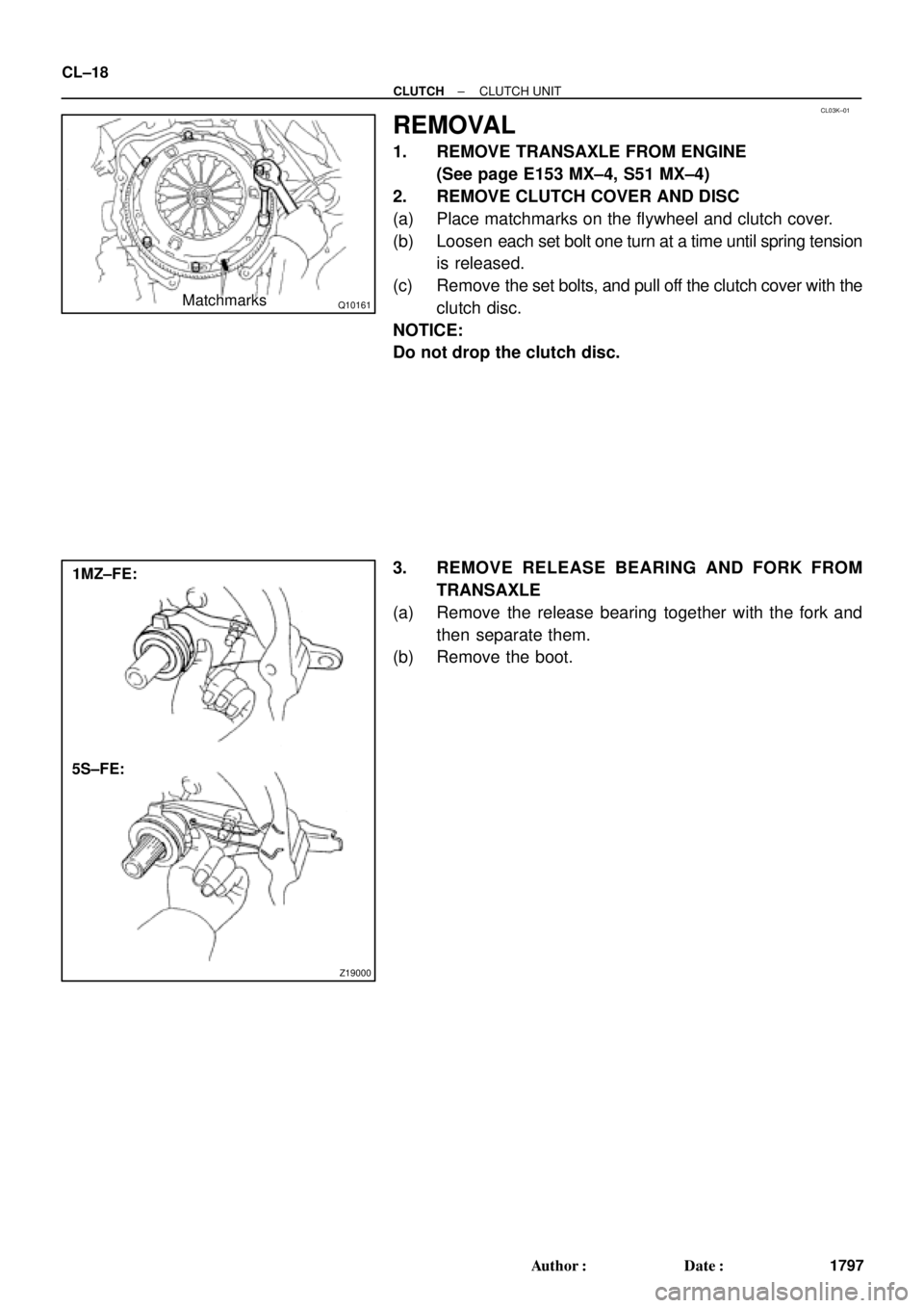
2. REMOVE CLUTCH COVER AND DISC
(a) Place matchmarks on the flywheel and clutch cover.
(b) Loosen each set bolt one turn at a time until spring tension
is released.
(c) Remove the set bolts, and pull off the clutch cover with the
clutch disc.
NOTICE:
Do not drop the clutch disc.
3. REMOVE RELEASE BEARING AND FORK FROM
TRANSAXLE
(a) Remove the release bearing together with the fork and
then separate them.
(b) Remove the boot.
Page 1137 of 4592
CL03L±01
Q10090
1MZ±FE:
5S±FE:
CL0373
CL0372
Z09915
AB
± CLUTCHCLUTCH UNIT
CL±19
1798 Author�: Date�:
INSPECTION
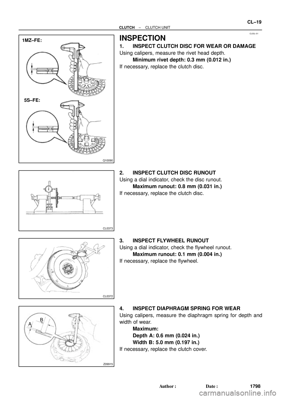
1. INSPECT CLUTCH DISC FOR WEAR OR DAMAGE
Using calipers, measure the rivet head depth.
Minimum rivet depth: 0.3 mm (0.012 in.)
If necessary, replace the clutch disc.
2. INSPECT CLUTCH DISC RUNOUT
Using a dial indicator, check the disc runout.
Maximum runout: 0.8 mm (0.031 in.)
If necessary, replace the clutch disc.
3. INSPECT FLYWHEEL RUNOUT
Using a dial indicator, check the flywheel runout.
Maximum runout: 0.1 mm (0.004 in.)
If necessary, replace the flywheel.
4. INSPECT DIAPHRAGM SPRING FOR WEAR
Using calipers, measure the diaphragm spring for depth and
width of wear.
Maximum:
Depth A: 0.6 mm (0.024 in.)
Width B: 5.0 mm (0.197 in.)
If necessary, replace the clutch cover.
Page 1139 of 4592
CL03M±02
Q10089
1MZ±FE:
5S±FE:SST
Flywheel
Side
SST
Q10084
SST
1
Matchmarks
4
2
6
35
Q10072
SST
± CLUTCHCLUTCH UNIT
CL±21
1800 Author�: Date�:
INSTALLATION
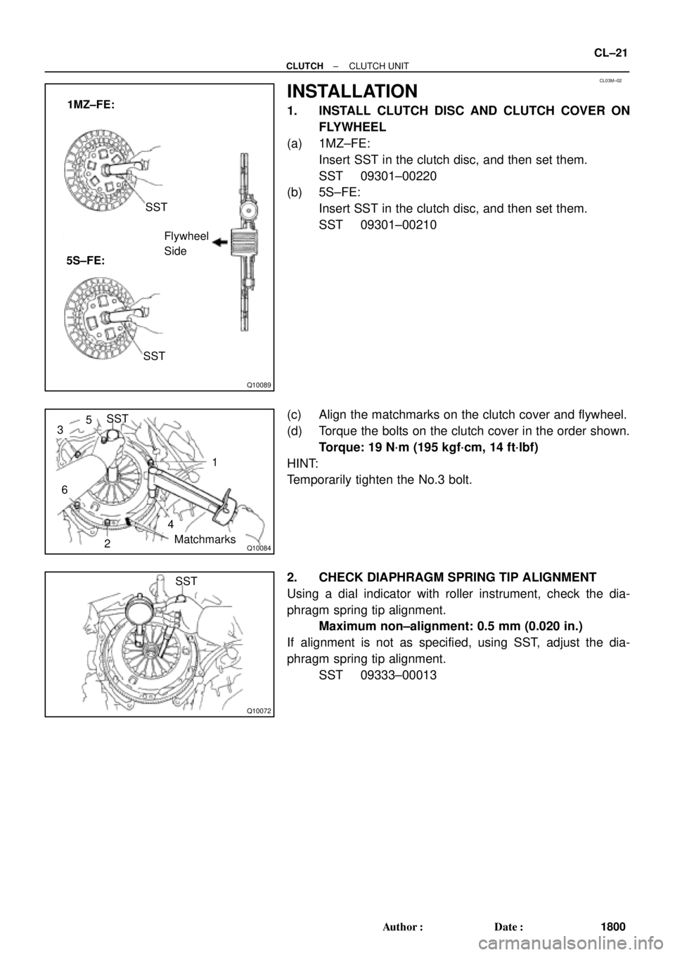
1. INSTALL CLUTCH DISC AND CLUTCH COVER ON
FLYWHEEL
(a) 1MZ±FE:
Insert SST in the clutch disc, and then set them.
SST 09301±00220
(b) 5S±FE:
Insert SST in the clutch disc, and then set them.
SST 09301±00210
(c) Align the matchmarks on the clutch cover and flywheel.
(d) Torque the bolts on the clutch cover in the order shown.
Torque: 19 N´m (195 kgf´cm, 14 ft´lbf)
HINT:
Temporarily tighten the No.3 bolt.
2. CHECK DIAPHRAGM SPRING TIP ALIGNMENT
Using a dial indicator with roller instrument, check the dia-
phragm spring tip alignment.
Maximum non±alignment: 0.5 mm (0.020 in.)
If alignment is not as specified, using SST, adjust the dia-
phragm spring tip alignment.
SST 09333±00013