Page 103 of 4592
200 mm
(7.87 in.)
± AUTOMATIC TRANSAXLE (A140E)THROTTLE CABLE
AX±9
1902 Author�: Date�:
THROTTLE CABLE
ON±VEHICLE REPAIR
1. DISCONNECT THROT")
AX039±01
Q10052
Q10339
0.8 ± 1.5 mm(0.031 ± 0.059 in.)200 mm
(7.87 in.)
± AUTOMATIC TRANSAXLE (A140E)THROTTLE CABLE
AX±9
1902 Author�: Date�:
THROTTLE CABLE
ON±VEHICLE REPAIR
1. DISCONNECT THROTTLE CABLE
(a) Disconnect the cable from the throttle linkage.
(b) Disconnect the cable from the cable clamps in the engine
compartment.
2. REMOVE PARK/NEUTRAL POSITION SWITCH
(See page AX±4)
3. REMOVE VALVE BODY (See page AX±5)
4. REMOVE THROTTLE CABLE
(a) Remove the retaining bolt and plate.
(b) Pull out the cable from the transaxle case.
5. IF THROTTLE CABLE IS NEW, STAKE STOPPER OR
PAINT MARK ON INNER CABLE
HINT:
New cable does not have a staked cable stopper.
(a) Bend the cable to ensure a radius of about 200 mm (7.87
in.).
(b) Pull the inner cable lightly until a slight resistance is felt,
and hold it there.
(c) Stake the stopper, 0.8 ± 1.5 mm (0.031 ± 0.059 in.) from
the end of the outer cable.
(d) Install a new O±ring to the throttle cable.
(e) Push in the throttle cable and install the retaining bolt.
6. INSTALL VALVE BODY (See page AX±5)
7. INSTALL PARK/NEUTRAL POSITION SWITCH
(See page AX±4)
8. CONNECT THROTTLE CABLE
9. FILL FLUID AND CHECK FLUID LEVEL
(See page DI±389)
10. ADJUST THROTTLE CABLE (See page DI±389)
Page 134 of 4592
200 mm
(7.87 in.)
± AUTOMATIC TRANSAXLE (A541E)THROTTLE CABLE
AX±13
1933 Author�: Date�:
THROTTLE CABLE
ON±VEHICLE REPAIR")
Q09982
AX03R±01
Q00225
Q00270
Q00270
Q057310.8 ± 1.5 mm (0.031±0.059 in.)200 mm
(7.87 in.)
± AUTOMATIC TRANSAXLE (A541E)THROTTLE CABLE
AX±13
1933 Author�: Date�:
THROTTLE CABLE
ON±VEHICLE REPAIR
1. REMOVE BATTERY
2. w/ Cruise Control:
REMOVE CRUISE CONTROL ACTUATOR
Remove the 3 bolts and cruise control actuator.
3. DISCONNECT THROTTLE CABLE FROM ENGINE
Disconnect the cable from the throttle linkage.
4. REMOVE PARK/NEUTRAL POSITION SWITCH
(See page AX±5)
5. REMOVE VALVE BODY
(See page AX±7)
6. REMOVE THROTTLE CABLE
(a) Remove the bolt and retaining plate.
(b) Pull out the cable from the transaxle case.
7. INSTALL THROTTLE CABLE INTO TRANSAXLE
CASE
(a) Make sure to push it in all the way.
(b) Install the retaining plate and bolt.
(c) Install and torque the bolt.
Torque: 5.4 N´m (55 kgf´cm, 48 in.´lbf)
8. INSTALL VALVE BODY
(See page AX±7)
9. IF THROTTLE CABLE IS NEW, STAKE STOPPER OR
PAINT MARK ON INNER CABLE
HINT:
New cables do not have a staked cable stopper.
(a) Bend the cable so there is a radius of about 200 mm (7.87
in.).
(b) Pull the inner cable lightly until slight resistance is felt, and
hold it there.
(c) Stake the stopper, 0.8±1.5 mm (0.031±0.059 in.) from the
end of outer cable.
Page 859 of 4592
BO0L4±01
N20966SST
N20967
BO2556
± BODYFRONT DOOR
BO±15
2363 Author�: Date�:
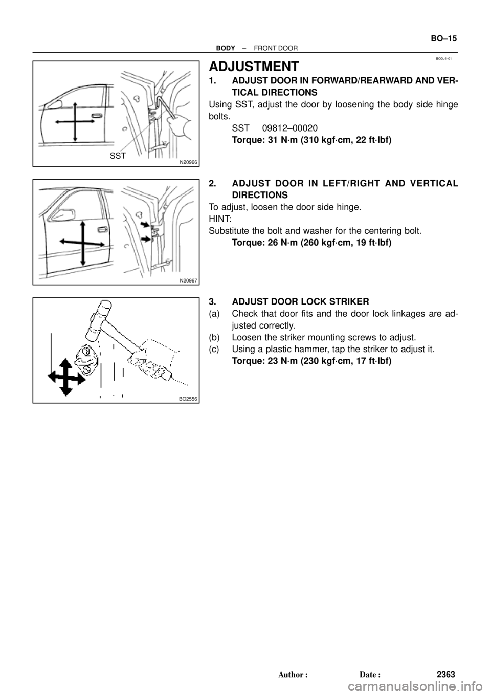
ADJUSTMENT
1. ADJUST DOOR IN FORWARD/REARWARD AND VER-
TICAL DIRECTIONS
Using SST, adjust the door by loosening the body side hinge
bolts.
SST 09812±00020
Torque: 31 N´m (310 kgf´cm, 22 ft´lbf)
2. ADJUST DOOR IN LEFT/RIGHT AND VERTICAL
DIRECTIONS
To adjust, loosen the door side hinge.
HINT:
Substitute the bolt and washer for the centering bolt.
Torque: 26 N´m (260 kgf´cm, 19 ft´lbf)
3. ADJUST DOOR LOCK STRIKER
(a) Check that door fits and the door lock linkages are ad-
justed correctly.
(b) Loosen the striker mounting screws to adjust.
(c) Using a plastic hammer, tap the striker to adjust it.
Torque: 23 N´m (230 kgf´cm, 17 ft´lbf)
Page 865 of 4592
 Remove the front part of t")
BO0L7±01
N21006
3 Clips
2 Clips
N20972
N20973
BO2556
± BODYREAR DOOR
BO±21
2369 Author�: Date�:
ADJUSTMENT
1. ADJUST DOOR IN FORWARD/REARWARD AND VER-
TICAL DIRECTION
(a) Remove the front part of the rear seat side garnish.
(b) Remove the rear part of the front door inside scuff plate.
(c) Remove the center pillar lower garnish.
HINT:
Pull both sides of the top and bottom part of the garnish out-
ward, then pull out to remove the garnish.
(d) Loosen the body side hinge nuts to adjust.
Torque: 26 N´m (260 kgf´cm, 19 ft´lbf)
(e) Install center pillar lower garnish.
(f) Install front door inside scuff plate.
(g) Install rear seat side garnish.
2. ADJUST DOOR IN LEFT/RIGHT AND VERTICAL
DIRECTIONS
Loosen the door side hinge bolts to adjust.
HINT:
Substitute a bolt with washer for the centering bolt.
Torque: 26 N´m (260 kgf´cm, 19 ft´lbf)
3. ADJUST DOOR LOCK STRIKER
(a) Check that the door fit and door lock linkages are adjusted
correctly.
(b) Loosen the striker mounting screws to adjust.
Torque: 23 N´m (230 kgf´cm, 17 ft´lbf)
(c) Using a plastic hammer, tap the striker to adjust it.
Page 2930 of 4592
 Check the steering wheel freeplay. (See page SR±8)
(b) Check the steering linkage fo")
MA00N±01
N01022
± MAINTENANCECHASSIS
MA±7
50 Author�: Date�:
CHASSIS
INSPECTION
1. INSPECT STEERING LINKAGE
(a) Check the steering wheel freeplay. (See page SR±8)
(b) Check the steering linkage for looseness or damage.
Check that:
�Tie rod ends do not have excessive play.
�Dust seals and boots are not damaged.
�Boot clamps are not loose.
2. INSPECT SRS AIRBAG (See page RS±2)
3. INSPECT STEERING GEAR HOUSING OIL
Check the steering gear housing for oil leakage.
4. INSPECT DRIVE SHAFT BOOTS
Check the drive shaft boots for clamp looseness, leakage or
damage.
5. INSPECT BALL JOINTS AND DUST COVERS
(a) Inspect the ball joints for excessive looseness.
�Jack up the front of the vehicle and place wooden
blocks with a height of 180 ± 200 mm (7.09 ± 7.87
in.) under the front tires.
�Lower the jack until there is about half a load on the
front coil spring. Place stands under the vehicle for
safety.
�Check that the front wheels are pointing straight
ahead, and block them with chocks.
�Using a lever, pry up the end of the lower arm, and
check the amount of play.
Maximum ball joint vertical play: 0 mm (0 in.)
If there is play, replace the ball joint.
(b) Check the dust cover for damage.
6. CHECK TRANSAXLE OIL (FLUID)
(a) Visually check the transaxle for oil (fluid) leakage.
If leakage is found, check for the cause and repair.
7. REPLACE TRANSAXLE OIL (FLUID)
(a) M/T:
Replace the transaxle oil.
S51: (See page MX±4)
E153: (See page MX±4)
(b) A/T:
Replace the transaxle fluid.
A140E: (See page DI±389)
A541E: (See page DI±438)
Page 3351 of 4592
THROTTLE BODY
SF±29
1462 Author�: Date�:
THROTTLE BODY
ON±VEHICLE INSPECTION
1. INSPECT THROTTLE B")
B01277
Move
SF0DN±03
B00525
P
R
E
B01278
Disconnect
Vacuum
B01282
VTA
E2
VCOhmmeter
± SFI (5S±FE)THROTTLE BODY
SF±29
1462 Author�: Date�:
THROTTLE BODY
ON±VEHICLE INSPECTION
1. INSPECT THROTTLE BODY
(a) Check that the throttle linkage moves smoothly.
(b) Check the vacuum at each port.
�Start the engine.
�Check the vacuum with your finger.
Port nameAt idleOther than idle
Mark EVacuumVacuum
Mark PNo vacuumVacuum
Mark RNo vacuumNo vacuum
2. INSPECT THROTTLE POSITION SENSOR
(a) Disconnect the sensor connector.
(b) Disconnect the vacuum hose from the throttle opener.
(c) Apply vacuum to the throttle opener.
(d) Using an ohmmeter, measure the resistance between
each terminal.
Clearance between
lever and stop screwBetween
terminalsResistance
0 mm (0 in.)VTA ± E20.2 ± 5.7 kW
Throttle valve fully
openVTA ± E22.0 ± 10.2 kW
±VC ± E22.5 ± 5.9 kW
(e) Reconnect the vacuum hose to the throttle opener.
(f) Reconnect the sensor connector.
3. INSPECT THROTTLE OPENER
(a) Allow the engine to warm up to normal operating tempera-
ture.
Page 3425 of 4592
THROTTLE BODY
SF±37
1536 Author�: Date�:
THROTTLE BODY
ON±VEHICLE INSPECTION
1. INSPECT THROTTLE BODY
Check th")
S04593
SF07T±03
S04536
Vacuum
VTAOhmmeter
E2
VC
S04604
Plug
Disconnect
± SFI (1MZ±FE)THROTTLE BODY
SF±37
1536 Author�: Date�:
THROTTLE BODY
ON±VEHICLE INSPECTION
1. INSPECT THROTTLE BODY
Check that the throttle linkage moves smoothly.
2. INSPECT THROTTLE POSITION SENSOR
(a) Disconnect the sensor connector.
(b) Disconnect the vacuum hose from the throttle body.
(c) Apply vacuum to the throttle opener.
(d) Using an ohmmeter, measure the resistance between
each terminal.
Resistance:
Throttle valve
conditionBetween
terminalsResistance
Fully closedVTA ± E20.2 ± 6.3 kW
Fully openVTA ± E22.0 ± 10.2 kW
±VC ± E22.5 ± 5.9 kW
(e) Reconnect the vacuum hose to the throttle body.
(f) Reconnect the sensor connector.
3. INSPECT THROTTLE OPENER
(a) Allow the engine to warm up to normal operating tempera-
ture.
(b) Check idle speed.
Idle speed: 700 ± 50 rpm
(c) Disconnect the vacuum hose from the throttle opener,
and plug the hose end.
(d) Check the throttle opener setting speed.
Throttle opener setting speed: 900 ± 1,950 rpm
If the throttle opener setting is not as specified, replace the
throttle body.
(e) Stop the engine.
(f) Reconnect the vacuum hose to the throttle opener.
(g) Start the engine and check that the idle speed returns to
the correct speed.
Page 3557 of 4592

SA077±01
± SUSPENSION AND AXLETROUBLESHOOTING
SA±1
1952 Author�: Date�:
TROUBLESHOOTING
PROBLEM SYMPTOMS TABLE
Use the table below to help you find the cause of the problem. The numbers indicate the priority of the likely
cause of the problem. Check each part in order. If necessary, replace these parts.
SymptomSuspect AreaSee page
Wander/pulls
1. Tire (Worn or improperly inflated)
2. Wheel alignment (Incorrect)
3. Steering linkage (Loosen or worn)
4. Hub bearings (Worn)
5. Suspension parts (Worn)
6. Steering gear (Out of adjustment or broken)SA±2
SA±4
SA±7
±
SA±10
±
±
Bottoming
1. Vehicle (Overloaded)
2. Spring (Weak)
3. Shock absorber (Worn)±
SA±33
SA±56
SA±33
SA±56
Sways/pitches
1. Tire (Worn or improperly inflated)
2. Stabilizer bar (Bent or broken)
3. Shock absorber (Worn)SA±2
SA±47
SA±69
SA±33
SA±56
Front wheel shimmy
1. Tire (Worn or improperly inflated)
2. Wheels (Out of balance)
3. Shock absorber (Worn)
4. Wheel alignment (Incorrect)
5. Ball joints (Worn)
6. Hub bearings (Worn)
7. Steering linkage (Loosen or worn)
8. Steering gear (Out of adjustment or broken)SA±2
SA±2
SA±33
SA±56
SA±4
SA±7
SA±43
SA±10
±
±
Abnormal tire wear
1. Tire (Worn or improperly inflated)
2. Wheels (Out of balance)
3. Suspension parts (Worn)
4. Shock absorber (Worn)SA±2
SA±2
±
SA±33
SA±56