Page 919 of 4592
BO0MC±01
N20987
N21123
± BODYINSTRUMENT PANEL
BO±75
2423 Author�: Date�:
REMOVAL
1. REMOVE THESE PARTS:
HINT:
Tape a screwdriver tip before use.
(a) Front door inside scuff plates
(b) Cowl side trims
(c) Front pillar garnishes
(d) Front door opening covers
(e) Lower finish plate
2. REMOVE STEERING WHEEL
(See page SR±11)
3. REMOVE STEERING COLUMN COVERS
(a) Remove the steering tilt handle.
(b) Remove the 3 screws, then the upper and lower column
covers.
4. REMOVE COMBINATION SWITCH
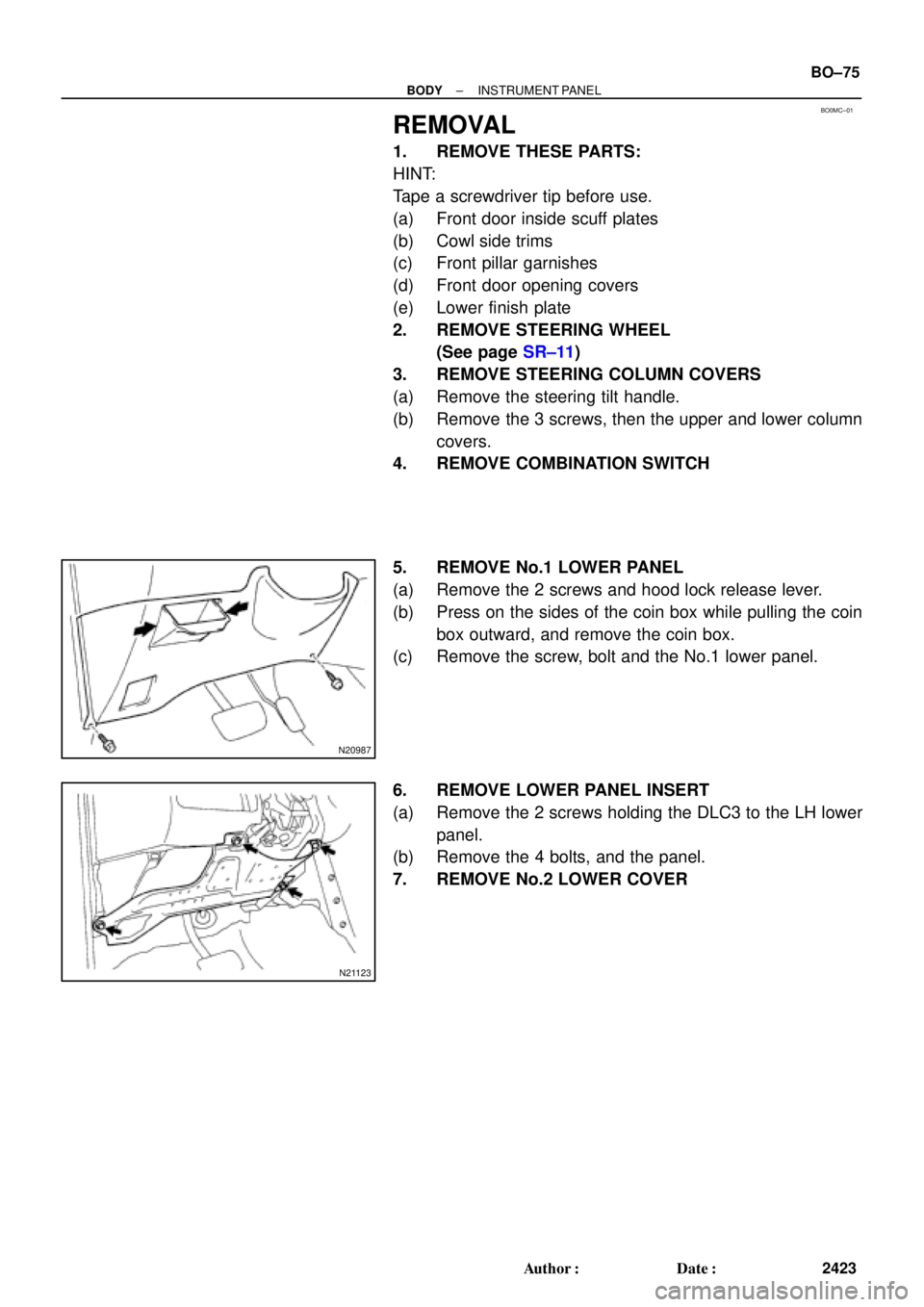
5. REMOVE No.1 LOWER PANEL
(a) Remove the 2 screws and hood lock release lever.
(b) Press on the sides of the coin box while pulling the coin
box outward, and remove the coin box.
(c) Remove the screw, bolt and the No.1 lower panel.
6. REMOVE LOWER PANEL INSERT
(a) Remove the 2 screws holding the DLC3 to the LH lower
panel.
(b) Remove the 4 bolts, and the panel.
7. REMOVE No.2 LOWER COVER
Page 976 of 4592
AB0158
SSTBattery
H01880
SST SST
H01881SST SST
± BODYSEAT BELT PRETENSIONER
BO±131
2479 Author�: Date�:
2. DEPLOYMENT WHEN DISPOSING OF FRONT SEAT
OUTER BELT ONLY
NOTICE:
�When disposing of the front seat outer belt (with seat
belt pretensioner) only, never use the customer's ve-
hicle to deploy the seat belt pretensioner.
�Be sure to following the procedure given below when
deploying the seat belt pretensioner.
HINT:
Have a battery ready as the power source when deploying the
seat belt pretensioner.
(a) Remove the front seat outer belt
(See page BO±123)
HINT:
Cut the belt near the seat belt retractor.
(b) Check functioning of SST.
(See step 1±(a))
SST 09082±00700, 09082±00740
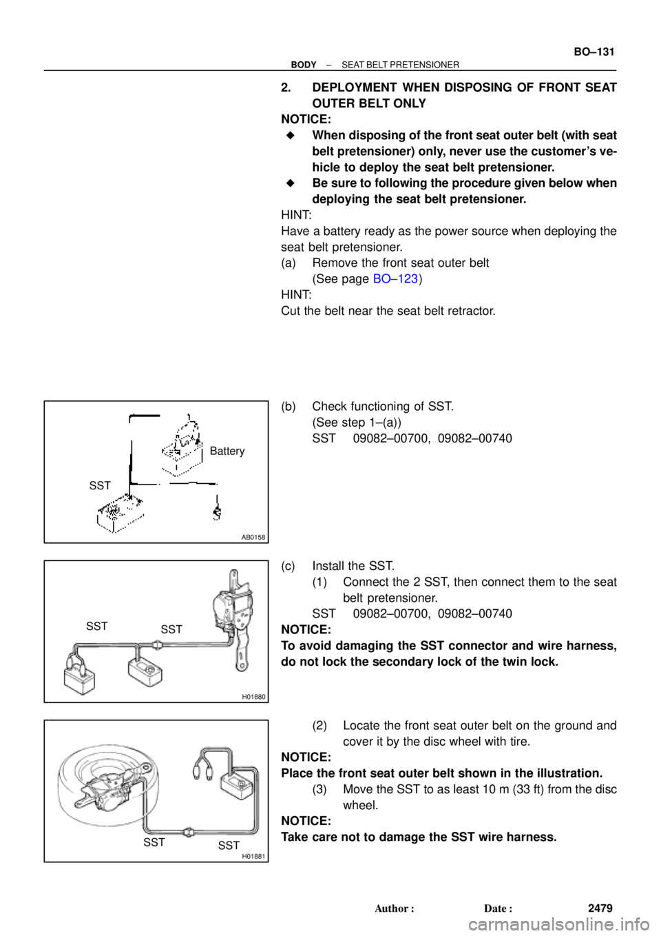
(c) Install the SST.
(1) Connect the 2 SST, then connect them to the seat
belt pretensioner.
SST 09082±00700, 09082±00740
NOTICE:
To avoid damaging the SST connector and wire harness,
do not lock the secondary lock of the twin lock.
(2) Locate the front seat outer belt on the ground and
cover it by the disc wheel with tire.
NOTICE:
Place the front seat outer belt shown in the illustration.
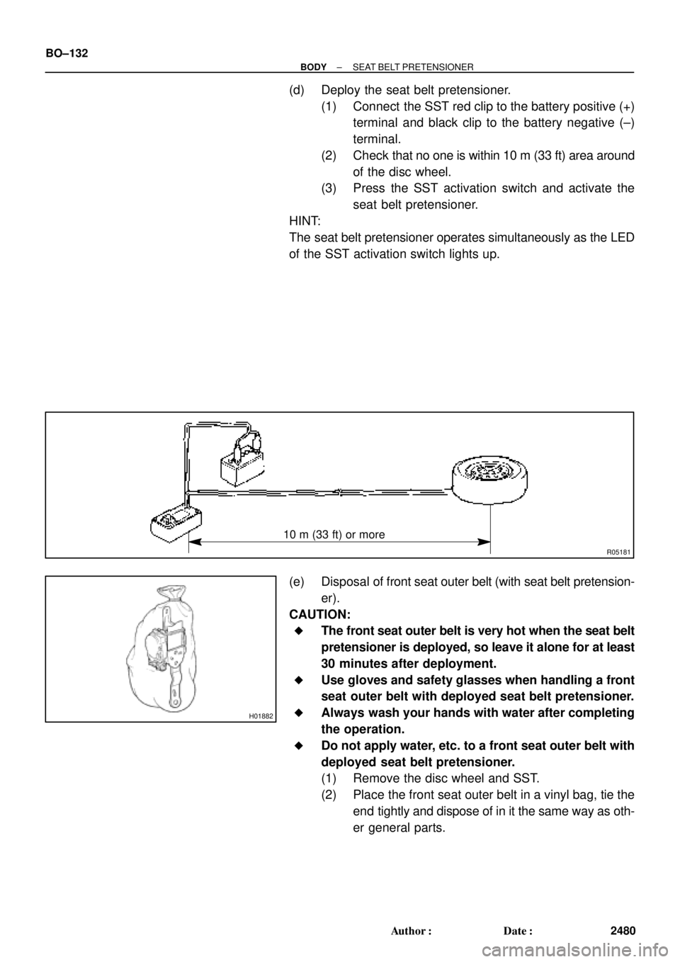
(3) Move the SST to as least 10 m (33 ft) from the disc
wheel.
NOTICE:
Take care not to damage the SST wire harness.
Page 977 of 4592
R05181
10 m (33 ft) or more
H01882
BO±132
± BODYSEAT BELT PRETENSIONER
2480 Author�: Date�:
(d) Deploy the seat belt pretensioner.
(1) Connect the SST red clip to the battery positive (+)
terminal and black clip to the battery negative (±)
terminal.
(2) Check that no one is within 10 m (33 ft) area around
of the disc wheel.
(3) Press the SST activation switch and activate the
seat belt pretensioner.
HINT:
The seat belt pretensioner operates simultaneously as the LED
of the SST activation switch lights up.
(e) Disposal of front seat outer belt (with seat belt pretension-
er).
CAUTION:
�The front seat outer belt is very hot when the seat belt
pretensioner is deployed, so leave it alone for at least
30 minutes after deployment.
�Use gloves and safety glasses when handling a front
seat outer belt with deployed seat belt pretensioner.
�Always wash your hands with water after completing
the operation.
�Do not apply water, etc. to a front seat outer belt with
deployed seat belt pretensioner.
(1) Remove the disc wheel and SST.
(2) Place the front seat outer belt in a vinyl bag, tie the
end tightly and dispose of in it the same way as oth-
er general parts.
Page 990 of 4592
BO2DN±01
H09249
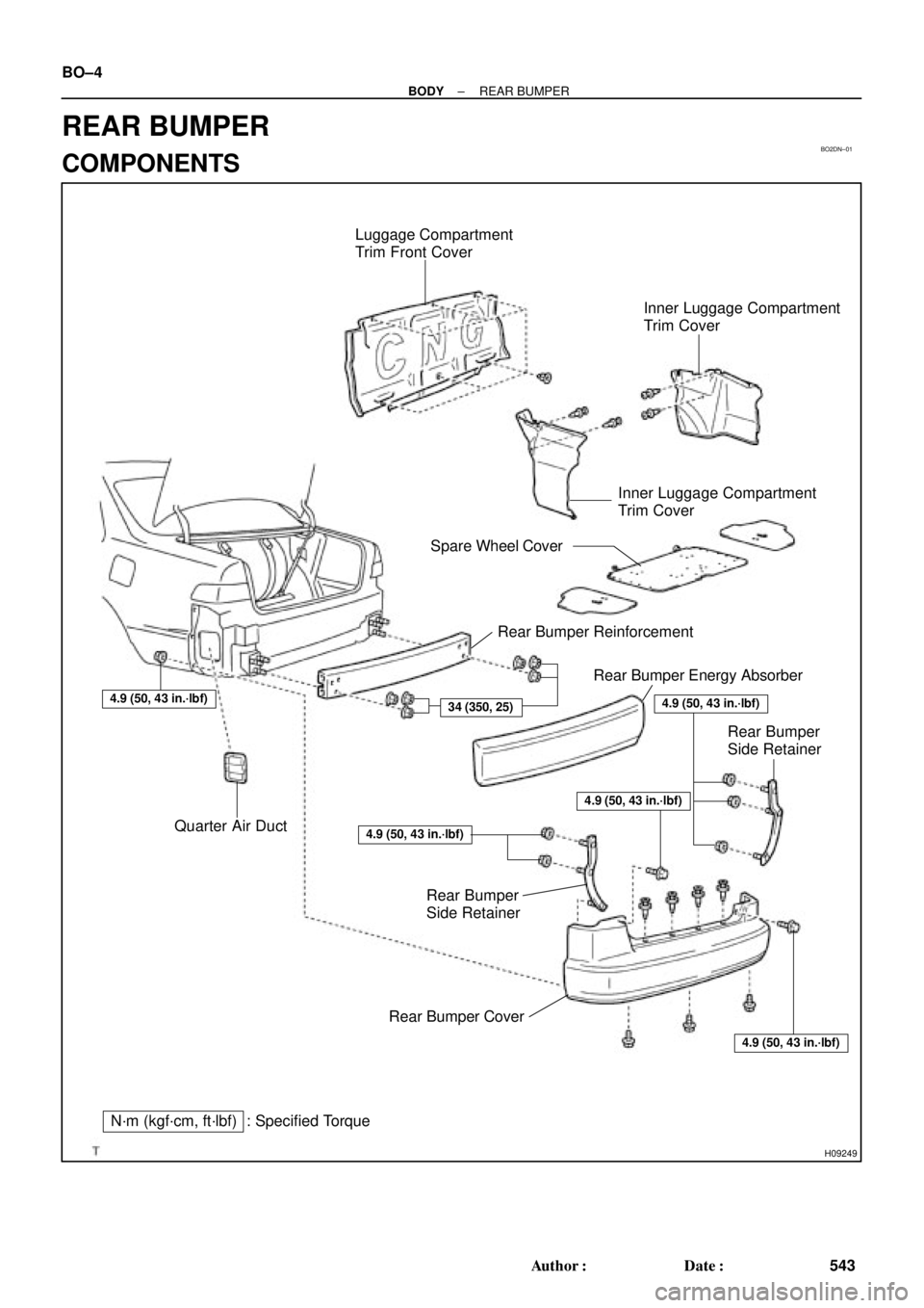
Luggage Compartment
Trim Front Cover
Rear Bumper Reinforcement
Rear Bumper Energy Absorber
Rear Bumper
Side Retainer
Quarter Air Duct
Rear Bumper Cover Rear Bumper
Side RetainerInner Luggage Compartment
Trim Cover
34 (350, 25)
4.9 (50, 43 in.´lbf)
4.9 (50, 43 in.´lbf)
N´m (kgf´cm, ft´lbf) : Specified TorqueInner Luggage Compartment
Trim Cover
Spare Wheel Cover
4.9 (50, 43 in.´lbf)
4.9 (50, 43 in.´lbf)
4.9 (50, 43 in.´lbf)
BO±4
± BODYREAR BUMPER
543 Author�: Date�:
REAR BUMPER
COMPONENTS
Page 991 of 4592
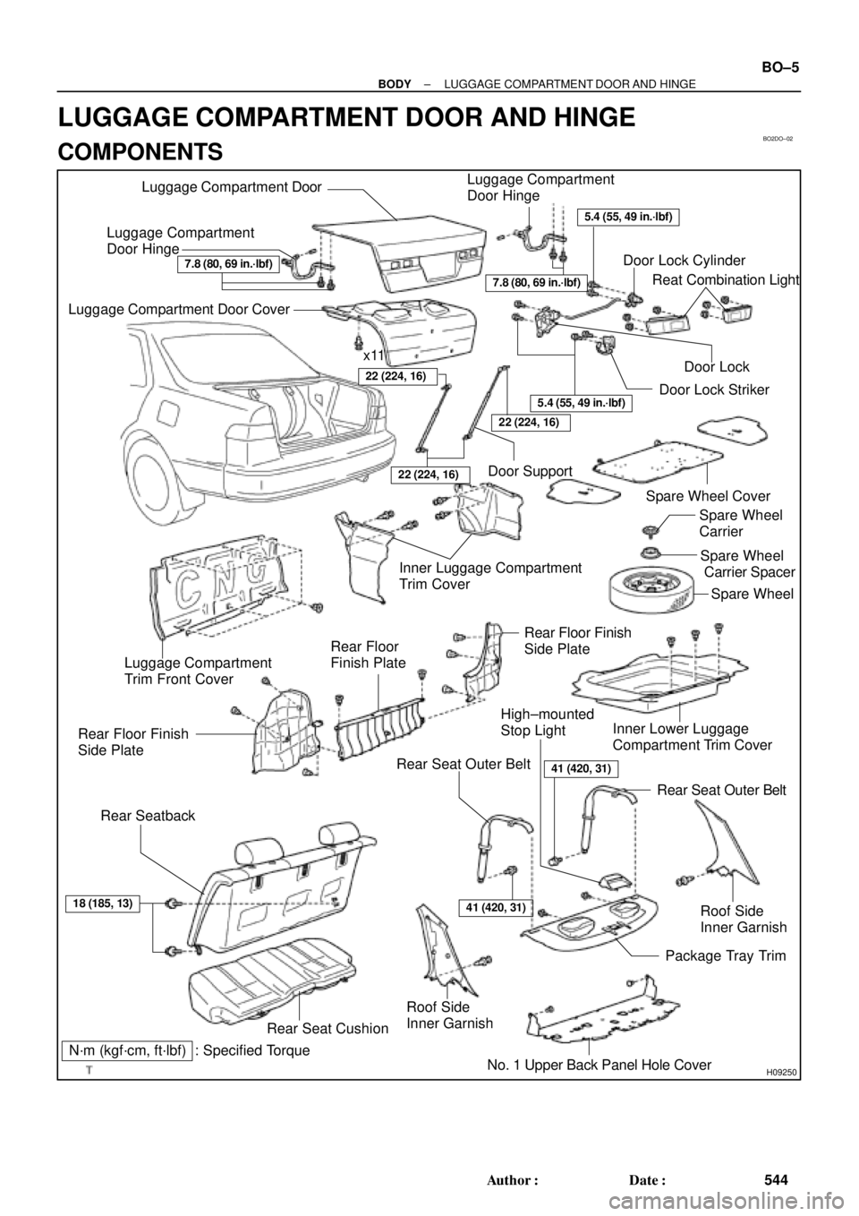
BO2DO±02
H09250
Luggage Compartment
Door HingeLuggage Compartment DoorLuggage Compartment
Door Hinge
Door Lock Cylinder
Door Lock StrikerDoor Lock
Door Support
Inner Luggage Compartment
Trim Cover
Spare Wheel
Rear SeatbackSpare Wheel Cover
Spare Wheel
Carrier
Spare Wheel
Carrier Spacer
Luggage Compartment
Trim Front Cover
Rear Floor Finish
Side Plate
Rear Seat Outer BeltInner Lower Luggage
Compartment Trim Cover
Rear Seat Outer Belt Rear Floor Finish
Side Plate
Rear Seat CushionRoof Side
Inner Garnish
No. 1 Upper Back Panel Hole CoverPackage Tray Trim High±mounted
Stop Light
Roof Side
Inner Garnish
41 (420, 31)
41 (420, 31)
7.8 (80, 69 in.´lbf)
5.4 (55, 49 in.´lbf)
Luggage Compartment Door Cover
x11
N´m (kgf´cm, ft´lbf) : Specified TorqueReat Combination Light
22 (224, 16)
22 (224, 16)
5.4 (55, 49 in.´lbf)
18 (185, 13)
7.8 (80, 69 in.´lbf)
22 (224, 16)
Rear Floor
Finish Plate
± BODYLUGGAGE COMPARTMENT DOOR AND HINGE
BO±5
544 Author�: Date�:
LUGGAGE COMPARTMENT DOOR AND HINGE
COMPONENTS
Page 992 of 4592
BO2DP±01
H09251
H09252
BO±6
± BODYLUGGAGE COMPARTMENT DOOR AND HINGE
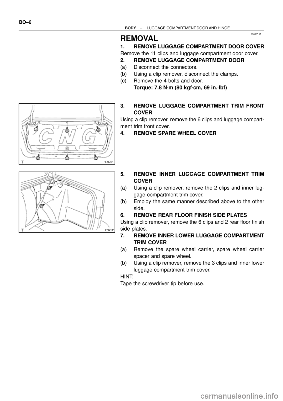
REMOVAL
1. REMOVE LUGGAGE COMPARTMENT DOOR COVER
Remove the 11 clips and luggage compartment door cover.
2. REMOVE LUGGAGE COMPARTMENT DOOR
(a) Disconnect the connectors.
(b) Using a clip remover, disconnect the clamps.
(c) Remove the 4 bolts and door.
Torque: 7.8 N´m (80 kgf´cm, 69 in.´lbf)
3. REMOVE LUGGAGE COMPARTMENT TRIM FRONT
COVER
Using a clip remover, remove the 6 clips and luggage compart-
ment trim front cover.
4. REMOVE SPARE WHEEL COVER
5. REMOVE INNER LUGGAGE COMPARTMENT TRIM
COVER
(a) Using a clip remover, remove the 2 clips and inner lug-
gage compartment trim cover.
(b) Employ the same manner described above to the other
side.
6. REMOVE REAR FLOOR FINISH SIDE PLATES
Using a clip remover, remove the 6 clips and 2 rear floor finish
side plates.
7. REMOVE INNER LOWER LUGGAGE COMPARTMENT
TRIM COVER
(a) Remove the spare wheel carrier, spare wheel carrier
spacer and spare wheel.
(b) Using a clip remover, remove the 3 clips and inner lower
luggage compartment trim cover.
HINT:
Tape the screwdriver tip before use.
Page 1018 of 4592
F05595
F05596
BR0AB±03
F05597
R00252
BR±4
± BRAKEBRAKE FLUID
2027 Author�: Date�:
BRAKE FLUID
BLEEDING
HINT:
If any work is done on the brake system or if air is suspected in
the brake lines, bleed the air from the system.
NOTICE:
Do not let brake fluid remain on a painted surface. Wash it
off immediately.
1. FILL BRAKE RESERVOIR WITH BRAKE FLUID
Check the fluid level in the reservoir after bleeding each wheel.
Add fluid, if necessary.
Fluid: SAEJ1703 or FMVSS No.116 DOT 3
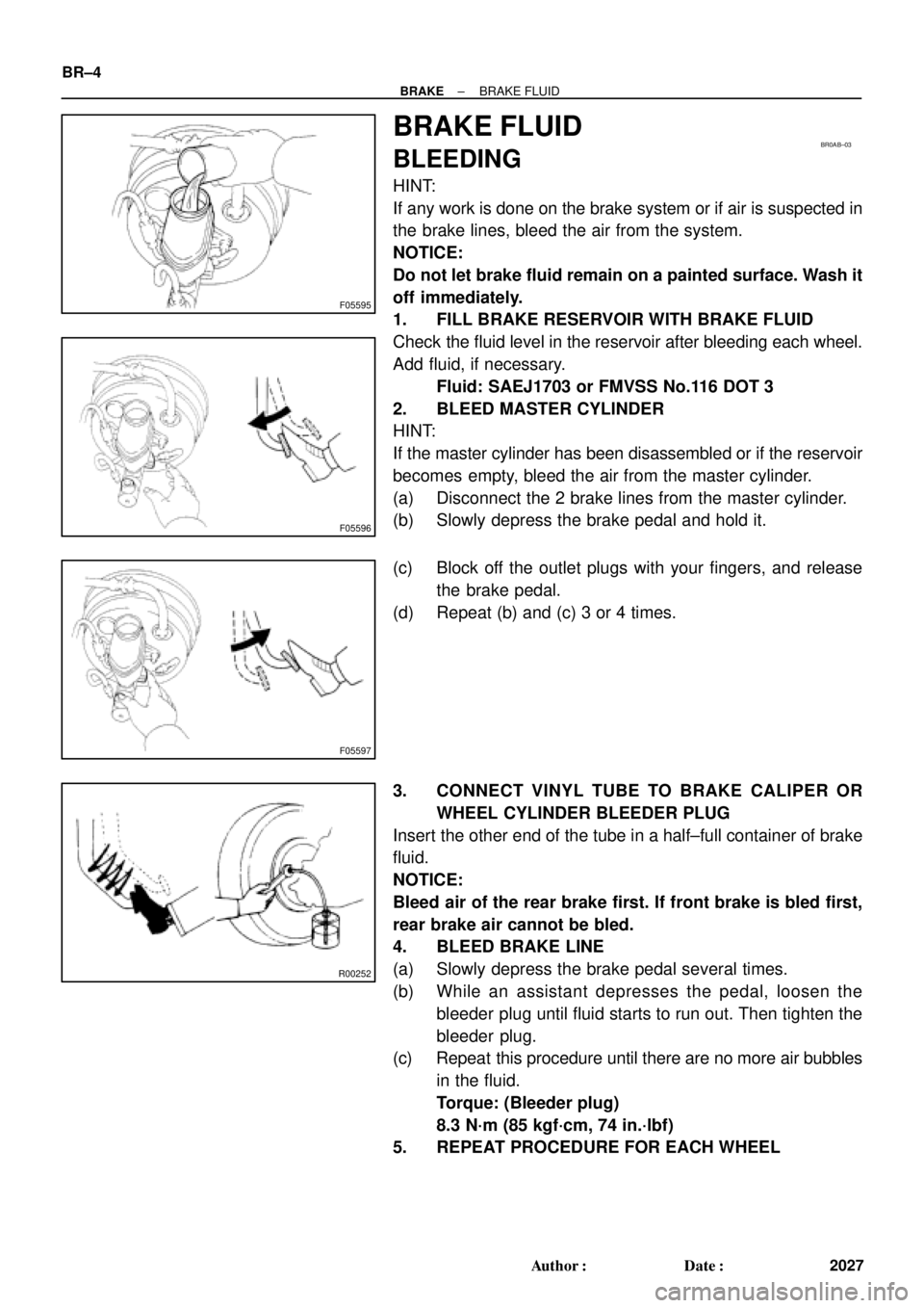
2. BLEED MASTER CYLINDER
HINT:
If the master cylinder has been disassembled or if the reservoir
becomes empty, bleed the air from the master cylinder.
(a) Disconnect the 2 brake lines from the master cylinder.
(b) Slowly depress the brake pedal and hold it.
(c) Block off the outlet plugs with your fingers, and release
the brake pedal.
(d) Repeat (b) and (c) 3 or 4 times.
3. CONNECT VINYL TUBE TO BRAKE CALIPER OR
WHEEL CYLINDER BLEEDER PLUG
Insert the other end of the tube in a half±full container of brake
fluid.
NOTICE:
Bleed air of the rear brake first. If front brake is bled first,
rear brake air cannot be bled.
4. BLEED BRAKE LINE
(a) Slowly depress the brake pedal several times.
(b) While an assistant depresses the pedal, loosen the
bleeder plug until fluid starts to run out. Then tighten the
bleeder plug.
(c) Repeat this procedure until there are no more air bubbles
in the fluid.
Torque: (Bleeder plug)
8.3 N´m (85 kgf´cm, 74 in.´lbf)
5. REPEAT PROCEDURE FOR EACH WHEEL
Page 1036 of 4592
BR0AP±03
F07213
R02874
BR±22
± BRAKEFRONT BRAKE PAD
2045 Author�: Date�:
REPLACEMENT
1. REMOVE FRONT WHEEL
Remove the wheel and temporarily fasten the disc with hub
nuts.
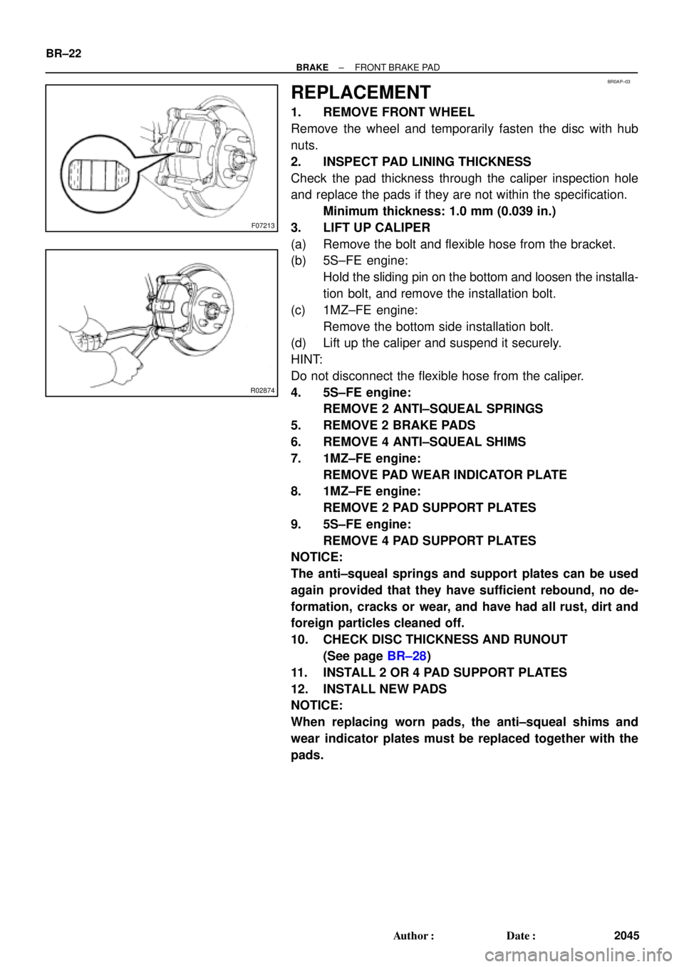
2. INSPECT PAD LINING THICKNESS
Check the pad thickness through the caliper inspection hole
and replace the pads if they are not within the specification.
Minimum thickness: 1.0 mm (0.039 in.)
3. LIFT UP CALIPER
(a) Remove the bolt and flexible hose from the bracket.
(b) 5S±FE engine:
Hold the sliding pin on the bottom and loosen the installa-
tion bolt, and remove the installation bolt.
(c) 1MZ±FE engine:
Remove the bottom side installation bolt.
(d) Lift up the caliper and suspend it securely.
HINT:
Do not disconnect the flexible hose from the caliper.
4. 5S±FE engine:
REMOVE 2 ANTI±SQUEAL SPRINGS
5. REMOVE 2 BRAKE PADS
6. REMOVE 4 ANTI±SQUEAL SHIMS
7. 1MZ±FE engine:
REMOVE PAD WEAR INDICATOR PLATE
8. 1MZ±FE engine:
REMOVE 2 PAD SUPPORT PLATES
9. 5S±FE engine:
REMOVE 4 PAD SUPPORT PLATES
NOTICE:
The anti±squeal springs and support plates can be used
again provided that they have sufficient rebound, no de-
formation, cracks or wear, and have had all rust, dirt and
foreign particles cleaned off.
10. CHECK DISC THICKNESS AND RUNOUT
(See page BR±28)
11. INSTALL 2 OR 4 PAD SUPPORT PLATES
12. INSTALL NEW PADS
NOTICE:
When replacing worn pads, the anti±squeal shims and
wear indicator plates must be replaced together with the
pads.