Page 1242 of 4592
A00309
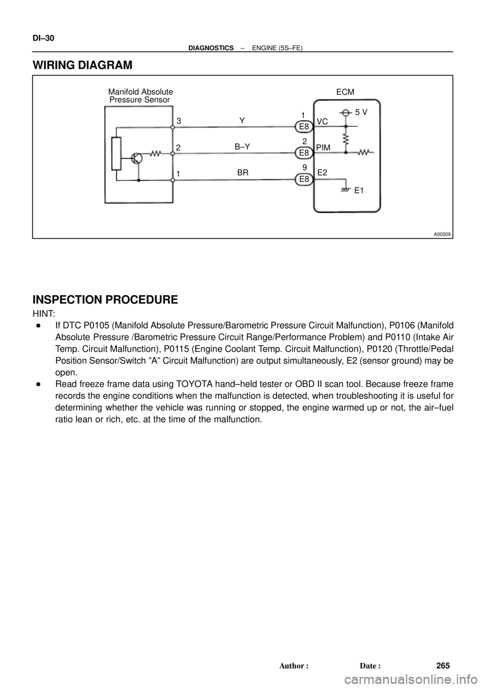
ECM Manifold Absolute
Pressure Sensor
1PIMVC
E2 Y
B±Y
BRE8
E8
E8 3
25 V
E1 1
2
9 DI±30
± DIAGNOSTICSENGINE (5S±FE)
265 Author�: Date�:
WIRING DIAGRAM
INSPECTION PROCEDURE
HINT:
�If DTC P0105 (Manifold Absolute Pressure/Barometric Pressure Circuit Malfunction), P0106 (Manifold
Absolute Pressure /Barometric Pressure Circuit Range/Performance Problem) and P0110 (Intake Air
Temp. Circuit Malfunction), P0115 (Engine Coolant Temp. Circuit Malfunction), P0120 (Throttle/Pedal
Position Sensor/Switch ºAº Circuit Malfunction) are output simultaneously, E2 (sensor ground) may be
open.
�Read freeze frame data using TOYOTA hand±held tester or OBD II scan tool. Because freeze frame
records the engine conditions when the malfunction is detected, when troubleshooting it is useful for
determining whether the vehicle was running or stopped, the engine warmed up or not, the air±fuel
ratio lean or rich, etc. at the time of the malfunction.
Page 1245 of 4592

DI±33
268 Author�: Date�:
DTC P0106 Manifold Absolute Pressure Circuit
Range/Performance Problem
CIRCUIT DESCRIPTION
Refer to DTC P0105 (Manifold Absolute Pressure/Barom")
± DIAGNOSTICSENGINE (5S±FE)
DI±33
268 Author�: Date�:
DTC P0106 Manifold Absolute Pressure Circuit
Range/Performance Problem
CIRCUIT DESCRIPTION
Refer to DTC P0105 (Manifold Absolute Pressure/Barometric Pressure Circuit Malfunction) on page
DI±29.
DTC No.DTC Detecting ConditionTrouble Area
P0106
After engine is warmed up, conditions (a) and (b) continue with
engine speed 400 ~ 1,000 rpm
(2 trip detection logic)
(a) Throttle valve fully closed
(b) Manifold absolute pressure sensor output > 3.0 V
�Manifold absolute pressure sensorP0106Condition (c) and (d) continue with engine speed 2,500 rpm or
less
(2 trip detection logic)
(c) VTA > 1.85
(d) Manifold absolute pressure sensor output < 1.0 V
�Manifold absolute ressure sensor
�Vacuum line
WIRING DIAGRAM
Refer to DTC P0105 (Manifold Absolute Pressure/Barometric Pressure Circuit Malfunction) on page
DI±29.
INSPECTION PROCEDURE
HINT:
�If DTC P0105 (Manifold Absolute Pressure/Barometric Pressure Circuit Malfunction) and P0106 (Man-
ifold Absolute Pressure /Barometric Pressure Circuit Range/Performance Problem) are output simul-
taneously, manifold absolute pressure sensor circuit may be open. Perform troubleshooting of DTC
P0105 first.
�If DTC P0105 (Manifold Absolute Pressure/Barometric Pressure Circuit Malfunction), P0106 (Manifold
Absolute Pressure /Barometric Pressure Circuit Range/Performance Problem), P0110 (Intake Air
Temp. Circuit Malfunction), P0115 (Engine Coolant Temp. Circuit Malfunction) and P0120 (Throttle/
Pedal Position Sensor/Switch ºAº Circuit Malfunction) are output simultaneously, E2 (sensor ground)
may be open.
�Read freeze frame data using TOYOTA hand±held tester or OBD II scan tool. Because freeze frame
records the engine conditions when the malfunction is detected, when troubleshooting it is useful for
determining whether the vehicle was running or stopped, the engine warmed up or not, the air±fuel
ratio lean or rich, etc. at the time of the malfunction.
1 Are there any other codes (besides DTC P0106) being output?
YES Go to relevant DTC chart.
NO
DI00N±04
Page 1248 of 4592
A00310
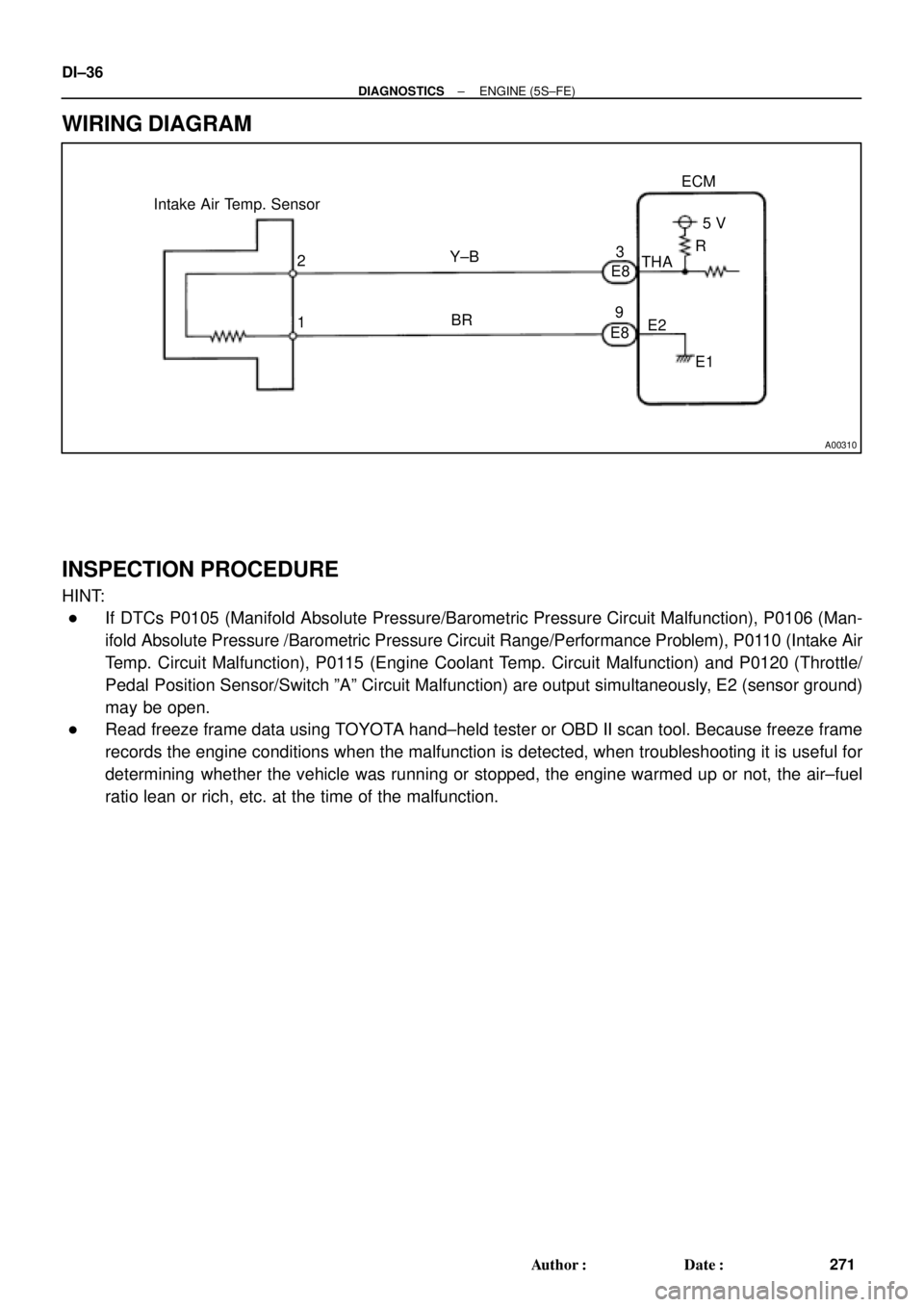
Intake Air Temp. Sensor
E8
E83
9ECM
5 V
THA
E2
E1 R
Y±B
BR 2
1 DI±36
± DIAGNOSTICSENGINE (5S±FE)
271 Author�: Date�:
WIRING DIAGRAM
INSPECTION PROCEDURE
HINT:
�If DTCs P0105 (Manifold Absolute Pressure/Barometric Pressure Circuit Malfunction), P0106 (Man-
ifold Absolute Pressure /Barometric Pressure Circuit Range/Performance Problem), P0110 (Intake Air
Temp. Circuit Malfunction), P0115 (Engine Coolant Temp. Circuit Malfunction) and P0120 (Throttle/
Pedal Position Sensor/Switch ºAº Circuit Malfunction) are output simultaneously, E2 (sensor ground)
may be open.
�Read freeze frame data using TOYOTA hand±held tester or OBD II scan tool. Because freeze frame
records the engine conditions when the malfunction is detected, when troubleshooting it is useful for
determining whether the vehicle was running or stopped, the engine warmed up or not, the air±fuel
ratio lean or rich, etc. at the time of the malfunction.
Page 1254 of 4592
A00310
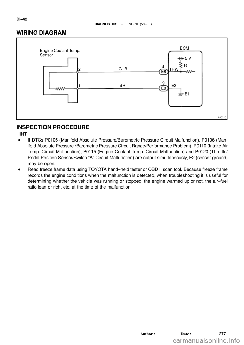
Engine Coolant Temp.
Sensor
2
1ECM
G±B
BR4
E8
E895 V
THW
E2
E1 R DI±42
± DIAGNOSTICSENGINE (5S±FE)
277 Author�: Date�:
WIRING DIAGRAM
INSPECTION PROCEDURE
HINT:
�If DTCs P0105 (Manifold Absolute Pressure/Barometric Pressure Circuit Malfunction), P0106 (Man-
ifold Absolute Pressure /Barometric Pressure Circuit Range/Performance Problem), P0110 (Intake Air
Temp. Circuit Malfunction), P0115 (Engine Coolant Temp. Circuit Malfunction) and P0120 (Throttle/
Pedal Position Sensor/Switch ºAº Circuit Malfunction) are output simultaneously, E2 (sensor ground)
may be open.
�Read freeze frame data using TOYOTA hand±held tester or OBD II scan tool. Because freeze frame
records the engine conditions when the malfunction is detected, when troubleshooting it is useful for
determining whether the vehicle was running or stopped, the engine warmed up or not, the air±fuel
ratio lean or rich, etc. at the time of the malfunction.
Page 1262 of 4592

E8 E810
(*1)
DI±50
± DIAGNOSTICSENGINE (5S±FE)
285 Author�: Date�:
WIRING DIAGRAM")
A03595
Throttle Position Sensor
ECM
E8
E8 1
3
2Y
LG
BR1
11
9VC
VTA
E25 V
*1: w/o Immobiliser
*2: w/ Immobiliser(*2)
E8 E810
(*1)
DI±50
± DIAGNOSTICSENGINE (5S±FE)
285 Author�: Date�:
WIRING DIAGRAM
INSPECTION PROCEDURE
HINT:
�If DTCs P0105 (Manifold Absolute Pressure/Barometric Pressure Circuit Malfunction), P0106 (Man-
ifold Absolute Pressure /Barometric Pressure Circuit Range/Performance Problem), P0110 (Intake Air
Temp. Circuit Malfunction), P0115 (Engine Coolant Temp. Circuit Malfunction) and P0120 (Throttle/
Pedal Position Sensor/Switch ºAº Circuit Malfunction) are output simultaneously, E2 (sensor ground)
may be open.
�Read freeze frame data using TOYOTA hand±held tester or OBD II scan tool. Because freeze frame
records the engine conditions when the malfunction is detected, when troubleshooting it is useful for
determining whether the vehicle was running or stopped, the engine warmed up or not, the air±fuel
ratio lean or rich, etc. at the time of the malfunction.
Page 1270 of 4592
DI±58
± DIAGNOSTICSENGINE (5S±FE)
293 Author�: Date�:
3 Check for open and short in harness and connector between ECM and A/F sen-
sor (See page IN±31).
NG Repair or replace harness or connector.
OK
4 Check resistance of A/F sensor heater (See page SF±59).
NG Replace A/F sensor.
OK
5 Check air induction system (See page SF±1).
NG Replace or replace.
OK
6 Check EGR system (See page EC±12).
NG Repair EGR system.
OK
7 Check fuel pressure (See page SF±6).
NG Check and repair fuel pump, fuel pipe line and
filter (See page SF±1).
OK
Page 1276 of 4592
DI±64
± DIAGNOSTICSENGINE (5S±FE)
299 Author�: Date�:
4 Check whether misfire is occurred or not by monitoring DTC and data list.
NG Perform troubleshooting for misfire
(See page DI±163).
OK
5 Check air induction system (See page SF±1).
NG Repair or replace.
OK
6 Check EGR system (See page EC±12).
NG Repair EGR system.
OK
7 Check fuel pressure (See page SF±6).
NG Check and repair fuel pump, fuel pipe line and
filter (See page SF±1).
OK
8 Check injector injection (See page SF±23)
NG Replace injector.
OK
Page 1281 of 4592
± DIAGNOSTICSENGINE (5S±FE)
DI±69
304 Author�: Date�:
4 Check air induction system (See page SF±1).
NG Repair or replace.
OK
5 Check EGR system (See page EC±12).
NG Repair EGR system.
OK
6 Check fuel pressure (See page SF±6).
NG Check and repair fuel pump, fuel pipe line and
filter (See page SF±1).
OK
7 Check injector injection (See page SF±23).
NG Replace injector.
OK
Replace oxygen sensor
(bank 1 sensor 1).