Page 1364 of 4592

DI±152
± DIAGNOSTICSENGINE (5S±FE)
387 Author�: Date�:
DTC P1130 A/F Sensor Circuit Range/Performance
Malfunction (Only for California Spec.)
CIRCUIT DESCRIPTION
Refer to DTC P0125 (Insufficient Coolant Temp. for Closed Loop Fuel Control (Only for California Spec.))
on page DI±61.
DTC No.DTC Detecting ConditionTrouble Area
Voltage output* of A/F sensor remains at 3.8 V or more, or 2.8
V or less, during engine running after engine is warmed up (2
trip detection logic)
*: Output value changes at the inside of ECM only
P1130Voltage output* of A/F sensor does not change from 3.30 V,
during engine running after engine is warmed up
(2 trip detection logic)
*: Output value changes at inside of ECM only�Open or short in A/F sensor circuit
�A/F sensor
�ECM
Open or short in A/F sensor circuit
(2 trip detection logic)
HINT:
�After confirming DTC P1130, use the OBD II scan tool or TOYOTA hand-held tester to confirm voltage
output of A/F sensor (AFS B1 S1 / O2S B1 S1) from the CURRENT DATA.
�The A/F sensor's output voltage and the short-term fuel trim value can be read using the OBD II scan
tool or TOYOTA hand-held tester.
�The ECM controls the voltage of AF� and AF� terminals of ECM to the fixed voltage. Therefore, it
is impossible to confirm the A/F sensor output voltage without OBD II scan tool or TOYOTA hand±held
tester.
�OBD II scan tool (excluding TOYOTA hand-held tester) displays the one fifth of the A/F sensor output
voltage which is displayed on the TOYOTA hand-held tester.
WIRING DIAGRAM
Refer to DTC P0125 (Insufficient Coolant Temp. for Closed Loop Fuel Control (Only for California Spec.))
on page DI±61.
DI01D±06
Page 1373 of 4592
A00430
HTAF (+) ON
± DIAGNOSTICSENGINE (5S±FE)
DI±161
396 Author�: Date�:
DTC P1135 A/F Sensor Heater Circuit Malfunction
(Only for California Spec.)
CIRCUIT DESCRIPTION
Refer to DTC P0125 (Insufficient Coolant Temp. for Closed Loop Fuel Control (Only for California Spec.))
on page DI±61.
DTC No.DTC Detecting ConditionTrouble Area
P1135
When heater operates, heater current exceeds 8 A
(2 trip detection logic)�Open or short in heater circuit of A/F sensor
A/F h tP1135Heater current of 0.25 A or less when heater operates
(2 trip detection logic)�A/F sensor heater
�ECM
WIRING DIAGRAM
Refer to DTC P0125 (Insufficient Coolant Temp. for Closed Loop Fuel Control (Only for California Spec.))
on page DI±61.
INSPECTION PROCEDURE
HINT:
Read freeze frame data using TOYOTA hand±held tester or OBD II scan tool. Because freeze frame records
the engine conditions when the malfunction is detected, when troubleshooting it is useful for determining
whether the vehicle was running or stopped, the engine warmed up or not, the air±fuel ratio lean or rich, etc.
at the time of the malfunction.
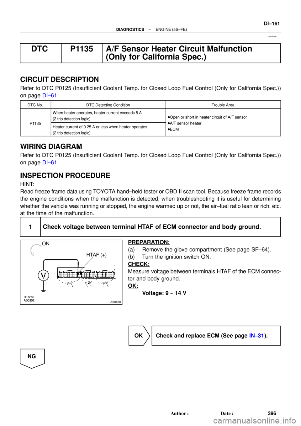
1 Check voltage between terminal HTAF of ECM connector and body ground.
PREPARATION:
(a) Remove the glove compartment (See page SF±64).
(b) Turn the ignition switch ON.
CHECK:
Measure voltage between terminals HTAF of the ECM connec-
tor and body ground.
OK:
Voltage: 9 ~ 14 V
OK Check and replace ECM (See page IN±31).
NG
DI01F±05
Page 1376 of 4592
A07122
IG Switch
B±R
BatteryEngine Room
J/B No.2
76B±R13
1II3B±R
B
BR
Spark Plug
Spark Plug
2
3 2
3 4
Tr2 Igniter
No.1
Ignition
Coil
No.1
FL Block
Y±R
BR
B
20
19
IGT2
Tr1
E9
E9
E9
W±R
IGT1
IGF5 V
Tr1
Ignition Coil
No.2
Igniter
No.2
AA A
EC
Tr2
W±R
B±R 5 51B 1K
Instrument
W±R
W±R
2L 2A
4 1
AM2B
F4 F6 1
1
B±G
MAIN FL
3 1
4
J/C J25
*1: w/o Immobiliser
*2: w/ Immobiliser(*1) (*2)
ECM
E9 23
E9 22
E9 17
(*1) (*2)
W±R
Panel J/BB
B
BR
BR J19
J/C
DI±164
± DIAGNOSTICSENGINE (5S±FE)
399 Author�: Date�:
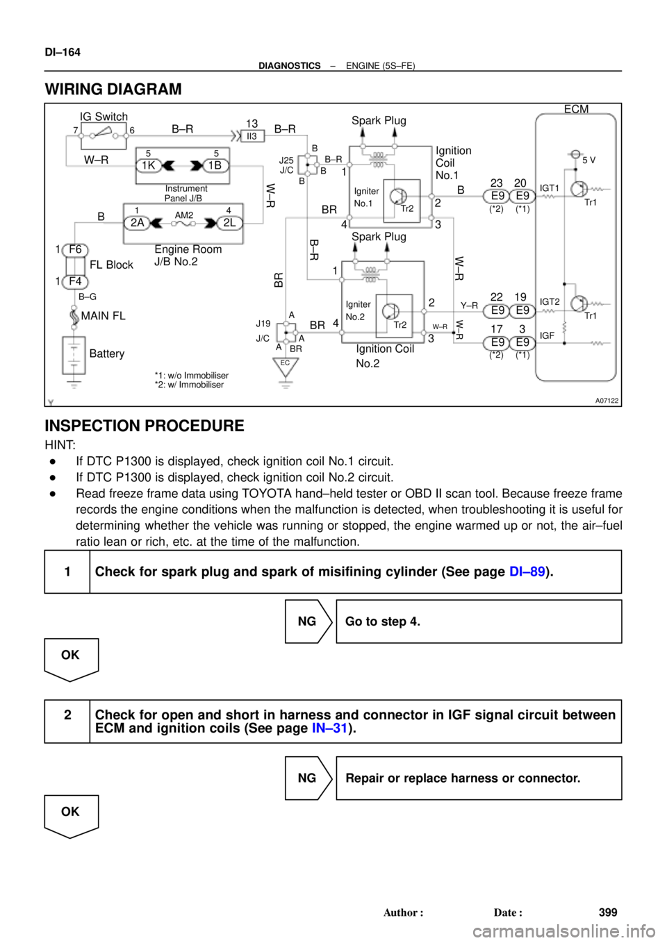
WIRING DIAGRAM
INSPECTION PROCEDURE
HINT:
�If DTC P1300 is displayed, check ignition coil No.1 circuit.
�If DTC P1300 is displayed, check ignition coil No.2 circuit.
�Read freeze frame data using TOYOTA hand±held tester or OBD II scan tool. Because freeze frame
records the engine conditions when the malfunction is detected, when troubleshooting it is useful for
determining whether the vehicle was running or stopped, the engine warmed up or not, the air±fuel
ratio lean or rich, etc. at the time of the malfunction.
1 Check for spark plug and spark of misifining cylinder (See page DI±89).
NG Go to step 4.
OK
2 Check for open and short in harness and connector in IGF signal circuit between
ECM and ignition coils (See page IN±31).
NG Repair or replace harness or connector.
OK
Page 1381 of 4592
± DIAGNOSTICSENGINE (5S±FE)
DI±169
404 Author�: Date�:
DTC P1335 Crankshaft Position Sensor Circuit
Malfunction (During engine running)
CIRCUIT DESCRIPTION
Refer to DTC P0335 (Crankshaft Position ºAº Circuit Malfunction) on page DI±100.
DTC No.DTC Detecting ConditionTrouble Area
P1335
If conditions (a) through (c) are met:
(a) NE � 1,000 rpm
(b) NE signal is not detected for over 50 m sec.
(c) Not during cranking�Open or short in crankshaft position sensor circuit
�Crankshaft position sensor
�ECM
WIRING DIAGRAM
Refer to DTC P0335 (Crankshaft Position ºAº Circuit Malfunction) on page DI±100.
INSPECTION PROCEDURE
Refer to DTC P0335 (Crankshaft Position ºAº Circuit Malfunction) on page DI±100.
DI1K1±02
Page 1382 of 4592
A03604
ECM
STP 4
E7
G±W G±WJ27 J28 1R 1R
1SJ27
J/C
AC Instrument Panel J/B
5
2 4
7
12
G±WLight
Failure
Sensor
Stop
Light
(LH) Stop
Light
(RH) G±R
2
52
5
W±B
W±B
BP High
Mount
Stop
Light
2
1R
A
A
J40
J/C
BL
1
W±B
Stop Light
Switch
2
BatteryW±B W
1C 7
STOP
41BInstrument
Panel J/B
B±R
B±R
F9 2 F9 1
ALT
F4MAIN
FL
FL Block
G±W
1
*1: w/o Immobiliser
*2: w/ Immobiliser(*1) (*2)
E79 DI±170
± DIAGNOSTICSENGINE (5S±FE)
405 Author�: Date�:
DTC P1520 Stop Light Switch Signal Malfunction (Only
for A/T)
CIRCUIT DESCRIPTION
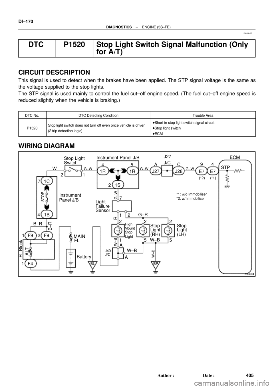
This signal is used to detect when the brakes have been applied. The STP signal voltage is the same as
the voltage supplied to the stop lights.
The STP signal is used mainly to control the fuel cut±off engine speed. (The fuel cut±off engine speed is
reduced slightly when the vehicle is braking.)
DTC No.DTC Detecting ConditionTrouble Area
P1520Stop light switch does not turn off even once vehicle is driven
(2 trip detection logic)�Short in stop light switch signal circuit
�Stop light switch
�ECM
WIRING DIAGRAM
DI01H±07
Page 1385 of 4592
A03605
Engine Room J/B No.2
EFI11
B
Battery B±G11
2A E7ECM
F4BATT
2JB±Y
F68
FL Block
MAIN FL
*1: w/o Immobiliser
*2: w/ Immobiliser(*1)
(*2)
E72
± DIAGNOSTICSENGINE (5S±FE)
DI±173
408 Author�: Date�:
DTC P1600 ECM BATT Malfunction
CIRCUIT DESCRIPTION
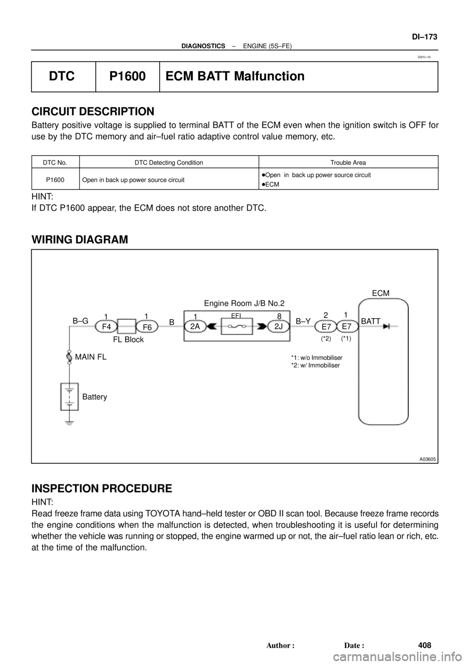
Battery positive voltage is supplied to terminal BATT of the ECM even when the ignition switch is OFF for
use by the DTC memory and air±fuel ratio adaptive control value memory, etc.
DTC No.DTC Detecting ConditionTrouble Area
P1600Open in back up power source circuit�Open in back up power source circuit
�ECM
HINT:
If DTC P1600 appear, the ECM does not store another DTC.
WIRING DIAGRAM
INSPECTION PROCEDURE
HINT:
Read freeze frame data using TOYOTA hand±held tester or OBD II scan tool. Because freeze frame records
the engine conditions when the malfunction is detected, when troubleshooting it is useful for determining
whether the vehicle was running or stopped, the engine warmed up or not, the air±fuel ratio lean or rich, etc.
at the time of the malfunction.
DI01I±10
Page 1387 of 4592

± DIAGNOSTICSENGINE (5S±FE)
DI±175
410 Author�: Date�:
DTC P1780 Park/Neutral Position Switch Malfunction
(Only for A/T)
CIRCUIT DESCRIPTION
The park/neutral position switch goes on when the shift lever is in the N or P shift position. When it goes on
terminal NSW of the ECM is grounded to body ground via the starter relay thus the terminal NSW voltage
becomes 0V. When the shift lever is in the D, 2, L or R position, the park/neutral position switch goes off,
so the voltage of ECM. Terminal NSW becomes battery positive voltage, the voltage of the ECM internal
power source.
If the shift lever is moved from the N position to the D position, this signal is used for air±fuel ratio correction
and for idle speed control (estimated control), etc.
DTC No.DTC Detecting ConditionTrouble Area
2 or more switches are ON simultaneously for P, R, N, D, 2
and L positions
(2 trip detection logic)
Sh t i k/ t l iti it h i it
P1780When driving under conditions (a) and (b) for 30 sec. or more
park/neutral position switch is ON (N position):
(2 trip detection logic)
(a) Vehicle speed: 80 km/h (50 mph) or more
(b) Engine speed: 2,000 ~ 5,000 rpm�Short in park/neutral position switch circuit
�Park/neutral position switch
�ECM
HINT:
After confirming DTC P1780, use the TOYOTA hand±held tester to confirm the PNP switch signal from the
CURRENT DATA.
WIRING DIAGRAM
Refer to DTC P1780 on page DI±424.
INSPECTION PROCEDURE
HINT:
Read freeze frame data using TOYOTA hand±held tester or OBD II scan tool. Because freeze frame records
the engine conditions when the malfunction is detected, when troubleshooting it is useful for determining
whether the vehicle was running or stopped, the engine warmed up or not, the air±fuel ratio lean or rich, etc.
at the time of the malfunction.
Refer to DTC P1780 on DI±424.
DI01J±05
Page 1388 of 4592
A03606
ECM
STA 11
E1 E7 Instrument
Panel J/BPark/Neutral
Position Switch
Clutch Start
SwitchB
J7
J7
B J8CJ/C II2 10 11
II26
2
B±O
5
1 B±W (M/T)
GR B±W (A/T)
B±WB±O (A/T,*2)
GR (A/T,*1) B±W
J/C J29
B B
B 3
1J 4
1K
5
1B 1K5
STARTER
R
8
7
W±R
IG SwitchW±R
Engine Room
J/B No. 2B
B FL
Block
B±G
B±R
BatteryStarter 11
W±B
A
J11
J/C
IG
42L
1
2A
3
2B
AM2
MAINST
Relay11 2 J
92K 52D 1 1
F6 F41 5
2 3
B±O (*2)
S2B±R MAIN
FL
GR (*1)(A/T)
S1
*1: TMC Made
*2: TMMK Made
GR (*1)
(*2)
(M/T)
B±O (*2) GR (*1)
DI±176
± DIAGNOSTICSENGINE (5S±FE)
411 Author�: Date�:
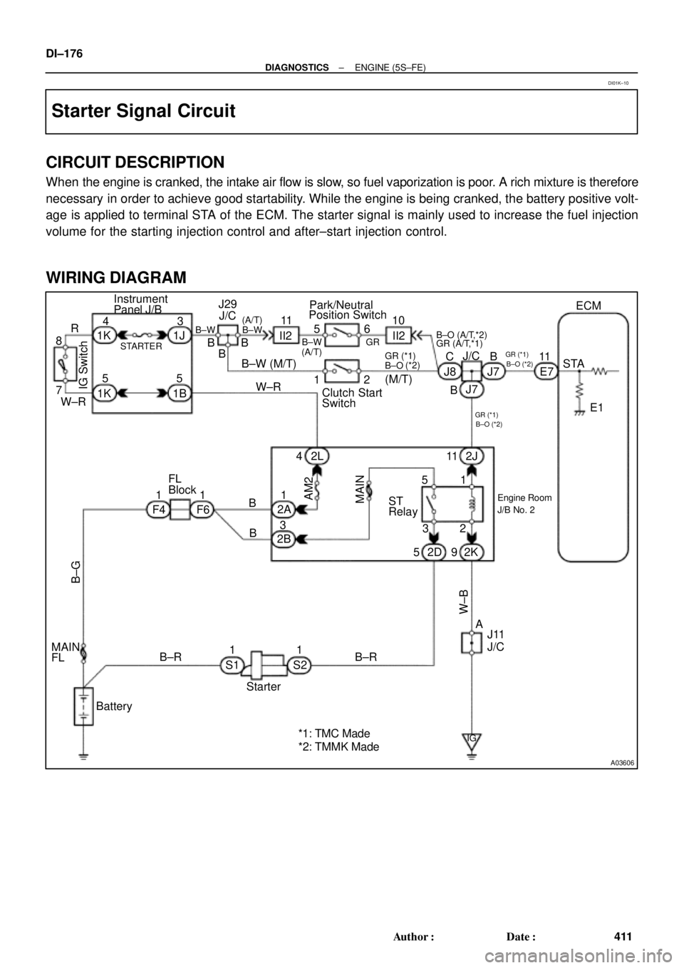
Starter Signal Circuit
CIRCUIT DESCRIPTION
When the engine is cranked, the intake air flow is slow, so fuel vaporization is poor. A rich mixture is therefore
necessary in order to achieve good startability. While the engine is being cranked, the battery positive volt-
age is applied to terminal STA of the ECM. The starter signal is mainly used to increase the fuel injection
volume for the starting injection control and after±start injection control.
WIRING DIAGRAM
DI01K±10