Page 1268 of 4592

A03597
B±Y
FL
Block47
EFI
IGN
14 2
4 EFI
Relay
21
53
B±Y
BR
3
12 B
B
1
24 3 9
II3
J/CB
W±R
P±B
W
BG
P±B 56
2
5
1K
14
HT2 21 O 1W
E9E8
E9 E8
MAIN FLE8 1B
B 1ECMAF�
OX2 HTAF
AF� 1K
2F
E03 E1E04 A/F
Sensor
Engine Room R/B No.2
B±YJ19 J/C
2
1
II2II3
II3
EB
Heated
Oxygen
Sensor
(Bank 1
Sensor 2)
EC
Instrument
Panel J/B7
3 5
6
7
2L 2A
F611
F4
B±G
Battery B±R
2K
2J
W±B
3.3V
3.0V
AM2 B
W±R
J27
*1: w/o Immobiliser
*2: w/ Immobiliser
(*1)
(*2)
to Analog±Digital
Converter
E914 E8 13
(*1) (*2) J27
B±Y
B±Y
IG Switch
B±R
*3: California
(*6) (*3) (*6) (*3)
(*1)
2
MREL
E107
(*2)
EE
J27 J27
J/C
B BB±Y
II4
6
B±W(*2)
B±W(*2)
*5:TMC Made
*6:TMMK Made
L(*5)
(*3)
B±W(*5)
(*3)
BR
*4: Except California
DI±56
± DIAGNOSTICSENGINE (5S±FE)
291 Author�: Date�:
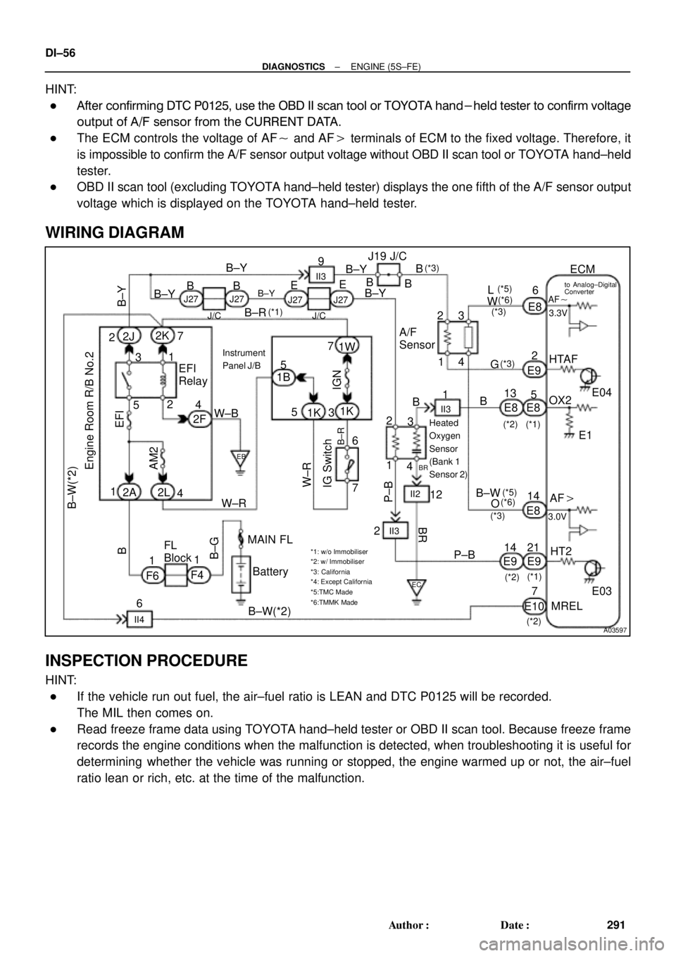
HINT:
�After confirming DTC P0125, use the OBD II scan tool or TOYOTA hand-held tester to confirm voltage
output of A/F sensor from the CURRENT DATA.
�The ECM controls the voltage of AF� and AF� terminals of ECM to the fixed voltage. Therefore, it
is impossible to confirm the A/F sensor output voltage without OBD II scan tool or TOYOTA hand±held
tester.
�OBD II scan tool (excluding TOYOTA hand±held tester) displays the one fifth of the A/F sensor output
voltage which is displayed on the TOYOTA hand±held tester.
WIRING DIAGRAM
INSPECTION PROCEDURE
HINT:
�If the vehicle run out fuel, the air±fuel ratio is LEAN and DTC P0125 will be recorded.
The MIL then comes on.
�Read freeze frame data using TOYOTA hand±held tester or OBD II scan tool. Because freeze frame
records the engine conditions when the malfunction is detected, when troubleshooting it is useful for
determining whether the vehicle was running or stopped, the engine warmed up or not, the air±fuel
ratio lean or rich, etc. at the time of the malfunction.
Page 1274 of 4592

A03596
B±Y
Engine Room R/B No.2
Battery
IG Switch17
EFI
W±R7 7 2
5 EFI
Relay
5 3
24
W±BP±B
BR14 2314 2
3
9
II3
B±Y
B±Y
W±R B
W B±Y
B
BR6
128
25 1 2K
21 1KE8
E9
AM2
E8
E9ECM
OX1
OX2 HT1
HT2 1K 2JB±Y
J/C
1B
2F5 B±R
1W
Heated
Oxygen
Sensor
(Bank 1
Sensor 1)
II2
II3Heated
Oxygen
Sensor
(Bank 1
Sensor 2)E03
B J19 J/C
BBB
3
MAIN 2A 2L 4
F4 F6FL
Block
B±GP±B
J27 J27
1
EB
EC
6
IGN
E03 L±YE1
E1 Instrument
Panel J/B
11
B±R
*1: w/o Immobiliser
*2: w/ Immobiliser
(*2) (*1)
E9 14E8 E9 E85
1
13
(*2) (*1)(*1) (*2)(*1) (*2) (*3)
EB±Y
(*3) (*3)
(*1)FL
*3: Except California BII3
E
B±YJ27 J27
MREL
E10 B±W
II4
6
B±W(*2)
(*3)
7(*2)(*2)
BR BR
DI±62
± DIAGNOSTICSENGINE (5S±FE)
297 Author�: Date�:
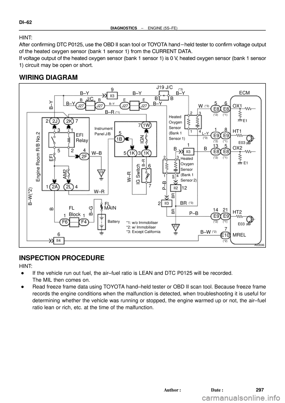
HINT:
After confirming DTC P0125, use the OBD II scan tool or TOYOTA hand-held tester to confirm voltage output
of the heated oxygen sensor (bank 1 sensor 1) from the CURRENT DATA.
If voltage output of the heated oxygen sensor (bank 1 sensor 1) is 0 V, heated oxygen sensor (bank 1 sensor
1) circuit may be open or short.
WIRING DIAGRAM
INSPECTION PROCEDURE
HINT:
�If the vehicle run out fuel, the air±fuel ratio is LEAN and DTC P0125 will be recorded.
The MIL then comes on.
�Read freeze frame data using TOYOTA hand±held tester or OBD II scan tool. Because freeze frame
records the engine conditions when the malfunction is detected, when troubleshooting it is useful for
determining whether the vehicle was running or stopped, the engine warmed up or not, the air±fuel
ratio lean or rich, etc. at the time of the malfunction.
Page 1278 of 4592
DI±66
± DIAGNOSTICSENGINE (5S±FE)
301 Author�: Date�:
DTC P0130 Heated Oxygen Sensor Circuit Malfunction
(Bank 1 Sensor 1) (Except California Spec.)
CIRCUIT DESCRIPTION
Refer to DTC P0125 (Insufficient Coolant Temp. for Closed Loop Fuel Control (Except California Spec.)) on
page DI±55.
DTC No.DTC Detecting ConditionTrouble Area
P0130
Voltage output of heated oxygen sensor remains at 0.4 V or
more, or 0.55 V or less, during idling after engine is warmed up
(2 trip detection logic)�Heated oxygen sensor
�Fuel trim malfunction
HINT:
Sensor 1 refers to the sensor closer to the engine body.
The heated oxygen sensor's output voltage and the short-term fuel trim value can be read using the OBD
II scan tool or TOYOTA hand-held tester.
WIRING DIAGRAM
Refer to DTC P0125 (Insufficient Coolant Temp. for Closed Loop Fuel Control (Except California Spec.)) on
page DI±55.
DI00V±05
Page 1287 of 4592

± DIAGNOSTICSENGINE (5S±FE)
DI±75
310 Author�: Date�:
DTC P0135 Heated Oxygen Sensor Heater Circuit Mal-
function (Bank 1 Sensor 1) (Ex. CA Spec.)
DTC P0141 Heated Oxygen Sensor Heater Circuit
Malfunction (Bank 1 Sensor 2)
CIRCUIT DESCRIPTION
Refer to DTC P0125 (Insufficient Coolant Temp. for Closed Loop Fuel Control (Except California Spec.)) on
page DI±55.
DTC No.DTC Detecting ConditionTrouble Area
P0135
P0141When heater operates, heater current exceeds 2 A
(2 trip detection logic)�Open or short in heater circuit of heated oxygen sensor
Htd htP0135
P0141Heater current of 0.2 A or less when heater operates
(2 trip detection logic)�Heated oxygen sensor heater
�ECM
HINT:
�Sensor 1 refers to the sensor closer to the engine body.
�Sensor 2 refers to the sensor farther away from the engine body.
WIRING DIAGRAM
Refer to DTC P0125 (Insufficient Coolant Temp. for Closed Loop Fuel Control (Except California Spec.)) on
page DI±55.
INSPECTION PROCEDURE
HINT:
Read freeze frame data using TOYOTA hand±held tester or OBD II scan tool. Because freeze frame records
the engine conditions when the malfunction is detected, when troubleshooting it is useful for determining
whether the vehicle was running or stopped, the engine warmed up or not, the air±fuel ratio lean or rich, etc.
at the time of the malfunction.
DI00X±04
Page 1289 of 4592

± DIAGNOSTICSENGINE (5S±FE)
DI±77
312 Author�: Date�:
DTC P0136 Heated Oxygen Sensor Circuit Malfunction
(Bank 1 Sensor 2)
CIRCUIT DESCRIPTION
Refer to DTC P0125 (Insufficient Coolant Temp. for Closed Loop Fuel Control (Except California Spec.)) on
page DI±55.
DTC No.DTC Detecting ConditionTrouble Area
P0136
Voltage output of heated oxygen sensor remains at
0.45*
1/0.40*2 V or more, or 0.60*1/0.50*2 V or less when ve-
hicle is driven at 40 km/h (25 mph) or more after engine is
warmed up
*
1: for California Spec.
*
2: except California Spec.
(2 trip detection logic).
�Heated oxygen sensor
HINT:
Sensor 2 refers to the sensor farther away from the engine body.
WIRING DIAGRAM
Refer to DTC P0125 (Insufficient Coolant Temp. for Closed Loop Fuel Control (Except California Spec.)) on
page DI±55.
INSPECTION PROCEDURE
HINT:
Read freeze frame data using TOYOTA hand±held tester or OBD II scan tool. Because freeze frame records
the engine conditions when the malfunction is detected, when troubleshooting it is useful for determining
whether the vehicle was running or stopped, the engine warmed up or not, the air±fuel ratio lean or rich, etc.
at the time of the malfunction.
1 Are there any other codes (besides DTC P0136) being output?
YES Go to relevant DTC chart.
NO
DI00Y±08
Page 1302 of 4592
A03626
ECM
#10
#20
#30
#40
E01
E02 Injector
No. 1
No. 2
No. 3
No. 4E9
E9
E9
E9
E9
E912
11
25
24
13
26 1
1
1
1 2
2
2
2L
R
Y
W
BR
BR B±R
B±R
B±R
B±R B
B
BB J21
J/CB B±R B±R
W±R
B±G
B
B±RIG Switch Battery
Instrument
Panel J/B
Engine Room
J/B No. 2 FL
Block 1
1
AM2
2L 4
2A 11C8
1K3
1K5
1B 5
MAIN
FL
EC II3 12
W±R
F4
F6 6
7
*1: w/o Immobiliser
*2: w/ Immobiliser(*1) (*2)
E910
E99
(*1) (*2)
DI±90
± DIAGNOSTICSENGINE (5S±FE)
325 Author�: Date�:
WIRING DIAGRAM
Page 1309 of 4592

A03598
Knock Sensor 1ECM
KNK
E1 E8 13
W 1
*1: w/o Immobiliser
*2: w/ Immobiliser
(*1) (*2)
E812
± DIAGNOSTICSENGINE (5S±FE)
DI±97
332 Author�: Date�:
DTC P0325 Knock Sensor 1 Circuit Malfunction
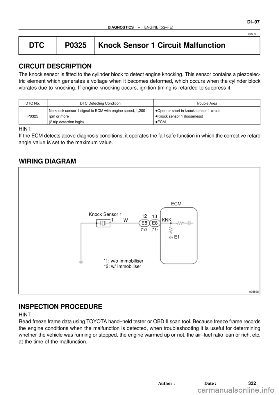
CIRCUIT DESCRIPTION
The knock sensor is fitted to the cylinder block to detect engine knocking. This sensor contains a piezoelec-
tric element which generates a voltage when it becomes deformed, which occurs when the cylinder block
vibrates due to knocking. If engine knocking occurs, ignition timing is retarded to suppress it.
DTC No.DTC Detecting ConditionTrouble Area
P0325
No knock sensor 1 signal to ECM with engine speed, 1,200
rpm or more
(2 trip detection logic)�Open or short in knock sensor 1 circuit
�Knock sensor 1 (looseness)
�ECM
HINT:
If the ECM detects above diagnosis conditions, it operates the fail safe function in which the corrective retard
angle value is set to the maximum value.
WIRING DIAGRAM
INSPECTION PROCEDURE
HINT:
Read freeze frame data using TOYOTA hand±held tester or OBD II scan tool. Because freeze frame records
the engine conditions when the malfunction is detected, when troubleshooting it is useful for determining
whether the vehicle was running or stopped, the engine warmed up or not, the air±fuel ratio lean or rich, etc.
at the time of the malfunction.
DI012±10
Page 1312 of 4592

A03599
ECM
G+
NE+
NE±
E1 E9
E9
E95
4
17 B±W
L
B±R
L BR Camshaft Position Sensor
Crankshaft Position Sensor1
2
1
2
*1: w/o Immobiliser
*2: w/ Immobiliser(*1) (*2)
E10
E10
E1012 11
6
(*1) (*2)(*1) (*2)
B±R DI±100
± DIAGNOSTICSENGINE (5S±FE)
335 Author�: Date�:
DTC P0335 Crankshaft Position Sensor ºAº Circuit
Malfunction
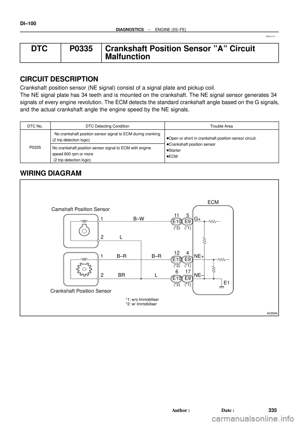
CIRCUIT DESCRIPTION
Crankshaft position sensor (NE signal) consist of a signal plate and pickup coil.
The NE signal plate has 34 teeth and is mounted on the crankshaft. The NE signal sensor generates 34
signals of every engine revolution. The ECM detects the standard crankshaft angle based on the G signals,
and the actual crankshaft angle the engine speed by the NE signals.
DTC No.DTC Detecting ConditionTrouble Area
No crankshaft position sensor signal to ECM during cranking
(2 trip detection logic)�Open or short in crankshaft position sensor circuit.
C k h ft itiP0335No crankshaft position sensor signal to ECM with engine
speed 600 rpm or more
(2 trip detection logic)�Crankshaft position sensor
�Starter
�ECM
WIRING DIAGRAM
DI013±10