Page 2501 of 4592

I08462
ECM
OD120
E4
S26
E6L±BY±B
J19
J/C
B
L±BBCruise Control ECU
14
C16OD
ECT 7
IG2
ECT No.2
SolenoidL±B L±B6
C16
± DIAGNOSTICSCRUISE CONTROL SYSTEM
DI±349
Electronically Controlled Transmission Communication Circuit
CIRCUIT DESCRIPTION
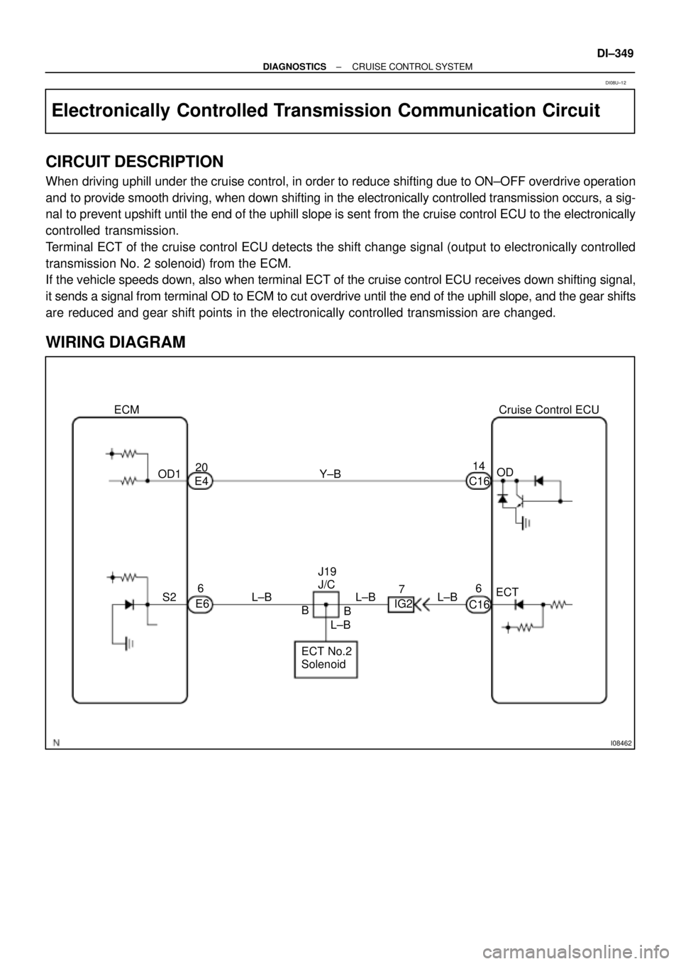
When driving uphill under the cruise control, in order to reduce shifting due to ON±OFF overdrive operation
and to provide smooth driving, when down shifting in the electronically controlled transmission occurs, a sig-
nal to prevent upshift until the end of the uphill slope is sent from the cruise control ECU to the electronically
controlled transmission.
Terminal ECT of the cruise control ECU detects the shift change signal (output to electronically controlled
transmission No. 2 solenoid) from the ECM.
If the vehicle speeds down, also when terminal ECT of the cruise control ECU receives down shifting signal,
it sends a signal from terminal OD to ECM to cut overdrive until the end of the uphill slope, and the gear shifts
are reduced and gear shift points in the electronically controlled transmission are changed.
WIRING DIAGRAM
DI08U±12
Page 2504 of 4592
I08463
R±LJ19
J/C
DD
R±LPNP Switch
210
B±R9
IG2
B±RJ22
J/C
B±R3
C16Cruise Control ECU
D
R±LR±L 2
IG2F
J24 J24J/C
FInstrument Panel J/B
1
1
1J 1KGAUGE
B±Y
Ignition Switch
AM1 IG1
24
W Instrument Panel J/B
12
1B 1K
B±R
1
F14FL BLOCK
ALT1
F9
B±GFL MAIN
Battery AM1AA DI±352
± DIAGNOSTICSCRUISE CONTROL SYSTEM
Park/Neutral Position Switch Circuit
CIRCUIT DESCRIPTION
When the shift position is except D, a signal is sent from the park/neutral position switch to the ECU. When
this signal is input during cruise control driving, the ECU cancels the cruise control.
WIRING DIAGRAM
DI08V±12
Page 2507 of 4592
I08464
Ignition Switch
24
AM1IG1
B±YInstrument Panel J/B
1
1K
B±G
FL MAIN
BatteryECU±IG
1J9
B±RCCJ12
J/C
B±RCruise Control ECU
9
C16
B
GND W
FL BLOCK
1
F91
F14
B±RInstrument Panel J/B
1
1B2
1K AM1
IFJ9
J/C
W±BA
1J7 Instrument Panel J/B
1J8
W±BAA J/C
J6J7
W±B16
C16
± DIAGNOSTICSCRUISE CONTROL SYSTEM
DI±355
ECU Power Source Circuit
CIRCUIT DESCRIPTION
The ECU power source supplies power to the actuator and sensors, etc, when terminal GND and the cruise
control ECU case are grounded.
WIRING DIAGRAM
DI08X±12
Page 2510 of 4592
AB0119
I00145
I00177
ON
CMS
(±) (+)
DI±358
± DIAGNOSTICSCRUISE CONTROL SYSTEM
Main Switch Circuit (Cruise Control Switch)
CIRCUIT DESCRIPTION
When the cruise control main switch is turned OFF, the cruise control does not operate.
WIRING DIAGRAM
See page DI±340.
INSPECTION PROCEDURE
1 Check voltage between terminal CMS of cruise control ECU connector and body
ground.
PREPARATION:
(a) Remove the ECU with connector still connected.
(b) Turn ignition switch ON.
CHECK:
Measure voltage between terminal CMS of cruise control ECU
connector when main switch is held ON and OFF.
OK:
Main switchVoltage
OFF10 ± 14 V
ONBelow 0.5 V
OK Proceed to next circuit inspection shown on
problem symptoms table (See page DI±328).
NG
DI08Z±17
Page 2512 of 4592
I08465
Battery FL MAINB±G1
F9FL BLOCK
ALT1
F14 R±L
Instrument Panel J/B
2
1D
1K1
GAUGE
B±YIgnition Switch
4 IG1 AM1 2
W
B±RInstrument Panel J/B
1
1BAM12
1K CRUISE MAIN
Indicator Light
(in Combination Meter)
D DJ/CJ3
R±L10 7
C12 C12IE25
OODD
O J/CJ1
4
C16
Cruise Control ECU
PI DI±360
± DIAGNOSTICSCRUISE CONTROL SYSTEM
CRUISE MAIN Indicator Light Circuit
CIRCUIT DESCRIPTION
When the cruise control main switch is turned ON, CRUISE MAIN indicator light lights up.
WIRING DIAGRAM
DI090±20
Page 2514 of 4592
I00291
Cruise Control ECU
4
PI
5
TC O
LG±R D DJ/C
J/C
B
B B O
LG±R 10
4DLC2
IG3 11
C16
LG±R 11 DLC1
C16
J1
D2 D2
J2
D1LG±R DI±362
± DIAGNOSTICSCRUISE CONTROL SYSTEM
Diagnosis Circuit
CIRCUIT DESCRIPTION
This circuit sends a signal to the ECU that outputs DTC.
WIRING DIAGRAM
DI091±12
Page 2832 of 4592

V08423 Knock Sensor 1
GRECM
KNK
E1 12
E6
WIRING DIAGRAM
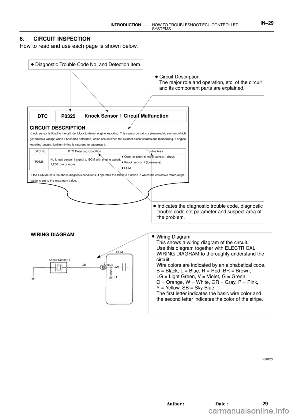
Wiring Diagram
This shows a wiring diagram of the circuit.
Use this diagram together with ELECTRICAL
WIRING DIAGRAM to thoroughly understand the
circuit.
Wire colors are indicated by an alphabetical code.
B = Black, L = Blue, R = Red, BR = Brown,
LG = Light Green, V = Violet, G = Green,
O = Orange, W = White, GR = Gray, P = Pink,
Y = Yellow, SB = Sky Blue
The first letter indicates the basic wire color and
the second letter indicates the color of the stripe.
DTC P0325Knock Sensor 1 Circuit Malfunction
CIRCUIT DESCRIPTION
Knock sensor is fitted to the cylinder block to detect engine knocking. This sensor contains a piezoelectric element which
generates a voltage when it becomes deformed, which occurs when the cylinder block vibrates due to knocking. If engine
knocking occurs, ignition timing is retarded to suppress it.
DTC No. DTC Detecting Condition Trouble Area
P0325No knock sensor 1 signal to ECM with engine speed,
1,200 rpm or more.� Open or short in knock sensor1 circuit
� Knock sensor 1 (looseness)
� ECM
If the ECM detects the above diagnosis conditions, it operates the fall safe function in which the corrective retard angle
value is set to the maximum value.
� Diagnostic Trouble Code No. and Detection Item
� Circuit Description
The major role and operation, etc. of the circuit
and its component parts are explained.
� Indicates the diagnostic trouble code, diagnostic
trouble code set parameter and suspect area of
the problem.
�
± INTRODUCTIONHOW TO TROUBLESHOOT ECU CONTROLLED
SYSTEMSIN±29
29 Author�: Date�:
6. CIRCUIT INSPECTION
How to read and use each page is shown below.
Page 2873 of 4592

V08423 Knock Sensor 1
GRECM
KNK
E1 12
E6
WIRING DIAGRAM
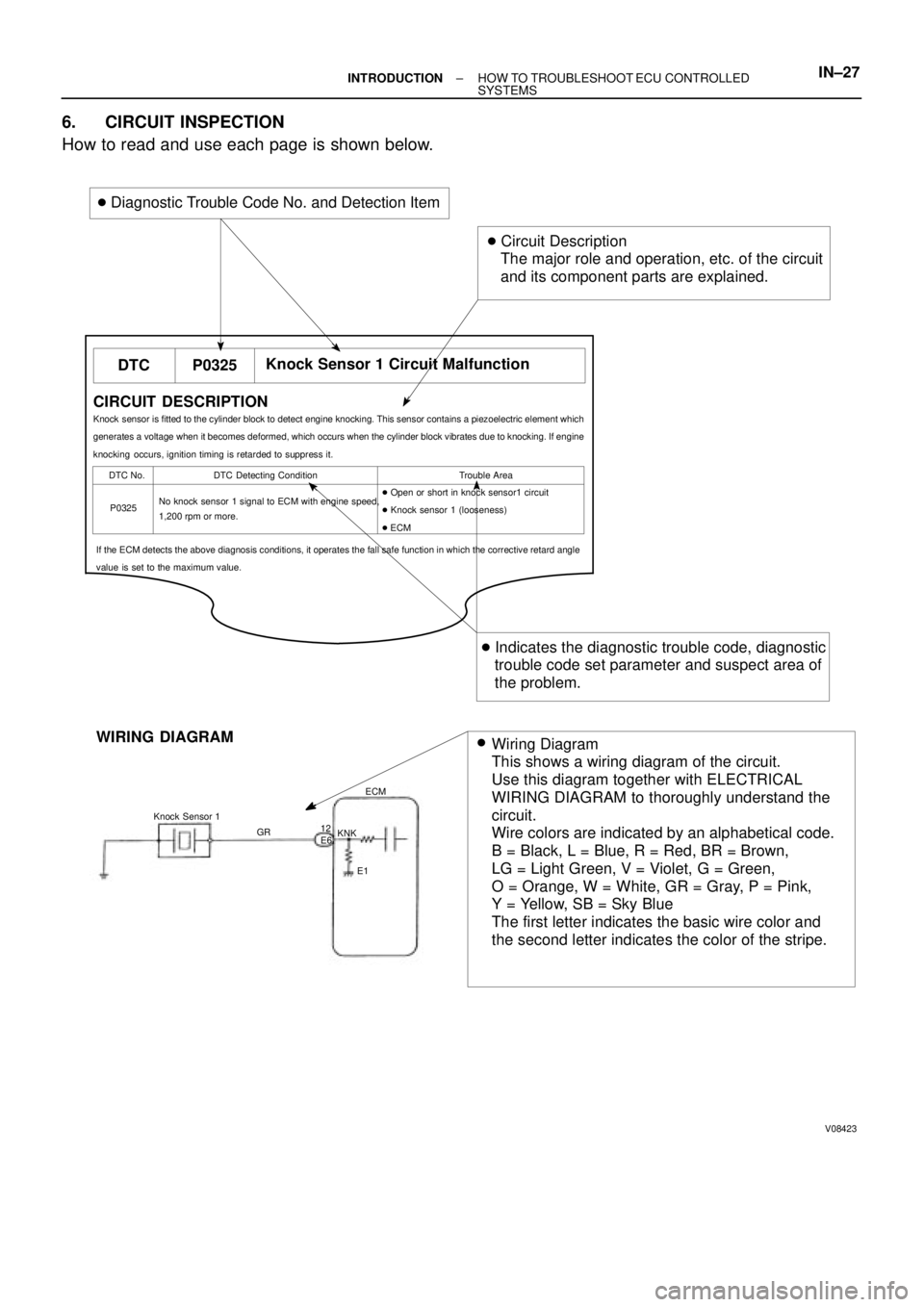
Wiring Diagram
This shows a wiring diagram of the circuit.
Use this diagram together with ELECTRICAL
WIRING DIAGRAM to thoroughly understand the
circuit.
Wire colors are indicated by an alphabetical code.
B = Black, L = Blue, R = Red, BR = Brown,
LG = Light Green, V = Violet, G = Green,
O = Orange, W = White, GR = Gray, P = Pink,
Y = Yellow, SB = Sky Blue
The first letter indicates the basic wire color and
the second letter indicates the color of the stripe.
DTC P0325Knock Sensor 1 Circuit Malfunction
CIRCUIT DESCRIPTION
Knock sensor is fitted to the cylinder block to detect engine knocking. This sensor contains a piezoelectric element which
generates a voltage when it becomes deformed, which occurs when the cylinder block vibrates due to knocking. If engine
knocking occurs, ignition timing is retarded to suppress it.
DTC No. DTC Detecting Condition Trouble Area
P0325No knock sensor 1 signal to ECM with engine speed,
1,200 rpm or more.� Open or short in knock sensor1 circuit
� Knock sensor 1 (looseness)
� ECM
If the ECM detects the above diagnosis conditions, it operates the fall safe function in which the corrective retard angle
value is set to the maximum value.
� Diagnostic Trouble Code No. and Detection Item
� Circuit Description
The major role and operation, etc. of the circuit
and its component parts are explained.
� Indicates the diagnostic trouble code, diagnostic
trouble code set parameter and suspect area of
the problem.
�
± INTRODUCTIONHOW TO TROUBLESHOOT ECU CONTROLLED
SYSTEMSIN±27
6. CIRCUIT INSPECTION
How to read and use each page is shown below.