Page 2481 of 4592
DI08M±13
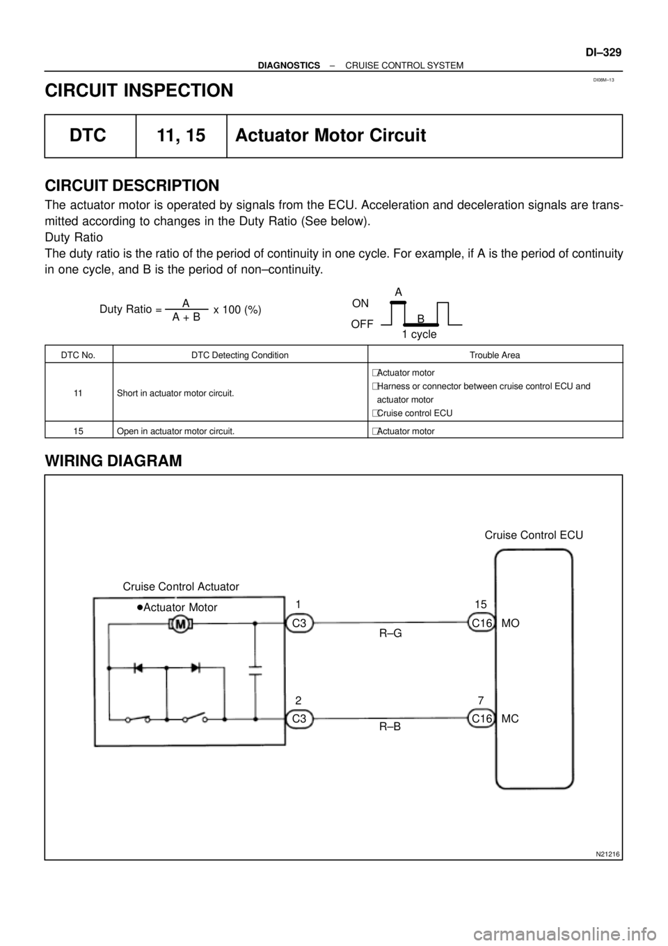
Duty Ratio =A + BA
x 100 (%)
ON
OFFA
B
1 cycle
N21216
Cruise Control ECU
MO
7
MC
R±B Cruise Control Actuator
R±G 1
215
�Actuator Motor
C3
C3C16
C16
± DIAGNOSTICSCRUISE CONTROL SYSTEM
DI±329
CIRCUIT INSPECTION
DTC 11, 15 Actuator Motor Circuit
CIRCUIT DESCRIPTION
The actuator motor is operated by signals from the ECU. Acceleration and deceleration signals are trans-
mitted according to changes in the Duty Ratio (See below).
Duty Ratio
The duty ratio is the ratio of the period of continuity in one cycle. For example, if A is the period of continuity
in one cycle, and B is the period of non±continuity.
DTC No.DTC Detecting ConditionTrouble Area
11Short in actuator motor circuit.
�Actuator motor
�Harness or connector between cruise control ECU and
actuator motor
�Cruise control ECU
15Open in actuator motor circuit.�Actuator motor
WIRING DIAGRAM
Page 2483 of 4592

I00281
Cruise Control ECU
C16
G±B
2 1 34W±B
3
STOP Fuse8 Stop Light Switch
4
R±Y
Stop Lights Cruise Control Actuator
� Actuator Magnetic Clutch
J6
J6AAJ/C
W±B
1J
1J
W±B
A
J/C
IF 8
7
J9Instrument
Panel J/BL
± DIAGNOSTICSCRUISE CONTROL SYSTEM
DI±331
DTC 12 Actuator Magnetic Clutch Circuit
CIRCUIT DESCRIPTION
This circuit turns on the magnetic clutch inside the actuator during cruise control operation according to the
signal from the ECU. If a malfunction occurs in the actuator or speed sensor, etc. during cruise control opera-
tion, the rotor shaft between the motor and control plate is released.
When the brake pedal is depressed, the stop light switch turns on, supplying electrical power to the stop light.
Power supply to the magnetic clutch is mechanically cut and the magnetic clutch is turned OFF.
When driving downhill, if the vehicle speed exceeds the set speed by 15 km/h (9 mph), the ECU turns the
safety magnet clutch OFF. If the vehicle speed later drops to within 10 km/h (6 mph), cruise control at the
set speed is resumed.
DTC No.DTC Detecting ConditionTrouble Area
12Short in actuator magnetic clutch circuit.
Open (0.8 sec.) in actuator magnetic clutch circuit.
�STOP Fuse
�Stop light switch
�Actuator magnetic clutch
�Harness or connector between cruise control ECU and
actuator magnetic clutch, actuator magnetic clutch and body
ground
�Cruise control ECU
WIRING DIAGRAM
DI08N±13
Page 2486 of 4592
I00055
4
3(+)
(±)
DI±334
± DIAGNOSTICSCRUISE CONTROL SYSTEM
DTC 14 Actuator Mechanical Malfunction
CIRCUIT DESCRIPTION
The circuit detects the rotation position of the actuator control plate and sends a signal to the ECU.
DTC No.DTC Detecting ConditionTrouble Area
14Cruise control actuator mechanical malfunction.
�Actuator lock: (motor, arm)
�Actuator motor
�Cruise control ECU
WIRING DIAGRAM
See page DI±329.
INSPECTION PROCEDURE
1 Check cruise control actuator arm locking operation
PREPARATION:
(a) Turn ignition switch OFF.
(b) Disconnect the actuator connector.
CHECK:
Connect the positive (+) lead from the battery to the terminal 3
of actuator and the negative (±) lead to terminal 4.
NOTICE:
Do not connect the high tension cables to the wrong bat-
tery terminal. The cruise control actuator will be damaged.
Move the control plate by hand.
OK:
Control plate doesn't move.
NG Replace cruise control actuator.
OK
DI08O±13
Page 2488 of 4592

I00292
Vehicle Speed Sensor
ECUCombination Meter
Cruise Control ECU
4 pulses/
1 rotation
of rotor shaft4 pulses/
1 rotation
of rotor shaft
I00282
Cruise Control ECU
12
SPDV±W V±WB
BJ15
J/CIF1
3
V±W14
Combination Meter
15
6
Speedo
±meter
P L
IH12IH17
P
3L
2
SI
SE
IG+
1
R±Lto GAUGE Fuse
C16
C11 C11
C12
Speed
Sensor DI±336
± DIAGNOSTICSCRUISE CONTROL SYSTEM
DTC 21 Open in Vehicle Speed Sensor Circuit
CIRCUIT DESCRIPTION
The signal from the vehicle speed sensor circuit is sent to cruise control ECU as vehicle speed signal.
The rotor shaft is driven by the gear of the transmission.
For each rotation of the shaft, the vehicle speed sensor sends a 4±pulse signal through the combination
meter to the cruise control ECU (See the following installation).
This signal is converted inside the combination meter and sent as a 4±pulse signal to the cruise control ECU.
The ECU calculates the vehicle speed from this pulse frequency.
DTC No.DTC Detecting ConditionTrouble Area
21Speed signal is not input to the cruise control ECU while cruise
control is set.
�Combination meter
�Harness or connector between cruise control ECU and com-
bination meter, combination meter and vehicle speed sensor
�Vehicle speed sensor
�Cruise control ECU
WIRING DIAGRAM
DI08P±13
Page 2491 of 4592
± DIAGNOSTICSCRUISE CONTROL SYSTEM
DI±339
DTC 23 Vehicle Speed Signal Abnormal
CIRCUIT DESCRIPTION
See page DI±336.
DTC No.DTC Detecting ConditionTrouble Area
23Vehicle speed sensor pulse is abnormal.�Vehicle speed sensor
�Cruise control ECU
WIRING DIAGRAM
See page DI±336.
INSPECTION PROCEDURE
1 Check vehicle speed sensor (See Pub. No. RM654U on page BE±47).
NG Replace vehicle speed sensor.
OK
Check and replace cruise control ECU
(See page IN±29).
DI08Q±11
Page 2492 of 4592
I00283
Cruise Control ECU
CMS
CCS
GND
CMS
W±L
W±B
W Cruise Control Switch
� Main Switch
� Control Switch
1J
78
W±B5
4
3
W±B MAIN
CANCEL
SET/COAST
RES/ACC
A11
10
16 CCS
EP
J6
J6J7 AJ/C
A
A
1J
W±B J/C
IFC16
C16
C16
J9
Instrument Panel J/B DI±340
± DIAGNOSTICSCRUISE CONTROL SYSTEM
DTC 32 Control Switch Circuit (Cruise Control
Switch)
CIRCUIT DESCRIPTION
This circuit carries the SET/COAST, RESUME/ACCEL and CANCEL signals (each voltage) to the ECU.
DTC No.DTC Detecting ConditionTrouble Area
32Short in control switch circuit.
�Cruise control switch
�Harness or connector between cruise control ECU and
cruise control switch, cruise control switch and body ground
�Cruise control ECU
WIRING DIAGRAM
DI08R±13
Page 2495 of 4592
N21220
Cruise Control ECU
IDL 13
L±R ECM
IDLOE43
C16
± DIAGNOSTICSCRUISE CONTROL SYSTEM
DI±343
DTC 51 Idle Signal Circuit
CIRCUIT DESCRIPTION
When the idle switch is turned ON, a signal is sent to the ECU. The ECU uses this signal to correct the dis-
crepancy between the throttle valve position and the actuator position sensor value to enable accurate
cruise control at the set speed. If the idle switch is malfunctioning, problem symptoms also occur in the en-
gine, so also inspect the engine.
DTC No.DTC Detecting ConditionTrouble Area
51Short in idle signal circuit.
�Harness or connector between ECM and throttle position
sensor
�Throttle position sensor
�Harness or connector between cruise control ECU and ECM
�Cruise control ECU
WIRING DIAGRAM
DI08S±11
Page 2498 of 4592

I08461
A
J6A
J6 J/C
J/CJ9
A
W±BW±B
Instrument Panel J/B
7
1J
1J8
IF Battery FL MAIN B±G1
F9FL BLOCK
ALT
F141B±R 7
1C4
1B Instrument Panel J/B
STOP W2
3Stop Light Switch
1
4G±W1R4 Instrument Panel J/B
5
1R
R±Y
G±B
W±BCruise Control
Actuator
3
4G±WAA J23
J/C
G±W2
C16
C16
8Cruise Control ECU
STP±
L
DI±346
± DIAGNOSTICSCRUISE CONTROL SYSTEM
Stop Light Switch Circuit
CIRCUIT DESCRIPTION
When the brake pedal is depressed, the stop light switch sends a signal to the ECU. When the ECU receives
this signal, it cancels the cruise control.
A fail±safe function is provided so that the cancel functions normally, even if there is a malfunction in the stop
light signal circuit.
The cancel conditions are: Battery positive voltage at terminal STP±
When the brake is ON, battery positive voltage normally is applied through the STOP fuse and stop light
switch to terminal STP± of the ECU, and the ECU turns the cruise control OFF.
If the harness connected to terminal STP± has an open circuit, terminal STP± will have battery positive volt-
age and the cruise control will be turned OFF.
Also, when the brake is ON, the magnetic clutch circuit is cut mechanically by the stop light switch, turning
the cruise control OFF. (See page DI±331 for operation of the magnetic clutch)
WIRING DIAGRAM
DI08T±12

(±)
DI±334
± DIAGNOSTICSCRUISE CONTROL SYSTEM
DTC 14 Actuator Mechanical Malfunction
CIRCUIT DESCRIPTION
The circuit detects the rotation position of the actuator control plate and se")