Page 2076 of 4592
I04444
Theft Deterrent ECU
DSWD
CTY
DSWP
4
T4
T4
T41
5 R±G A
J10 C
R±G 1
1G 7
1S
Integration
Relay
4
1G R±G
Door Courtesy
Switch Front LH
1
R±W J/C
E
J34 D
J33
D
J33
D J33 6
4
12
1S R±B
1 Door Courtesy
Switch Rear LH
J9
R±W
R±W 8
IN2 R±W
1 Door Courtesy
Switch Rear RH
R±W
1
Diode
2
R±G J/C
E
J33
J34D
E
J33R±G R±G
IN26
R±G
1 Door Courtesy
Switch Front RH
J/C
Instrument panel J/B DI±864
± DIAGNOSTICSTHEFT DETERRENT SYSTEM
1099 Author�: Date�:
Door Courtesy Switch Circuit
CIRCUIT DESCRIPTION
The door courtesy switch goes ON when the door is opened and goes OFF when the door is closed.
WIRING DIAGRAM
DI075±06
Page 2172 of 4592

DI00L±08
± DIAGNOSTICSENGINE
DI±21
PROBLEM SYMPTOMS TABLE
SymptomSuspect AreaSee page
Engine does not crank (Does not start)6. Starter
7. Starter relay*1
*2
No initial combustion (Does not start)
1. ECM power source circuit
2. Fuel shutoff valve circuit
3. ECMDI±116
DI±86
IN±29
No complete combustion (Does not start)1. Fuel shutoff valve circuitDI±86
Engine cranks normally (Difficult to start)
1. Starter signal circuit
2. Fuel shutoff valve circuit
3. CompressionDI±113
DI±86
EM±3
Cold engine (Difficult to start)1. Starter signal circuit
2. Fuel shutoff valve circuitDI±113
DI±86
Hot engine (Difficult to start)1. Starter signal circuit
2. Fuel shutoff valve circuitDI±113
DI±86
High engine idle speed (Poor idling)1. A/C switch circuit
2. ECM power source circuit*3
DI±116
Low engine idle speed (Poor idling)1. A/C switch circuit
2. Fuel shutoff valve circuit*3
DI±86
Rough idling (Poor idling)1. Compression
2. Fuel shutoff valve circuitEM±3
DI±86
Hunting (Poor idling)1. ECM power source circuit
2. Fuel shutoff valve circuitDI±116
DI±86
Hesitation/Poor acceleration (Poor driveability)1. Fuel shutoff valve circuit
2. A/T faultyDI±86
DI±148
Surging (Poor driveability)1. Fuel shutoff valve circuitDI±86
Soon after starting (Engine stall)1. Fuel shutoff valve circuitDI±86
During A/C operation (Engine stall)1. A/C switch circuit
2. ECM*3
IN±29
A/C switch indicatior blinking1. A/C Compressor lock sensor circuit
2. A/C Evaporator temp. sensor circuitDI±119
DI±121
*1: See Pub. No. RM654U, page ST±2.
*2: See Pub. No. RM654U, page ST±20.
*3: See Pub. No. RM654U, page AC±84.
Page 2192 of 4592

A09395
B±Y
FL
Block47
EFI
IGN
14 2
4 EFI
Relay
21
53
B±Y
3
12 B
B
1
243 9
IG1B
W±R
P±B
G
P±B 56
2
5
1K
14
HT2 21 1W
E4E5
E6E5
MAIN FLE5 1B
B 1ECM
AF+
OX2 HTAF
AF± 1K
2F
E03 E1E04 A/F
Sensor
Engine Room R/B No.2
B±YJ18 J/C
2
1
IG3IG3
IG3
EB
EC
Instrument
Panel J/B7
3 5
6
7
2L 2A
F1111
F9
B±G
Battery B±R
2K
2J
W±B
3.3V
3.0V
AM2 B
W±R
to Analog±Digital
Converter
B±Y B±Y
IG Switch
B±R
2 E
E
J23 J/C
B
BB±YL
B±W
BR
(*1)
J23 J/C
Heated
Oxygen
Sensor
(Bank 1
Sensor 2)
B
IG17G
BR
BR
J20
J/C A
A
± DIAGNOSTICSENGINE
DI±41
�
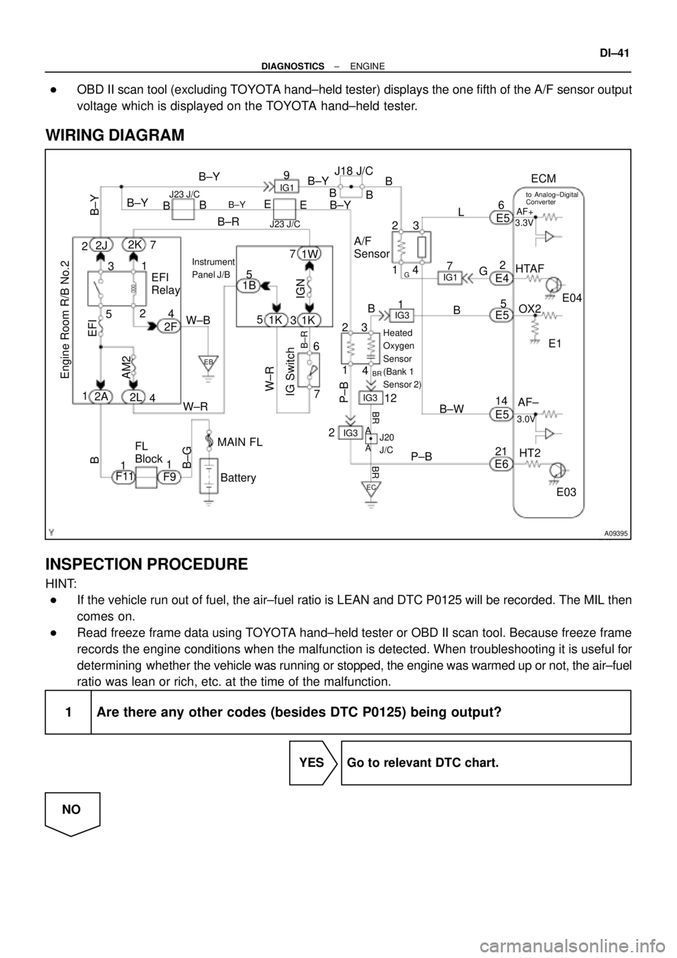
OBD II scan tool (excluding TOYOTA hand±held tester) displays the one fifth of the A/F sensor output
voltage which is displayed on the TOYOTA hand±held tester.
WIRING DIAGRAM
INSPECTION PROCEDURE
HINT:
�If the vehicle run out of fuel, the air±fuel ratio is LEAN and DTC P0125 will be recorded. The MIL then
comes on.
�Read freeze frame data using TOYOTA hand±held tester or OBD II scan tool. Because freeze frame
records the engine conditions when the malfunction is detected. When troubleshooting it is useful for
determining whether the vehicle was running or stopped, the engine was warmed up or not, the air±fuel
ratio was lean or rich, etc. at the time of the malfunction.
1 Are there any other codes (besides DTC P0125) being output?
YES Go to relevant DTC chart.
NO
Page 2199 of 4592
DI±48
± DIAGNOSTICSENGINE
2 Check resistance of heated oxygen sensor heater (See Pub. No. RM654U, page
SF±63).
NG Replace heated oxygen sensor.
OK
Check and repair harness or connector between EFI main relay (Marking: EFI) and heated oxygen
sensor, and heated oxygen sensor and ECM (See page IN±29).
Page 2215 of 4592

A09397
ECM
J18
J/C
7 From
Battery
B
213
EFI Relay VSV
for EGR
21P-B23
E6EGR
E01
2K2
2J EFI
Engine Room J/B No.2 1B 9
B-Y
B
2AB-Y
IG3
EB
W-B
2F4B-Y
5
B-YFrom
Ignition SW
P20769
Vehicle Speed
60 ± 80 km/h
(38 ± 50 mph)
Idling
IG SW OFF
(1)(2)
Warm up
3 ± 5 min.2 min.
3 ± 5 min.Time (3)
(4)
(5)(6)
(7)
2 min. DI±64
± DIAGNOSTICSENGINE
WIRING DIAGRAM
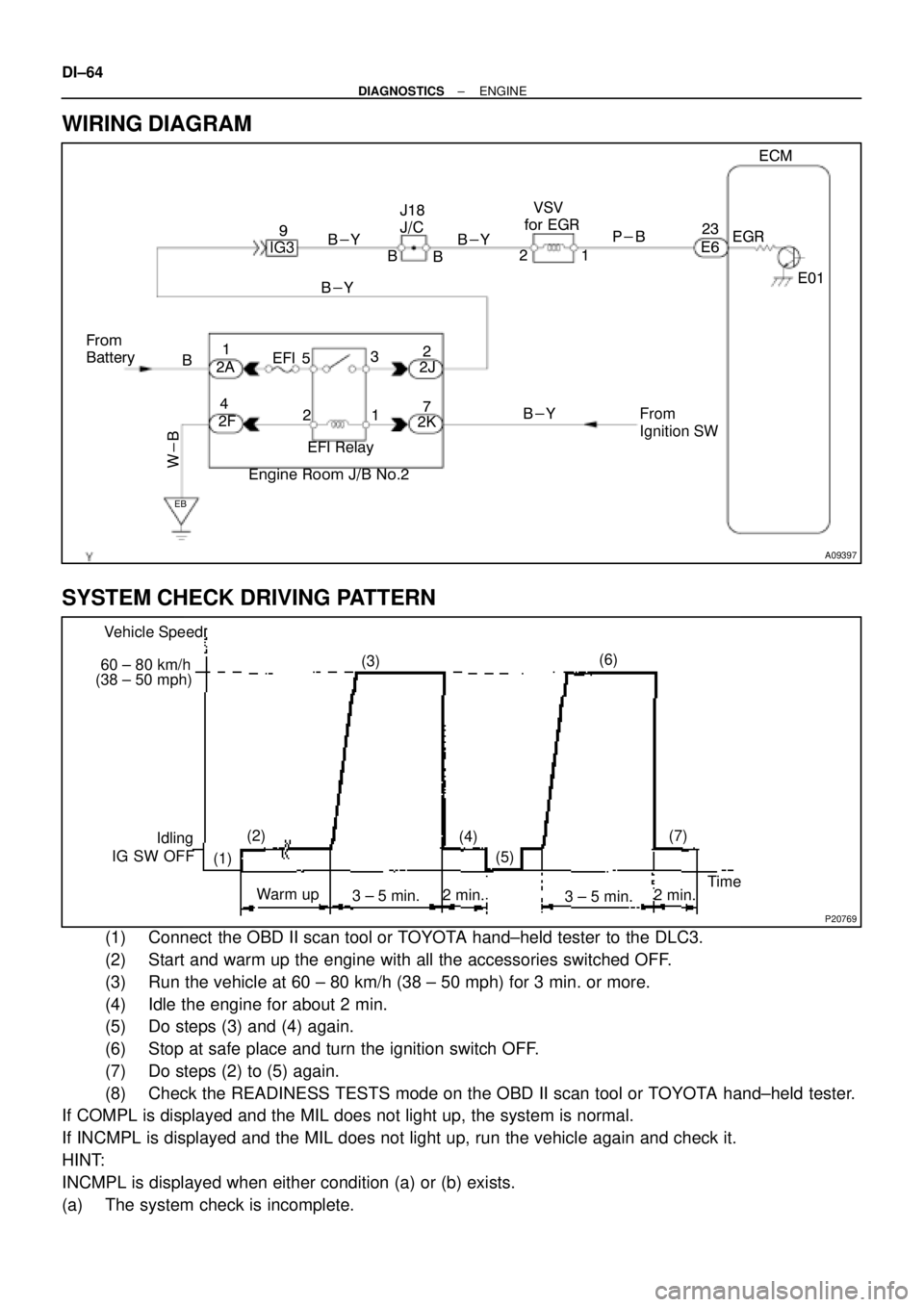
SYSTEM CHECK DRIVING PATTERN
(1) Connect the OBD II scan tool or TOYOTA hand±held tester to the DLC3.
(2) Start and warm up the engine with all the accessories switched OFF.
(3) Run the vehicle at 60 ± 80 km/h (38 ± 50 mph) for 3 min. or more.
(4) Idle the engine for about 2 min.
(5) Do steps (3) and (4) again.
(6) Stop at safe place and turn the ignition switch OFF.
(7) Do steps (2) to (5) again.
(8) Check the READINESS TESTS mode on the OBD II scan tool or TOYOTA hand±held tester.
If COMPL is displayed and the MIL does not light up, the system is normal.
If INCMPL is displayed and the MIL does not light up, run the vehicle again and check it.
HINT:
INCMPL is displayed when either condition (a) or (b) exists.
(a) The system check is incomplete.
Page 2223 of 4592

A01758
Throttle Valve
To Cylinder ECM SignalFrom
Air
Cleaner
Valve
IAC Valve
Intake Air
Chamber
A09420
Driver Side J/BEFI Relay
Engine Room R/B No.2 From
IG SwitchFrom
BatteryECM
E6 10
w
1
3 2 IAC Valve
B±Y
IG39
EB
B±Y
W±B 4
12 3 5 21EFI
B
37
1W 1KIGN
B±R
W±B
EC
RSD
7 12
2A
2J
2K
2FJ18
J/C
B B
DI±72
± DIAGNOSTICSENGINE
DTC P0505 Idle Control System Malfunction
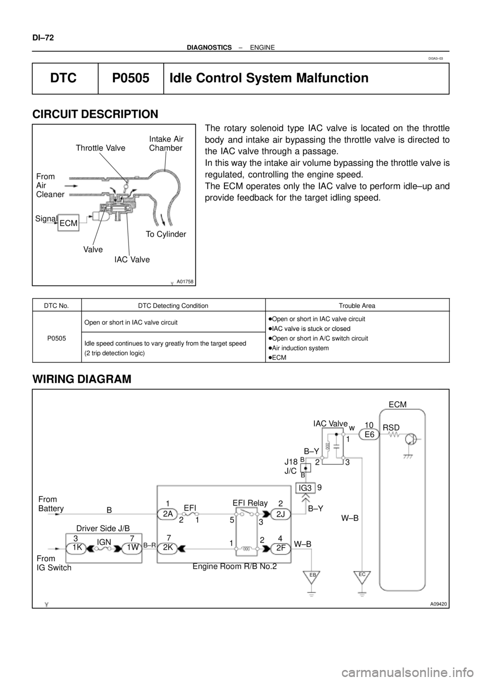
CIRCUIT DESCRIPTION
The rotary solenoid type IAC valve is located on the throttle
body and intake air bypassing the throttle valve is directed to
the IAC valve through a passage.
In this way the intake air volume bypassing the throttle valve is
regulated, controlling the engine speed.
The ECM operates only the IAC valve to perform idle±up and
provide feedback for the target idling speed.
DTC No.DTC Detecting ConditionTrouble Area
Open or short in IAC valve circuit�Open or short in IAC valve circuit
�IAC valve is stuck or closed
P0505Idle speed continues to vary greatly from the target speed
(2 trip detection logic)
�IAC valve is stuck or closed
�Open or short in A/C switch circuit
�Air induction system
�ECM
WIRING DIAGRAM
DI3A3±03
Page 2236 of 4592
± DIAGNOSTICSENGINE
DI±85
Check and repair harness or connector between EFI main relay (Marking: EFI) and A/F sensor,
and A/F sensor and ECM (See page IN±29).
Page 2238 of 4592
A09426
Battery
EFI
AM2
1 2 3
3 1J
B2A
2J Instrument Panel J/B
1B 1W
37
15
IG Switch
1
B±RST Relay EFI Relay
5
6 3
11 410
4
5 4
5
A 2B STARTER
II23
B±W
II2
11
Starter
Park/Neutral
Position Switch
5 7
B±R Engine Room J/B No.2
2C
2F IGN
FL Block1
2D1
MAIN
W±B
10B
C
1
CIR
OPN
Relay
IGG±R
14
2L
E4FCECM
E01 1
S1S2
Engine Room R/B
No.1
2
J40
J/C
G±R
L±B
5 93
L±B
R
EB B±R
GR
W±R
B±W
BL
J/CB±R
J8
2K
J7
B
1 1 1
B 1K
1K
1K
8 76
EB1
4
J11
J/CF6 1
W±R
MAIN
FL2K
2
B±RB
B F41
GR
A
EB1
55
W±BW±B
GR
Fuel ShutOff Valve For
Pressure Regulator
Fuel ShutOff Valve
For Fuel TankFuel ShutOff Valve
For Delivery Pipe
ID1
7 J29
J/C
B
B±W
VCNG2VCNG3 4
E7
9
E7
13
E6 2
2J21
II39
II4
6 J19
J/C
B
B±G
21
21
L±B L±B
EC
L±B L±B
Y±G
W±B B±Y B±Y
BB±Y
P
± DIAGNOSTICSENGINE
DI±87
WIRING DIAGRAM