Page 2049 of 4592

DI06R±06
Details of Problem
The theft deterrent system cannot be set
Inspecting Circuit*1See page
DI±838 1. Indicator light circuit
2. ECU power source circuit
3. Key unlock warning switch circuit
7. Door courtesy switch circuit
8. Door unlock detection switch circuit
9. Engine hood courtesy switch circuit
The indicator light does not blink when system is setIndicator light circuit
When the
system is
set
When the rear doors are unlocked
When the luggage compartment door is opened
by a method other than the key4. Luggage compartment door key
lock and unlock switch circuit
5. Luggage compartment door
courtesy switch circuit
When the engine hood is opened
The system
does not
operateDoor unlock detection switch circuit
Luggage compartment door
courtesy switch circuit
Engine hood courtesy switch circuit
While the system is
in warning operation
Horns do not sound
Theft deterrent horn does not sound
Headlights do not flash
Taillights do not flash
The door lock is not locked in unlock conditionHorn relay circuit
Theft deterrent horn circuit
Headlight control relay circuit
Taillight control relay circuit
Door unlock detection switch circuit
6. Door key lock and unlock switch
circuit
It is not canceled when the ignition key is turned to
ACC or ON position
It still operates when the luggage compartment door is
opened with the key When the
system is
set
Ignition switch circuit
Luggage compartment door key
lock and unlock switch circuit
System is still set even when a rear door is open
Door courtesy switch circuit
Even when the
system is not
setHorns sound
Theft deterrent horn sounds
Headlights stay on
Taillights stay onHorn relay circuit
Theft deterrent horn circuit
Headlight control relay circuit
Taillight control relay circuit
DI±840
DI±853
DI±855
DI±858
DI±855
DI±864
DI±862
DI±866
DI±838
DI±862
DI±858
DI±866
DI±845
DI±843
DI±847
DI±849
DI±862
DI±851
DI±855
DI±864
DI±845
DI±843
DI±847
DI±849
*1: If numbers are given to the circuit proceed with troubleshooting in the order indicated by those numbers.
± DIAGNOSTICSTHEFT DETERRENT SYSTEM
DI±837
1072 Author�: Date�:
PROBLEM SYMPTOMS TABLE
Proceed to the reference page shown in the matrix chart below for each malfunction symptom and trouble-
shoot for each circuit.
HINT:
Troubleshooting of the theft deterrent system is based on the premise that the door lock control system is
operating normally. Accordingly, before troubleshooting the theft deterrent system, first make certain that
the door lock control system is operating normally.
Page 2055 of 4592
I00261
Theft Deterrent ECU
SH
T39
W±L IG3
5
W±L IK1
4
W±L
HORN
1 2
W
3
2F
HORN
1
2A
E/G Room J/B No.2
B F6 F4
FL BLOCK
B±G
FL MAIN
Battery1
1
± DIAGNOSTICSTHEFT DETERRENT SYSTEM
DI±843
1078 Author�: Date�:
Theft Deterrent Horn Circuit
CIRCUIT DESCRIPTION
When the theft deterrent system is activated, the relay in the ECU turns ON and OFF cycles of approximately
0.2 sec., causing the theft deterrent horn to blow (See the wiring diagram below).
In this condition, if any of the following operations is done, the relay in the ECU turns OFF, thus stopping
the theft deterrent horn from blowing:
(1) Unlock the front LH or RH door with key.
(2) Turn the ignition switch to ACC or ON position.
(3) Unlock the doors with the wireless door lock control system.
(4) Wait for approximately 60 seconds.
(5) Push the panic switch of the wireless door lock control system.
WIRING DIAGRAM
DI06V±06
Page 2057 of 4592
I00262
Theft Deterrent ECU
HORN
T3
12
G±B IG1
11
G±B
C CJ/C J2
G±B
G±W1
1
Horn
E/G Room J/B No.2
HORN Relay
31
2F
10
2K2 5
1 HORN
12A
B
1
F6
FL BLOCK
1
F4
B±G
FL MAIN
Battery
± DIAGNOSTICSTHEFT DETERRENT SYSTEM
DI±845
1080 Author�: Date�:
Horn Relay Circuit
CIRCUIT DESCRIPTION
When the theft deterrent system is activated, it causes the Tr in the ECU to switch ON and OFF in approxi-
mately 0.4 sec. cycles. This switches the horn relay ON and OFF, thus the horns blow (See the wiring dia-
gram below).
In this condition, if any of the following operations is done, the Tr in the ECU goes off and the horn relay
switches off, thus stopping the horns from blowing:
(1) Unlock the front LH or RH door with key.
(2) Turn the ignition switch to ACC or ON position.
(3) Unlock the doors with the wireless door lock control system.
(4) Wait for approximately 60 seconds.
(5) Push the panic switch of the wireless door lock control system.
WIRING DIAGRAM
DI06W±06
Page 2058 of 4592
I01923
HORN
DI±846
± DIAGNOSTICSTHEFT DETERRENT SYSTEM
1081 Author�: Date�:
INSPECTION PROCEDURE
HINT:
The flow chart below is based on the premise that the horns blow normally whenever the horn switch is oper-
ated. If horn operation is not normal when the horn switch is operated, check the horn switch.
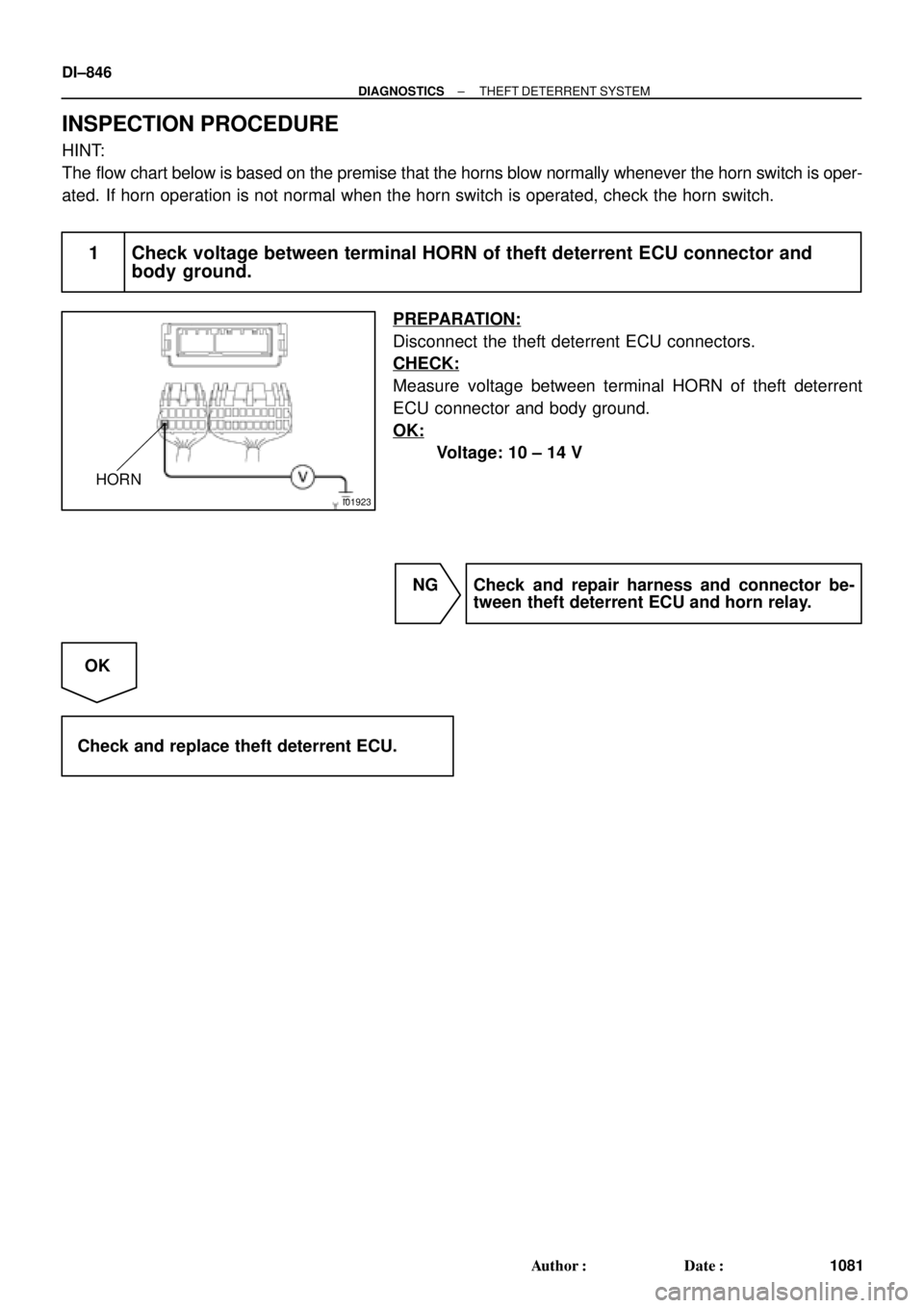
1 Check voltage between terminal HORN of theft deterrent ECU connector and
body ground.
PREPARATION:
Disconnect the theft deterrent ECU connectors.
CHECK:
Measure voltage between terminal HORN of theft deterrent
ECU connector and body ground.
OK:
Voltage: 10 ± 14 V
NG Check and repair harness and connector be-
tween theft deterrent ECU and horn relay.
OK
Check and replace theft deterrent ECU.
Page 2059 of 4592

*1
Daytime Running
Light Relay*2
Dayti")
I08428
E/G Room J/B No.2
Theft Deterrent ECU Headlight
Control Realy
FL MAIN
Battery 3
2BMAIN
HEAD R±B B
3 4
1
28
2K
32G
1
F61
F4Light Control Switch
(COMB. SW)
*1
Daytime Running
Light Relay*2
Daytime Running
Light Relay7
IG310
T3 R±B
*1
R±B*2R*2
19J32
*1
J6*2
J/C
*1: w/o Daytime Running Light
*2: w/ Daytime Running Light2BB
FL BLOCK
B±GR±B
± DIAGNOSTICSTHEFT DETERRENT SYSTEM
DI±847
1082 Author�: Date�:
Headlight Control Relay Circuit
CIRCUIT DESCRIPTION
When the theft deterrent system is activated, it causes the Tr in the ECU to switch ON and OFF at approxi-
mately 0.4 sec. intervals. This switches the headlight control relay ON and OFF, thus flashing the headlights
(See the wiring diagram below).
In this condition, if any of the following operations is done, the Tr in the ECU goes OFF and the headlight
control relay switches OFF, thus stopping the headlights flashing:
(1) Unlock the front LH or RH door with key.
(2) Turn the ignition switch to ACC or ON position.
(3) Unlock the doors with the wireless door lock control system.
(4) Wait for approximately 60 seconds.
(5) Push the panic switch of the wireless door lock control system.
WIRING DIAGRAM
DI06X±06
Page 2060 of 4592
I01924
HEAD
DI±848
± DIAGNOSTICSTHEFT DETERRENT SYSTEM
1083 Author�: Date�:
INSPECTION PROCEDURE
HINT:The flow chart below is based on the premise that the headlights light up normally whenever the light
control switch is operated. If headlight operation is not normal when the light control switch is operated, pro-
ceed to troubleshooting on page BE±2.
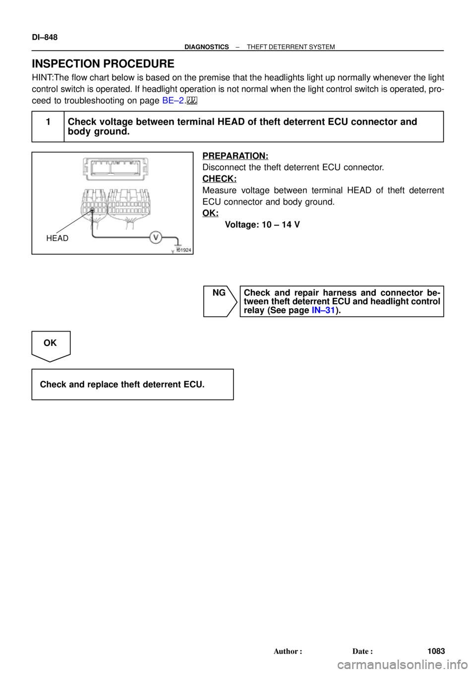
1 Check voltage between terminal HEAD of theft deterrent ECU connector and
body ground.
PREPARATION:
Disconnect the theft deterrent ECU connector.
CHECK:
Measure voltage between terminal HEAD of theft deterrent
ECU connector and body ground.
OK:
Voltage: 10 ± 14 V
NG Check and repair harness and connector be-
tween theft deterrent ECU and headlight control
relay (See page IN±31).
OK
Check and replace theft deterrent ECU.
Page 2061 of 4592

I00266
Theft Deterrent ECU
TAIL
T3
11
G±R
B BJ/C J33
G±R
10
IG1
G±RA
AJ2
J/C
G±R 1C
6
2
3
Taillight Control Relay
1
5
TAIL81S
1C
9
1B
4 Instrument Panel J/B
B±R
Light
Failure
Sensor
Turn & Clearance
Light
1F9
F4
1
FL
BLOCK
FL MAIN
Battery
B±G ALT
± DIAGNOSTICSTHEFT DETERRENT SYSTEM
DI±849
1084 Author�: Date�:
Taillight Control Relay Circuit
CIRCUIT DESCRIPTION
When the theft deterrent system is activated, it causes the Tr in the ECU to switch ON and OFF at approxi-
mately 0.4 sec. intervals. This switches the taillight control relay ON and OFF, thus flashing the taillights (See
the wiring diagram below).
In this condition, if any of the following operations is done, the Tr in the ECU goes OFF and the taillight control
relay switches OFF, thus stopping the taillights flashing:
(1) Unlock the front LH or RH door with key.
(2) Turn the ignition switch to ACC or ON position.
(3) Unlock the doors with the wireless door lock control system.
(4) Wait for approximately 60 seconds.
(5) Push the panic switch of the wireless door lock control system.
WIRING DIAGRAM
DI06Y±06
Page 2062 of 4592
I01925
TAIL
DI±850
± DIAGNOSTICSTHEFT DETERRENT SYSTEM
1085 Author�: Date�:
INSPECTION PROCEDURE
HINT:
The flow chart below is based on the premise that the taillights light up normally whenever the light control
switch is operated. If taillight operation is not normal when the light control switch is operated, proceed to
troubleshooting on page BE±2.
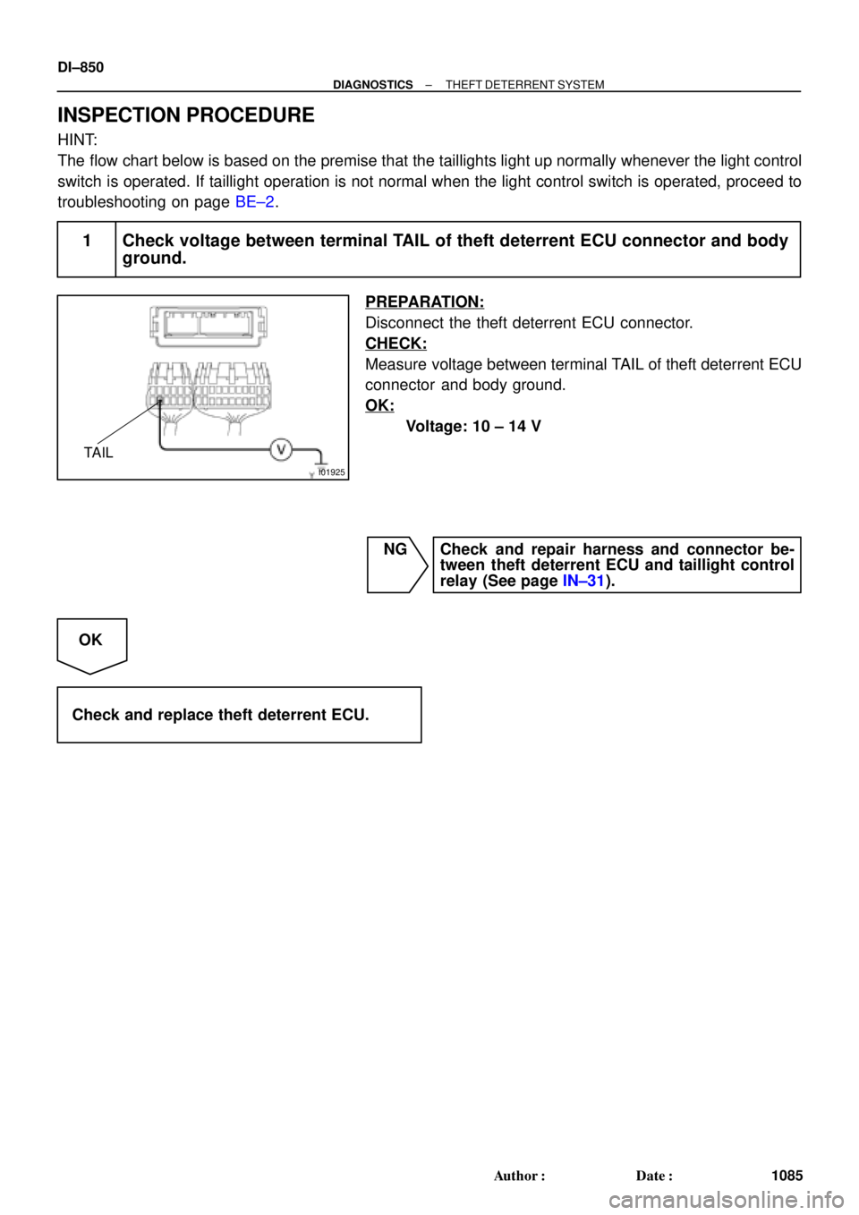
1 Check voltage between terminal TAIL of theft deterrent ECU connector and body
ground.
PREPARATION:
Disconnect the theft deterrent ECU connector.
CHECK:
Measure voltage between terminal TAIL of theft deterrent ECU
connector and body ground.
OK:
Voltage: 10 ± 14 V
NG Check and repair harness and connector be-
tween theft deterrent ECU and taillight control
relay (See page IN±31).
OK
Check and replace theft deterrent ECU.