Page 1526 of 4592
DI±314
± DIAGNOSTICSENGINE (1MZ±FE)
549 Author�: Date�:
5 Check filler neck for damage.
PREPARATION:
Remove the fuel tank cap.
CHECK:
Visually inspect the filler neck for damage.
NG Replace filler pipe.
OK
6 Check vacuum hoses between vapor pressure sensor and VSV for vapor
pressure sensor, and VSV for vapor pressure sensor and charcoal canister
(See page EC±3 , SF±62 and EC±6).
CHECK:
(a) Check that the vacuum hose is connected correctly.
(b) Check the vacuum hose for looseness and disconnection.
(c) Check the vacuum hose for cracks, hole and damage.
NG Repair or replace.
OK
7 Check hose and tube between fuel tank and charcoal canister.
CHECK:
(a) Check for proper connection of the fuel tank and fuel evap pipe (See page SF±1), fuel evap pipe and
fuel tube under the floor, fuel tube under the floor and charcoal canister.
(b) Check the hose and tube for cracks, hole and damage.
NG Repair or replace.
OK
Page 1529 of 4592
± DIAGNOSTICSENGINE (1MZ±FE)
DI±317
552 Author�: Date�:
12 Check fuell tank and fuel tank over fill check valve for cracks and damage.
(See page EC±2)
NG Replace fuel tank or fuel tank over fill check
valve.
OK
It is likely that vehicle user did not properly close fuel tank cap.
Please explain to customer how to properly install fuel tank cap.
Page 1537 of 4592

A07147
E2 (±) PTNK (+)
EngineStart
Stop
OFF ON OFF VSV for
ON
Vapor
Pressure
Sensor
VSV for
EVAP
5 sec.
Measure Voltage
± DIAGNOSTICSENGINE (1MZ±FE)
DI±325
560 Author�: Date�:
14 Check vacuum hoses between charcoal canister and VSV for vapor pressure
sensor, and vapor pressure sensor and VSV for vapor pressure sensor.
CHECK:
(a) Check that the vacuum hose is connected correctly.
(b) Check the vacuum hose for looseness and disconnection.
(c) Check the vacuum hose for cracks, hole, damage and blockage.
NG Repair or replace.
OK
15 Check charcoal canister.
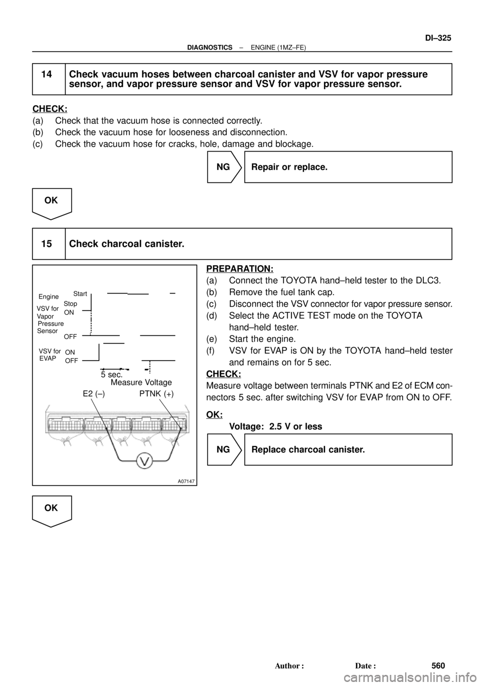
PREPARATION:
(a) Connect the TOYOTA hand±held tester to the DLC3.
(b) Remove the fuel tank cap.
(c) Disconnect the VSV connector for vapor pressure sensor.
(d) Select the ACTIVE TEST mode on the TOYOTA
hand±held tester.
(e) Start the engine.
(f) VSV for EVAP is ON by the TOYOTA hand±held tester
and remains on for 5 sec.
CHECK:
Measure voltage between terminals PTNK and E2 of ECM con-
nectors 5 sec. after switching VSV for EVAP from ON to OFF.
OK:
Voltage: 2.5 V or less
NG Replace charcoal canister.
OK
Page 2177 of 4592

A09428
(Fig.1)
Acceptable
Resistance kW
± 20 0 20 40 60 80 100
(± 4) (32) (68) (104) (140) (176) (212) 30
20
10
5
3
2
1
0.5
0.3
0.2
0.1
Te m p .°C (F°)
DI±26
± DIAGNOSTICSENGINE
DTC P0110 Intake Air Temp. Circuit Malfunction
CIRCUIT DESCRIPTION
The intake air temperature sensor is built into the air cleaner
cap and senses the intake air temperature.
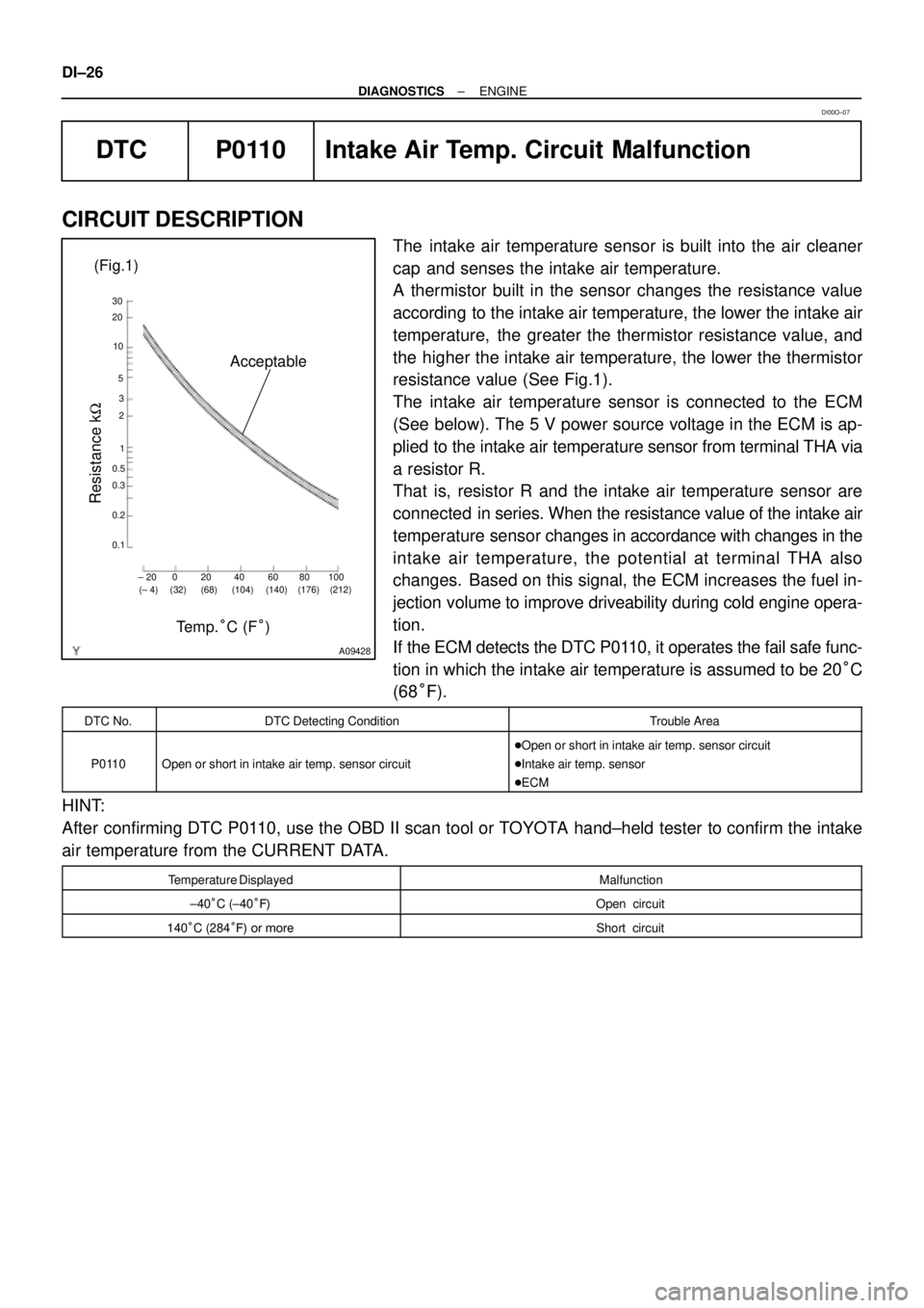
A thermistor built in the sensor changes the resistance value
according to the intake air temperature, the lower the intake air
temperature, the greater the thermistor resistance value, and
the higher the intake air temperature, the lower the thermistor
resistance value (See Fig.1).
The intake air temperature sensor is connected to the ECM
(See below). The 5 V power source voltage in the ECM is ap-
plied to the intake air temperature sensor from terminal THA via
a resistor R.
That is, resistor R and the intake air temperature sensor are
connected in series. When the resistance value of the intake air
temperature sensor changes in accordance with changes in the
intake air temperature, the potential at terminal THA also
changes. Based on this signal, the ECM increases the fuel in-
jection volume to improve driveability during cold engine opera-
tion.
If the ECM detects the DTC P0110, it operates the fail safe func-
tion in which the intake air temperature is assumed to be 20°C
(68°F).
DTC No.DTC Detecting ConditionTrouble Area
P0110Open or short in intake air temp. sensor circuit
�Open or short in intake air temp. sensor circuit
�Intake air temp. sensor
�ECM
HINT:
After confirming DTC P0110, use the OBD II scan tool or TOYOTA hand±held tester to confirm the intake
air temperature from the CURRENT DATA.
Temperature DisplayedMalfunction
±40°C (±40°F)Open circuit
140°C (284°F) or moreShort circuit
DI00O±07
Page 2518 of 4592
EC03A±03
B06542
PCV Valve
VSV for EGR
Front TWC
(California)EGR Vacuum Modulator
EGR Valve
TWC (Except California)
Rear TWC (California)
VSV for EVAP
Vent Line
Charcoal Canister
Fuel Tank
EVAP Line
Air Drain Hose
Filler Pipe
Air Inlet LinePurge Line Cutoff Valve
Fill Check Valve
EVAP Service Port
Fuel Tank Cap
VSV for Vapor
Pressure Sensor Vapor Pressure Sensor
EC±2
± EMISSION CONTROL (5S±FE)PARTS LAYOUT AND SCHEMATIC DRAWING
1400 Author�: Date�:
PARTS LAYOUT AND SCHEMATIC DRAWING
LOCATION
Page 2519 of 4592
EC03B±03
B06549
VSV for EGR Front TWC
(California)EGR Vacuum Modulator
EGR
Valve
TWC (Except California)
Rear TWC (California)VSV
for EVAP
Vent Line
Charcoal CanisterFuel Tank EVAP Line
Air Drain HoseFiller Pipe
Air Inlet Line Purge LineEVAP Service Port
Fuel Tank Cap
Vapor
Pressure
SensorVSV for Vapor
Pressure Sensor
± EMISSION CONTROL (5S±FE)PARTS LAYOUT AND SCHEMATIC DRAWING
EC±3
1401 Author�: Date�:
DRAWING
Page 2522 of 4592

EC03E±05
B01082B04812B06707
Type A
Type BGasket
Gasket
B06544
Vacuum
Gauge
S05331
EC±6
± EMISSION CONTROL (5S±FE)EVAPORATIVE EMISSION (EVAP) CONTROL SYSTEM
1404 Author�: Date�:
INSPECTION
1. INSPECT LINES AND CONNECTORS
Visually check for loose connections, sharp bends or damage.
2. INSPECT FUEL TANK FILLER PIPE
Visually check for deformation, cracks or fuel leakage.
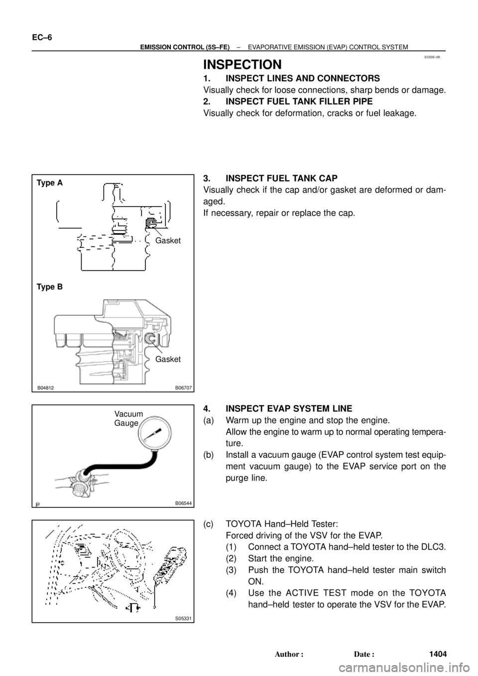
3. INSPECT FUEL TANK CAP
Visually check if the cap and/or gasket are deformed or dam-
aged.
If necessary, repair or replace the cap.
4. INSPECT EVAP SYSTEM LINE
(a) Warm up the engine and stop the engine.
Allow the engine to warm up to normal operating tempera-
ture.
(b) Install a vacuum gauge (EVAP control system test equip-
ment vacuum gauge) to the EVAP service port on the
purge line.
(c) TOYOTA Hand±Held Tester:
Forced driving of the VSV for the EVAP.
(1) Connect a TOYOTA hand±held tester to the DLC3.
(2) Start the engine.
(3) Push the TOYOTA hand±held tester main switch
ON.
(4) Use the ACTIVE TEST mode on the TOYOTA
hand±held tester to operate the VSV for the EVAP.
Page 2524 of 4592

B06546
Pressure
Gauge
Pressure
B06547
Fuel Tank Cap
B01250
Air
Disconnect
EVAP Line Hose
B01251
Air
Disconnect
Cap
Disconnect
EVAP Line Hose
Purge Line Hose
Purge Port
EC±8
± EMISSION CONTROL (5S±FE)EVAPORATIVE EMISSION (EVAP) CONTROL SYSTEM
1406 Author�: Date�:
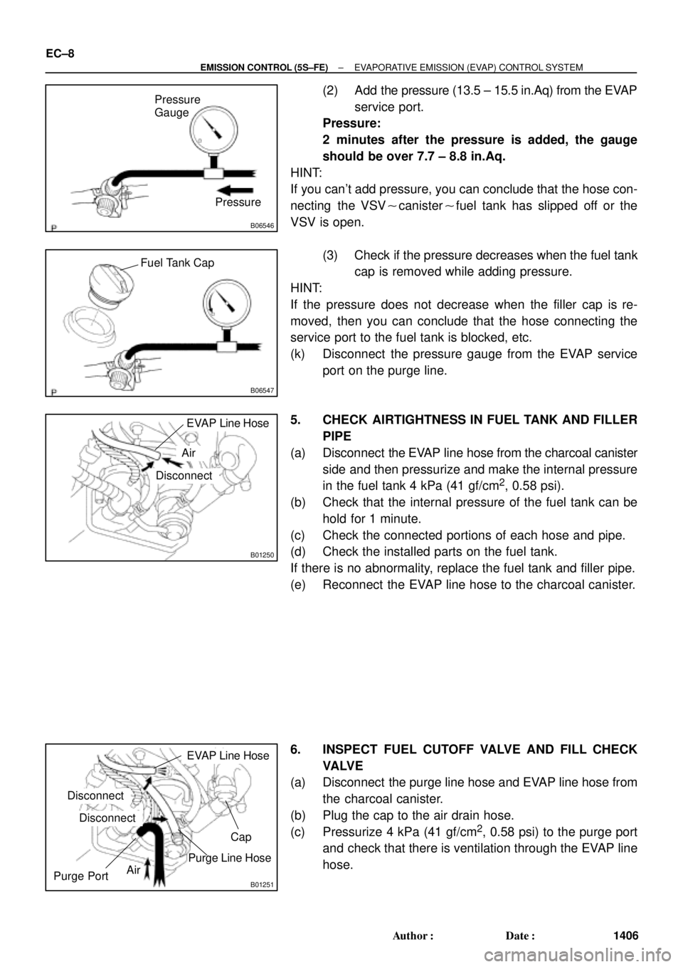
(2) Add the pressure (13.5 ± 15.5 in.Aq) from the EVAP
service port.
Pressure:
2 minutes after the pressure is added, the gauge
should be over 7.7 ± 8.8 in.Aq.
HINT:
If you can't add pressure, you can conclude that the hose con-
necting the VSV�canister�fuel tank has slipped off or the
VSV is open.
(3) Check if the pressure decreases when the fuel tank
cap is removed while adding pressure.
HINT:
If the pressure does not decrease when the filler cap is re-
moved, then you can conclude that the hose connecting the
service port to the fuel tank is blocked, etc.
(k) Disconnect the pressure gauge from the EVAP service
port on the purge line.
5. CHECK AIRTIGHTNESS IN FUEL TANK AND FILLER
PIPE
(a) Disconnect the EVAP line hose from the charcoal canister
side and then pressurize and make the internal pressure
in the fuel tank 4 kPa (41 gf/cm
2, 0.58 psi).
(b) Check that the internal pressure of the fuel tank can be
hold for 1 minute.
(c) Check the connected portions of each hose and pipe.
(d) Check the installed parts on the fuel tank.
If there is no abnormality, replace the fuel tank and filler pipe.
(e) Reconnect the EVAP line hose to the charcoal canister.
6. INSPECT FUEL CUTOFF VALVE AND FILL CHECK
VA LV E
(a) Disconnect the purge line hose and EVAP line hose from
the charcoal canister.
(b) Plug the cap to the air drain hose.
(c) Pressurize 4 kPa (41 gf/cm
2, 0.58 psi) to the purge port
and check that there is ventilation through the EVAP line
hose.