Page 839 of 4592
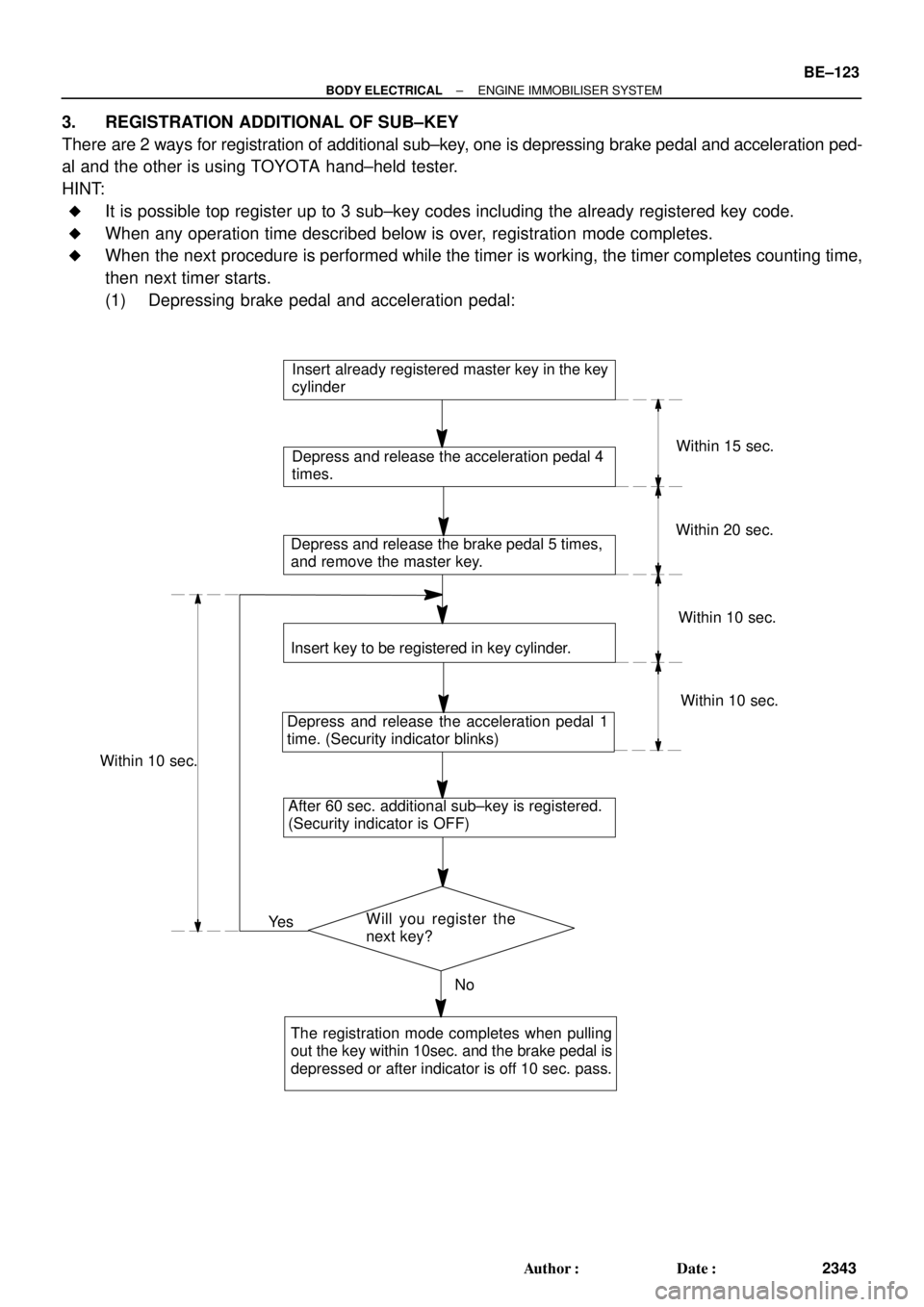
Will you register the
next key?
No Ye s
Insert already registered master key in the key
cylinder
Depress and release the acceleration pedal 4
times.
Depress and release the brake pedal 5 times,
and remove the master key.
Insert key to be registered in key cylinder.
Depress and release the acceleration pedal 1
time. (Security indicator blinks)
The registration mode completes when pulling
out the key within 10sec. and the brake pedal is
depressed or after indicator is off 10 sec. pass. Within 10 sec.Within 15 sec.
Within 20 sec.
Within 10 sec.
Within 10 sec.
After 60 sec. additional sub±key is registered.
(Security indicator is OFF)
± BODY ELECTRICALENGINE IMMOBILISER SYSTEM
BE±123
2343 Author�: Date�:
3. REGISTRATION ADDITIONAL OF SUB±KEY
There are 2 ways for registration of additional sub±key, one is depressing brake pedal and acceleration ped-
al and the other is using TOYOTA hand±held tester.
HINT:
�It is possible top register up to 3 sub±key codes including the already registered key code.
�When any operation time described below is over, registration mode completes.
�When the next procedure is performed while the timer is working, the timer completes counting time,
then next timer starts.
(1) Depressing brake pedal and acceleration pedal:
Page 841 of 4592
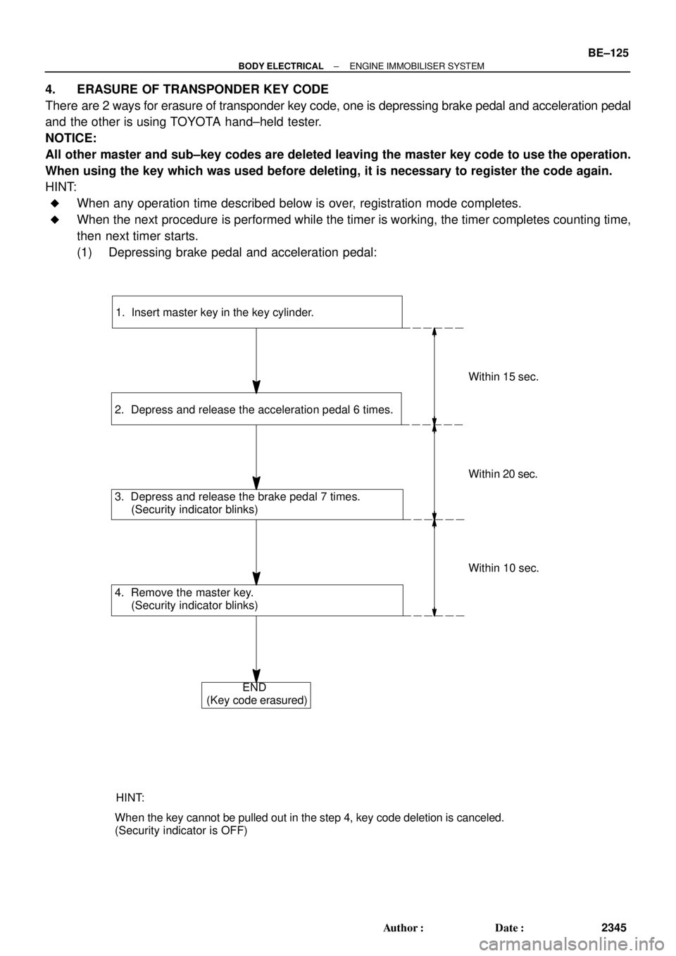
1. Insert master key in the key cylinder.
2. Depress and release the acceleration pedal 6 times.
3. Depress and release the brake pedal 7 times.
(Security indicator blinks)
4. Remove the master key.
(Security indicator blinks)
HINT:
When the key cannot be pulled out in the step 4, key code deletion is canceled.
(Security indicator is OFF) END
(Key code erasured)
Within 15 sec.
Within 20 sec.
Within 10 sec.
± BODY ELECTRICALENGINE IMMOBILISER SYSTEM
BE±125
2345 Author�: Date�:
4. ERASURE OF TRANSPONDER KEY CODE
There are 2 ways for erasure of transponder key code, one is depressing brake pedal and acceleration pedal
and the other is using TOYOTA hand±held tester.
NOTICE:
All other master and sub±key codes are deleted leaving the master key code to use the operation.
When using the key which was used before deleting, it is necessary to register the code again.
HINT:
�When any operation time described below is over, registration mode completes.
�When the next procedure is performed while the timer is working, the timer completes counting time,
then next timer starts.
(1) Depressing brake pedal and acceleration pedal:
Page 842 of 4592
1. Insert master key in the key cylinder.
2. Require key code deletion from hand±held tester.
(Security indicator blinks)
3. Remove the master key.
HINT:
When the key cannot be pulled out in the step 3, key code deletion is canceled.
(Security indicator is OFF) END
(Key code erasured)
Within 120 sec.
Within 10 sec.
BE±126
± BODY ELECTRICALENGINE IMMOBILISER SYSTEM
2346 Author�: Date�:
(2) Using TOYOTA hand±held tester:
Page 918 of 4592
H01983
Code Shape Size
Code Shape Size
Code Shape Size
A
D
G
J
M
PBC
EF
HI
K
NL
O L = 16 (0.63) ù = 5.2 (0.21)mm (in.)
L = 16 (0.63) ù = 6.0 (0.24)
L = 20 (0.79) ù = 6.0 (0.24)
L = 20 (0.79) ù = 6.0 (0.24)
L = 10 (0.39) ù = 5.0 (0.20)
L = 20 (0.79) ù = 5.2 (0.21)
L = 22 (0.87) ù = 8.0 (0.31)
L = 20 (0.79) ù = 6.0 (0.24)
L = 20 (0.79) ù = 6.0 (0.24)
L = 18 (0.79) ù = 6.0 (0.24)
L = 14 (0.55) ù = 5.0 (0.20)
L = 12 (0.47) ù = 5.0 (0.20)
L = 18 (0.17) ù = 8.0 (0.31)8 x 1.256 x 1.00
6 x 1.00 BO±74
± BODYINSTRUMENT PANEL
2422 Author�: Date�:
HINT:
Screw shapes and size are indicated in the table below. The code (ºAº±ºPº) correspond to those indicated
on the previous page.
Page 971 of 4592
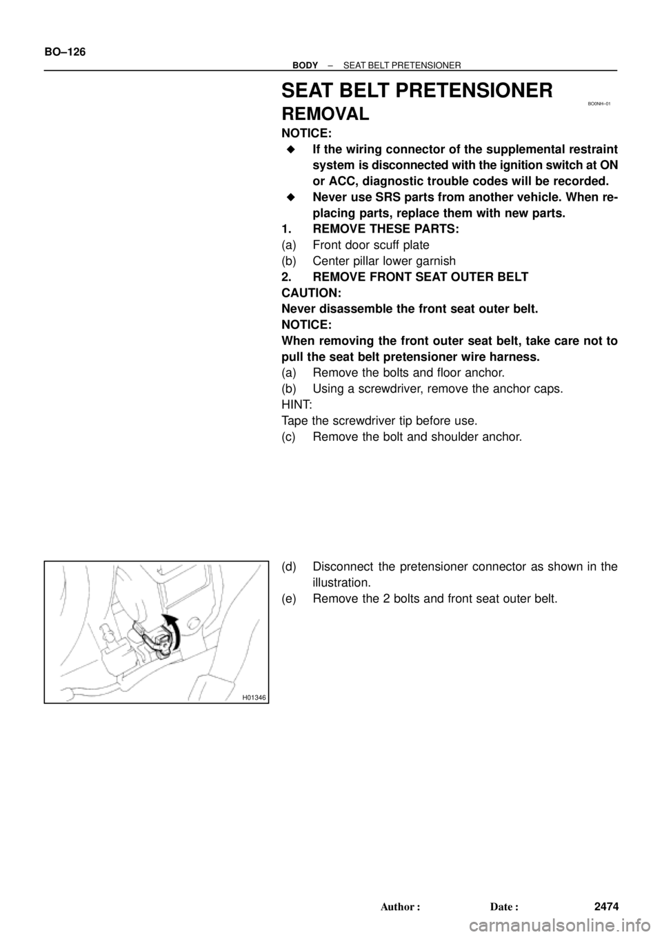
BO0NH±01
H01346
BO±126
± BODYSEAT BELT PRETENSIONER
2474 Author�: Date�:
SEAT BELT PRETENSIONER
REMOVAL
NOTICE:
�If the wiring connector of the supplemental restraint
system is disconnected with the ignition switch at ON
or ACC, diagnostic trouble codes will be recorded.
�Never use SRS parts from another vehicle. When re-
placing parts, replace them with new parts.
1. REMOVE THESE PARTS:
(a) Front door scuff plate
(b) Center pillar lower garnish
2. REMOVE FRONT SEAT OUTER BELT
CAUTION:
Never disassemble the front seat outer belt.
NOTICE:
When removing the front outer seat belt, take care not to
pull the seat belt pretensioner wire harness.
(a) Remove the bolts and floor anchor.
(b) Using a screwdriver, remove the anchor caps.
HINT:
Tape the screwdriver tip before use.
(c) Remove the bolt and shoulder anchor.
(d) Disconnect the pretensioner connector as shown in the
illustration.
(e) Remove the 2 bolts and front seat outer belt.
Page 1213 of 4592

DI00F±08
Vehicle Brought to Workshop
Customer Problem Analysis P. DI±2
Problem Symptom Confirmation
If the engine does not start perform steps 10 and 12 firstConnect the OBD II scan tool or TOYOTA hand±held tester to DLC3 P. DI±3
If the display indicates a communication fault in the tool, inspect DLC3 P. DI±3
Check DTC and Freezed Frame Data (Precheck)
Record or Print DTC and Freezed Frame Data P. DI±3
Clear DTC and Freezed Frame Data P. DI±3
Visual Inspection
Setting the Check Mode Diagnosis P. DI±3
Symptom Simulation P. IN±21
Basic Inspection P. DI±3DTC Chart P. DI±16
Problem Symptoms Table P. DI±28
Circuit Inspection P. DI±29
Adjustment, Repair
DTC Check P. DI±3
Titles insideare titles of pages in
in the bottom portion. See the indicated
pages for detailed explanations.this manual with the page number indicated
Malfunction
occurs.Malfunction does not occur.
Parts Inspection
Check for Intermittent Problems P. DI±3
Identification of Problem
Confirmation Test
End 1
2
3
4
5
6
7
108
9
11
12
13
15 14
16
Normal Malfunction code.
17
± DIAGNOSTICSENGINE (5S±FE)
DI±1
236 Author�: Date�:
ENGINE (5S±FE)
HOW TO PROCEED WITH TROUBLESHOOTING
Troubleshoot in accordance with the procedure on the following page.
Page 1214 of 4592
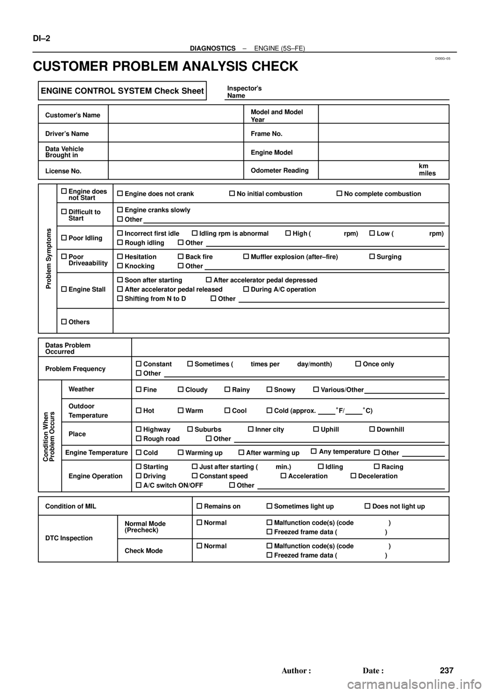
DI00G±05
ENGINE CONTROL SYSTEM Check Sheet
Customer's Name
Driver's Name
Data Vehicle
Brought in
License No.
Model and Model
Year
Frame No.
Engine Model
Odometer Reading
Problem Symptoms
Engine does
not Start
Difficult to
Start
Poor Idling
Poor
Driveaability
Engine Stall
Others
Engine does not crankNo initial combustionNo complete combustion
Engine cranks slowly
Other
Incorrect first idleIdling rpm is abnormalHigh ( rpm)Low ( rpm)
Rough idling
Other
HesitationBack fireMuffler explosion (after±fire)Surging
Knocking
Other
Soon after startingAfter accelerator pedal depressed
After accelerator pedal released
During A/C operation
Shifting from N to D
Other
Datas Problem
Occurred
Problem Frequency
Condition When
Problem Occurs
Weather
Engine Operation
Engine Temperature Place Outdoor
TemperatureConstant
Sometimes ( times per day/month)Once only
Other
Fine
CloudyRainySnowyVarious/Other
Hot
Warm CoolCold (approx. °F/ °C)
Highway
SuburbsInner cityUphillDownhill
Rough road
Other
Cold
Warming upAfter warming upAny temperatureOther
Starting
Just after starting ( min.)IdlingRacing
Driving
Constant speedAccelerationDeceleration
A/C switch ON/OFF
Other
Condition of MILRemains on Sometimes light up Does not light up
NormalMalfunction code(s) (code )
Freezed frame data ( )
NormalMalfunction code(s) (code )
Freezed frame data ( )
Normal Mode
(Precheck)
Check Mode DTC InspectionInspector's
Name
km
miles
DI±2
± DIAGNOSTICSENGINE (5S±FE)
237 Author�: Date�:
CUSTOMER PROBLEM ANALYSIS CHECK
Page 1215 of 4592

DI00H±08
FI0534
S05331
TOYOTA Hand±Held Tester
DLC3
± DIAGNOSTICSENGINE (5S±FE)
DI±3
238 Author�: Date�:
PRE±CHECK
1. DIAGNOSIS SYSTEM
(a) Description
�When troubleshooting OBD II vehicles, the only dif-
ference from the usual troubleshooting procedure
is that you connect to the vehicle the OBD II scan
tool complying with SAE J1978 or TOYOTA hand±
held tester, and read off various data output from
the vehicle's ECM.
�OBD II regulations require that the vehicle's on±
board computer lights up the Malfunction Indicator
Lamp (MIL) on the instrument panel when the com-
puter detects a malfunction in the emission control
system / components or in the powertrain control
components which affect vehicle emissions, or a
malfunction in the computer. In addition to the MIL
lighting up when a malfunction is detected, the ap-
plicable Diagnostic Trouble Code (DTC) prescribed
by SAE J2012 are recorded in the ECM memory.
(See page DI±16)
If the malfunction does not reoccur in 3 consecutive trips, the
MIL goes off automarially but the DTCs remain recorded in the
ECM memory.
�To check the DTCs, connect the OBD II scan tool or
TOYOTA hand±held tester to Data Link Connector
3 (DLC3) on the vehicle. The OBD II scan tool or
TOYOTA hand±held tester also enables you to
erase the DTCs and check freezed frame data and
various forms of engine data (For operating instruc-
tions, see the OBD II scan tool's instruction book.)
DTCs include SAE controlled codes and manufac-
turer controlled codes. SAE controlled codes must
be set as prescribed by the SAE, while manufactur-
er controlled codes can be set freely by the
manufacturer within the prescribed limits. (See DTC
chart on page DI±16)