Page 1557 of 4592

DI±345
580 Author�: Date�:
DTC P1133 A/F Sensor Circuit Response Malfunction
(Bank 1 Sensor 1) (Only for California Spec.)
DTC P1153 A/F Sensor Circuit Response Malfunc")
± DIAGNOSTICSENGINE (1MZ±FE)
DI±345
580 Author�: Date�:
DTC P1133 A/F Sensor Circuit Response Malfunction
(Bank 1 Sensor 1) (Only for California Spec.)
DTC P1153 A/F Sensor Circuit Response Malfunction
(Bank 2 Sensor 1) (Only for California Spec.)
CIRCUIT DESCRIPTION
Refer to DTC P0125 (Insufficient Coolant Temp. for Closed Loop Fuel Control (Only for California Spec.))
on page DI±249.
DTC No.DTC Detecting ConditionTrouble Area
P1133
P1155
After engine is warmed up and during vehicle driving at
engine speed 1,400 rpm or more and vehicle speed 60
km/h (38 mph) or more, if response characteristic of A/F
sensor becomes deteriorated
(2 trip detection logic)
�A/F sensors (bank 1, 2 sensor 1)
INSPECTION PROCEDURE
HINT:
Read freeze frame data using TOYOTA hand±held tester or OBD II scan tool. Because freeze frame records
the engine conditions when the malfunction is detected, when troubleshooting it is useful for determining
whether the vehicle was running or stopped, the engine warmed up or not, the air±fuel ratio lean or rich, etc.
at the time of the malfunction.
1 Are there any other codes (besides DTC P1133, P1153) being output?
YES Go to relevant DTC chart.
NO
DI1K7±03
Page 1570 of 4592
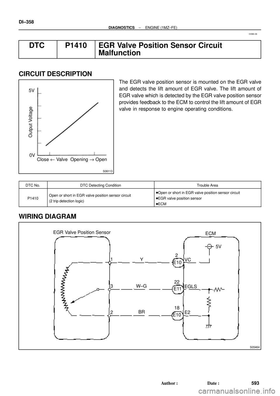
S06113
Close u Valve Opening " Open 0V 5V
Output Voltage
S05464
EGR Valve Position Sensor
3ECM
1
2Y
W±G
BRVC5V
EGLS
E2 E102
E1122
E1018 DI±358
± DIAGNOSTICSENGINE (1MZ±FE)
593 Author�: Date�:
DTC P1410 EGR Valve Position Sensor Circuit
Malfunction
CIRCUIT DESCRIPTION
The EGR valve position sensor is mounted on the EGR valve
and detects the lift amount of EGR valve. The lift amount of
EGR valve which is detected by the EGR valve position sensor
provides feedback to the ECM to control the lift amount of EGR
valve in response to engine operating conditions.
DTC No.DTC Detecting ConditionTrouble Area
P1410Open or short in EGR valve position sensor circuit
(2 trip detection logic)�Open or short in EGR valve position sensor circuit
�EGR valve position sensor
�ECM
WIRING DIAGRAM
DI086±06
Page 1592 of 4592
A00306
135
24 6 IACVIACV closed (VSV: ON)
Throttle Valve30°
3,700 rpm
Engine speed
Throttle valve
opening angle
FI7011 FI6570
A07452
From Battery 2J2
W±B
B±Y
J20
Junction
Connector 9
AAECMACIS
12
MRELB±W
VSV for ACIS
R±Y B±Y 17
2K
2A 2F
51 2
3 4Engine Room J/B
EFI
EBJunction
Connector BB+
B±Y178
E11E7
B
B±YE01
B±W
J36 J35CC
EFI Relay
J27 J28
II3Junction Connector DI±380
± DIAGNOSTICSENGINE (1MZ±FE)
615 Author�: Date�:
IACV Control VSV Circuit
CIRCUIT DESCRIPTION
This circuit opens and closes the IACV (Intake Air Control Valve) in response to the engine load in order to
increase the intake efficiency (ACIS: Acoustic Control Induction System).
When the engine speed is 3,700 rpm or less and the throttle valve opening angle is 60° or more, the ECM
turns the VSV ON and closes the IACV. At all other times, the VSV is OFF, so the IACV is open.
WIRING DIAGRAM
DI08E±06
Page 1612 of 4592
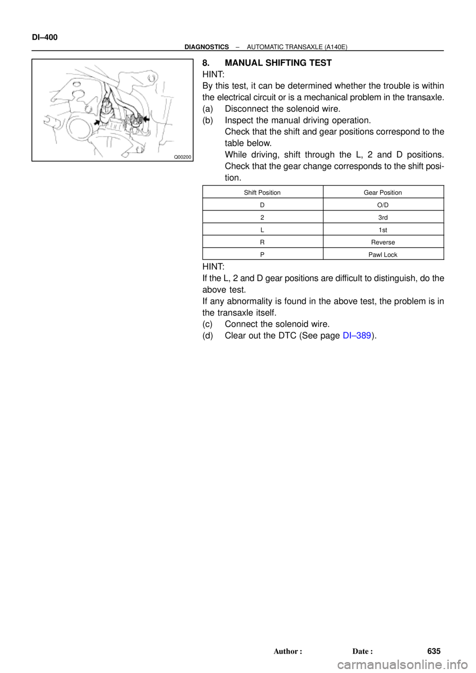
Q00200
DI±400
± DIAGNOSTICSAUTOMATIC TRANSAXLE (A140E)
635 Author�: Date�:
8. MANUAL SHIFTING TEST
HINT:
By this test, it can be determined whether the trouble is within
the electrical circuit or is a mechanical problem in the transaxle.
(a) Disconnect the solenoid wire.
(b) Inspect the manual driving operation.
Check that the shift and gear positions correspond to the
table below.
While driving, shift through the L, 2 and D positions.
Check that the gear change corresponds to the shift posi-
tion.
Shift PositionGear Position
DO/D
23rd
L1st
RReverse
PPawl Lock
HINT:
If the L, 2 and D gear positions are difficult to distinguish, do the
above test.
If any abnormality is found in the above test, the problem is in
the transaxle itself.
(c) Connect the solenoid wire.
(d) Clear out the DTC (See page DI±389).
Page 1660 of 4592
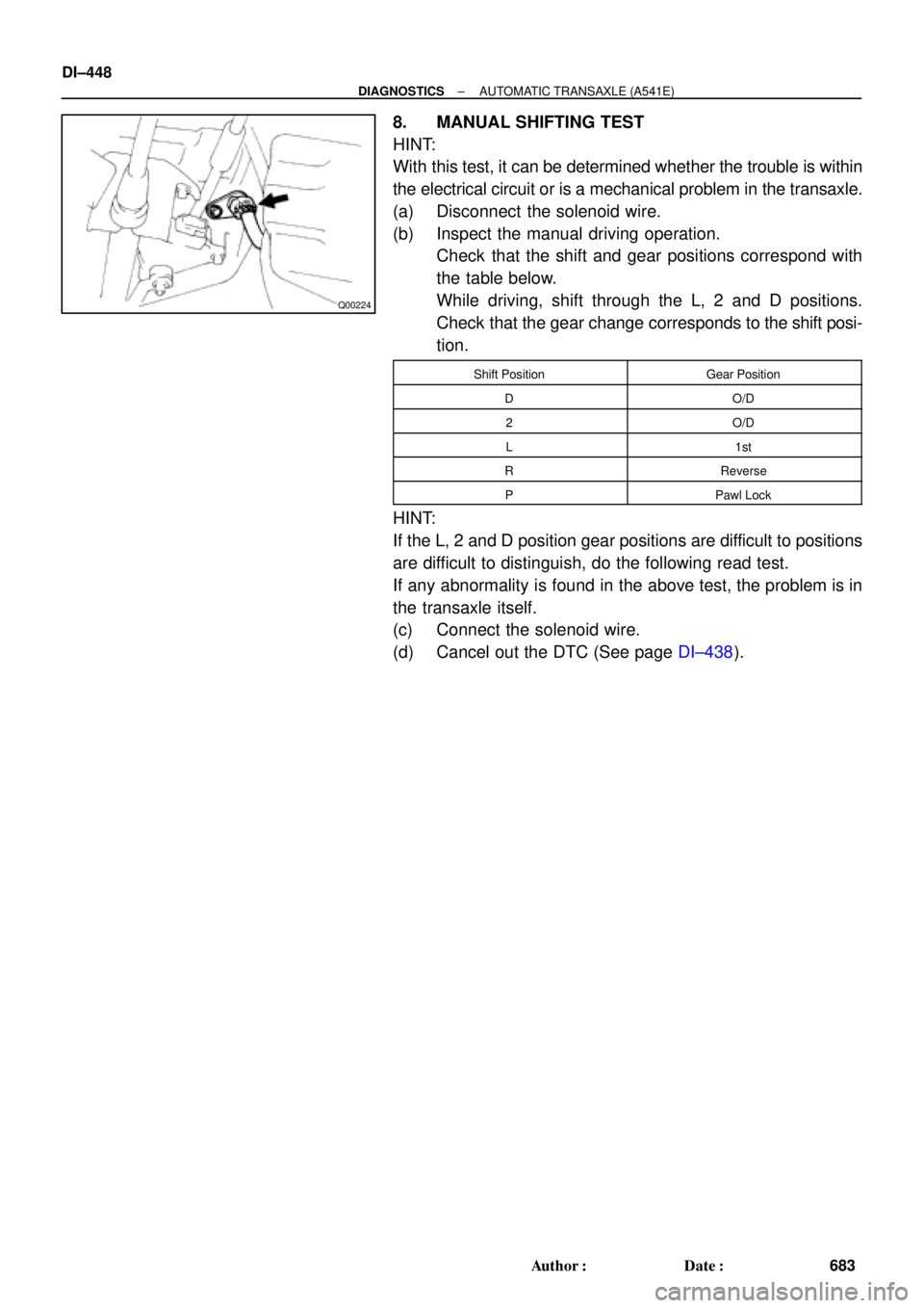
Q00224
DI±448
± DIAGNOSTICSAUTOMATIC TRANSAXLE (A541E)
683 Author�: Date�:
8. MANUAL SHIFTING TEST
HINT:
With this test, it can be determined whether the trouble is within
the electrical circuit or is a mechanical problem in the transaxle.
(a) Disconnect the solenoid wire.
(b) Inspect the manual driving operation.
Check that the shift and gear positions correspond with
the table below.
While driving, shift through the L, 2 and D positions.
Check that the gear change corresponds to the shift posi-
tion.
Shift PositionGear Position
DO/D
2O/D
L1st
RReverse
PPawl Lock
HINT:
If the L, 2 and D position gear positions are difficult to positions
are difficult to distinguish, do the following read test.
If any abnormality is found in the above test, the problem is in
the transaxle itself.
(c) Connect the solenoid wire.
(d) Cancel out the DTC (See page DI±438).
Page 1685 of 4592

Q04869
NC2 Revolution Sensor
D01094
Direct Clutch
Speed Sensor 2V3
1
V3
G R
E99
E94ECM
NC2
+
NC2±4 ~ 6 V
*1: Except California, w/ Engine Immobilizer and / or TRAC
*2: California, w/ Engine Immobilizer and / or TRAC*2 *1
E1114
26 *2 *1
E11
± DIAGNOSTICSAUTOMATIC TRANSAXLE (A541E)
DI±473
708 Author�: Date�:
DTC P1705 NC2 Revolution Sensor Circuit Malfunction
(Direct Clutch Speed Sensor)
CIRCUIT DESCRIPTION
This sensor detects the rotation speed of the direct clutch drum.
By comparing the direct clutch speed signal and the vehicle
speed sensor signal, the ECM detects the shift timing of the
gears and appropriately controls the engine torque and hydrau-
lic pressure in response to various conditions, thus performing
smooth gear shifting.
DTC No.DTC Detecting ConditionTrouble Area
P1705
The ECM detects conditions (a), (b), (c), (d), (e) and (f) conti-
nuity for 4 sec or more.
(2 trip detection logic)
(a) Vehicle speed : 32 km/h (20 mph) or more
(b) 3rd or 4th gear
(c) NC2 < 300 rpm
(d) Park/neutral position switch: OFF
(e) Solenoid valves and vehicle speed sensor are normal
(f) L position: OFF
�Open or short in direct clutch speed sensor circuit
�Direct clutch speed sensor
�ECM
WIRING DIAGRAM
DI02P±02
Page 1709 of 4592

DI±497
732 Author�: Date�:
DIAGNOSTIC TROUBLE CODE CHART
HINT:
�Using SST 09843 ±18020, connect the terminals Tc and E1, and remove the s")
DI03D±03
± DIAGNOSTICSANTI±LOCK BRAKE SYSTEM (DENSO Made)
DI±497
732 Author�: Date�:
DIAGNOSTIC TROUBLE CODE CHART
HINT:
�Using SST 09843 ±18020, connect the terminals Tc and E1, and remove the short pin.
�If any abnormality is not found when inspection parts, inspect the ECU.
�If a malfunction code is displayed during the DTC check, check the circuit listed for the code. For details
of each code, turn to the page referred to under the ºSee pageº for respective ºDTC No.º in the DTC
chart.
DTC No.
(See Page)Detection ItemTrouble Area
11
(DI±502)Open circuit in ABS solenoid relay circuit�ABS solenoid relay
12
(DI±502)Short circuit in ABS solenoid relay circuit
�ABS solenoid relay
�ABS solenoid relay circuit
13
(DI±507)Open circuit in ABS motor relay circuit�ABS motor relay
14
(DI±507)Short circuit in ABS motor relay circuit
�ABS motor relay
�ABS motor relay circuit
21
(DI±511)Open or short circuit in 2±position solenoid circuit for right front
wheel�ABS actuator
�SFRR or SFRH circuit
22
(DI±511)Open or short circuit in 2±position solenoid circuit for left front
wheel�ABS actuator
�SFLR or SFLH circuit
23
(DI±511)Open or short circuit in 2±position solenoid circuit for right rear
wheel�ABS actuator
�SRRR or SRRH circuit
24
(DI±511)Open or short circuit in 2±position solenoid circuit for left rear
wheel�ABS actuator
�SRLR or SRLH circuit
31
(DI±514)Right front wheel speed sensor signal malfunction
32
(DI±514)Left front wheel speed sensor signal malfunction�Right front, left front, right rear and left rear speed sensor
Eh d i it33
(DI±514)Right rear wheel speed sensor signal malfunction
�Each speed sensor circuit
�Speed sensor rotor
34
(DI±514)Left rear wheel speed sensor signal malfunction
33, 34
(DI±519)Rear speed sensor rotor faulty
�Rear axle hub
�Right rear, left rear speed sensor
�Rear speed sensor circuit
41
(DI±520)Power source voltage down
�Battery
�Charging system
�Power source circuit
49
(DI±523)Open circuit in stop light switch circuit�Stop light switch
�Stop light switch circuit
51
(DI±525)Pump motor is locked�ABS pump motor
Always ON
(DI±527)Malfunction in ECU�ECU
�Battery
Page 1754 of 4592

777 Author�: Date�:
DIAGNOSTIC TROUBLE CODE CHART
HINT:
�Using SST 09843 ±18020, connect the terminals Tc and E1.
�If a malfunctio")
DI03W±11
DI±542
± DIAGNOSTICSANTI±LOCK BRAKE SYSTEM (BOSCH Made)
777 Author�: Date�:
DIAGNOSTIC TROUBLE CODE CHART
HINT:
�Using SST 09843 ±18020, connect the terminals Tc and E1.
�If a malfunction code is displayed during the DTC check, check the circuit listed for the code. For details
of each code, turn to the page referred to under the ºSee pageº for respective ºDTC No.º in the DTC
chart.
DTC No.
(See Page)Detection ItemTrouble Area
11
(DI±546)ABS solenoid valve relay faulty
�ABS solenoid valve relay
�Valve supply voltage
�ECU
13
(DI±548)ABS pump motor faulty
�ABS motor relay
�Pump motor voltage
�Pump motor lead disconnected
�ECU
21
(DI±550)Right front solenoid valves faulty�ABS actuator (right front inlet or outlet solenoid valve)
22
(DI±550)Left front solenoid valves faulty�ABS actuator (left front inlet or outlet solenoid valve)
23
(DI±550)Right rear solenoid valves faulty�ABS actuator (right rear inlet or outlet solenoid valve)
24
(DI±550)Left rear solenoid valves faulty�ABS actuator (left rear inlet or outlet solenoid valve)
31
(DI±552)Right front wheel speed sensor signal malfunction
32
(DI±552)Left front wheel speed sensor signal malfunction�Right front, left front, right rear and left rear speed sensor
�Each speed sensor circuit
33
(DI±552)Right rear wheel speed sensor signal malfunction
�Each s eed sensor circuit
�Sensor installation
�ECU
34
(DI±552)Left rear wheel speed sensor signal malfunction
35
(DI±552)Open circuit in right front wheel speed sensor circuit�Right front, left front speed sensor
Eh d i it36
(DI±552)Open circuit in left front wheel speed sensor circuit
�Each speed sensor circuit
�ECU
37
(DI±557)Speed sensor rotor is wrong number of teeth on one of the 4
wheels�Speed sensor
�Sensor rotor
�ECU
38
(DI±552)Open circuit in right rear wheel speed sensor circuit�Right rear, left rear speed sensor
Eh d i it39
(DI±552)Open circuit in left rear wheel speed sensor circuit
�Each speed sensor circuit
�ECU
41
(DI±558)Low battery positive voltage
�Battery
�Charging system regulator
�Power source circuit
�ECU
58
(DI±561)Open circuit in stop light switch circuit
�Stop light switch
�Stop light switch circuit
�ECU
62
(DI±563)Malfunction in ECU�ECU

Throttle Valve30°
3,700 rpm
Engine speed
Throttle valve
opening angle
FI7011 FI6570
A07452
From Battery 2J2
W±B
B±Y
J20
Junction
Connector 9
AAECMACIS
12")