Page 3632 of 4592
SA07B±05
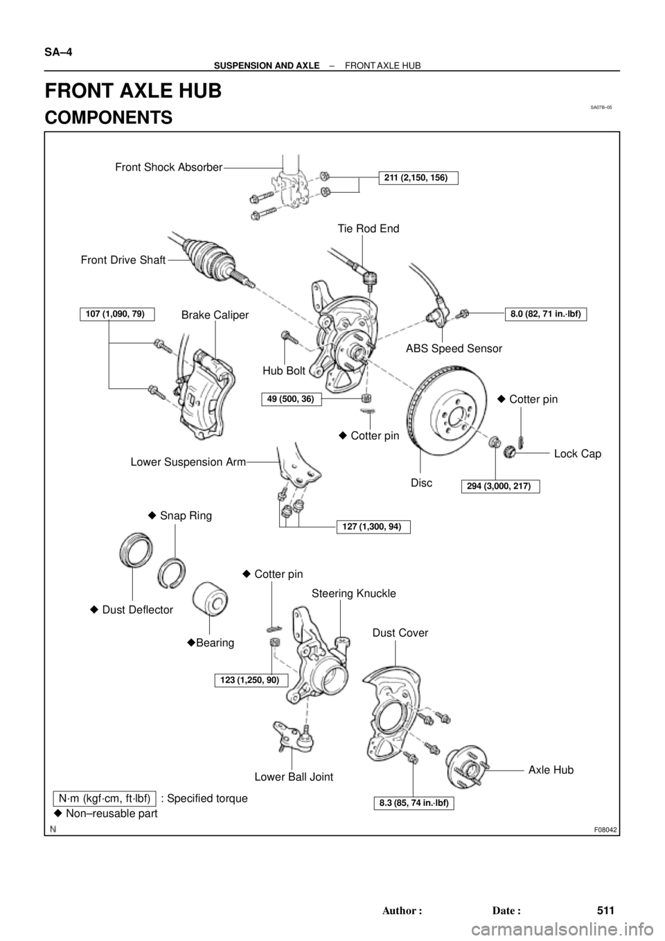
F08042
Front Shock Absorber
Tie Rod End
Front Drive Shaft
Brake Caliper
ABS Speed Sensor
Lower Suspension ArmLock Cap
� Snap Ring
� Dust DeflectorSteering Knuckle
Dust Cover
�Bearing
Lower Ball JointAxle Hub � Cotter pin� Cotter pin� Cotter pin Hub Bolt
Disc
N´m (kgf´cm, ft´lbf) : Specified torque
� Non±reusable part
127 (1,300, 94)
107 (1,090, 79)
49 (500, 36)
8.3 (85, 74 in.´lbf)
123 (1,250, 90)
211 (2,150, 156)
294 (3,000, 217)
8.0 (82, 71 in.´lbf)
SA±4
± SUSPENSION AND AXLEFRONT AXLE HUB
511 Author�: Date�:
FRONT AXLE HUB
COMPONENTS
Page 3634 of 4592

SA1JR±01
FA1535
SST
W03093
W03094
SST
W03095
SA±6
± SUSPENSION AND AXLEFRONT DRIVE SHAFT
REMOVAL
NOTICE:
�The hub bearing could be damaged if it is subjected
to the vehicle weight, such as when moving the ve-
hicle with the drive shaft removed.
Therefore, if it is absolutely necessary to place the ve-
hicle weight on the hub bearing, first support it with
SST.
SST 09608±16042 (09608±02021, 09608±02041)
�After disconnecting the drive shaft from the axle hub,
work carefully so as not to damage the ABS speed
sensor rotor serration on the drive shaft.
1. REMOVE FRONT WHEEL AND FRONT FENDER
APRON SEAL
2. DRAIN ATF
3. REMOVE DRIVE SHAFT LOCK NUT
(a) Remove the cotter pin and lock cap.
(b) While applying the brakes, remove the nut.
4. DISCONNECT TIE ROD END FROM STEERING
KNUCKLE
(a) Remove the cotter pin and nut.
(b) Using SST, disconnect the tie rod end from the steering
knuckle.
SST 09610±20012
5. DISCONNECT LOWER SUSPENSION ARM FROM
LOWER BALL JOINT
Remove the bolt and 2 nuts, and disconnect the lower suspen-
sion arm from the lower ball joint.
Page 3642 of 4592
 Install a new snap ring to the inboard joint shaft.
(b) Coat the gear oil")
SA1EC±02
SA±14
± SUSPENSION AND AXLEFRONT DRIVE SHAFT
INSTALLATION
1. LH drive shaft:
INSTALL DRIVE SHAFT TO TRANSAXLE
(a) Install a new snap ring to the inboard joint shaft.
(b) Coat the gear oil to the inboard joint shaft and differential case sliding surface.
(c) Set the snap ring with opening side facing downward.
(d) Using a brass bar and hammer, install the drive shaft.
NOTICE:
Be careful not to damage the dust cover of the drive shaft and oil seal lip of the transaxle.
HINT:
Whether the inboard joint shaft is in contact with the pinion shaft or not can be known from the sound or feel-
ing when driving it in.
(e) Check that there is 2 ± 3 mm (0.08 ± 0.12 in.) of play in the axial direction.
(f) Check that the drive shaft cannot be removed by hand.
2. RH drive shaft:
INSTALL DRIVE SHAFT TO TRANSAXLE
(a) Install the drive shaft.
NOTICE:
Be careful not to damage the dust cover of the drive shaft and oil seal lip of the transaxle.
(b) Using pliers, install a new snap ring.
(c) Install a new bearing lock bolt.
Torque: 32 N´m (330 kgf´cm, 24 ft´lbf)
3. CONNECT DRIVE SHAFT TO AXLE HUB
NOTICE:
Be careful not to damage the boot and ABS speed sensor rotor.
4. CONNECT LOWER SUSPENSION ARM TO LOWER BALL JOINT
Torque: 127 N´m (1,300 kgf´cm, 94 ft´lbf)
5. CONNECT TIE ROD END TO STEERING KNUCKLE
(a) Connect the tie rod end to the steering knuckle.
(b) Install the nut and a new cotter pin.
If the holes for the cotter pin are not aligned, tighten the nut further up to 60°.
Torque: 49 N´m (500 kgf´cm, 36 ft´lbf)
6. INSTALL DRIVE SHAFT LOCK NUT
(a) While applying brakes, install the nut.
Torque: 294 N´m (3,000 kgf´cm, 217 ft´lbf)
(b) Install the lock cap and a new cotter pin.
If the holes for the cotter pin are not aligned, tighten the nut further up to 60°.
7. FILL AND CHECK ATF (See page DI±133)
8. INSTALL FRONT FENDER APRON SEAL
9. INSTALL FRONT WHEEL
Torque: 103 N´m (1,050 kgf´cm, 76 ft´lbf)
10. CHECK FRONT WHEEL ALIGNMENT (See page SA±1)
11. CHECK ABS SPEED SENSOR SIGNAL (See page DI±177)
Page 3754 of 4592
BRAKE DISC ANTI±RUST COVER REMOVAL (CONT'D)Page 2 of 2
RECOMMENDED REMOVAL PROCEDURE:
Turn the right front wheel to full right lock.
Unhook the Anti±Rust Cover from the disc brake dust cover, then pull the center of the Anti±Rust
Cover toward the wheel. This separates the Anti±Rust Cover from the disc brake dust cover (see
illustration below).
Pull the center of the Anti±Rust Cover by hand towards you to break the thin portion of cover.
Remove the Anti±Rust Cover along the arch of the wheel disc by shaking it up and down. If the
cover is torn while removing, check to see that no parts of the cover are left inside.
Turn the steering wheel to full left lock and perform the same steps on the left front wheel. If
applicable, also remove the Anti±Rust Covers on the rear brakes.
Indicate on the new car inspection sheet that the Anti±Rust Covers have been removed.
Page 3756 of 4592
TOYOTA MOTOR SALES U.S.A., INC.
This TSB outlines the causes of brake vibration and pulsation, as well as the best corrective
measures to use.
CONTENTS
1) Symptoms of brake vibration and pulsation
2) Cause of vibration/pulsation problems
3) Advantages of using an on±car brake lathe
4) Rotor replacement and off±car brake lathe procedure
1) SYMPTOMS OF BRAKE VIBRATION AND PULSATION
Brake vibration problems generally involve one or both of two phenomena: body vibration and/
or pedal pulsation.
A. BRAKE VIBRATION
Applying brakes causes vibration to occur in the instrument panel, steering column, steering
wheel, and/or body of the vehicle (See Figure 1 below).
BRAKE VIBRATION AND/OR PULSATIONPage 1 of 6
BRAKES
BR94±002
FEBRUARY 7, 1994
ALL MODELS
Figure 1
Page 3757 of 4592
BR002±94
BRAKE VIBRATION AND/OR PULSATIONPage 2 of 6
B. PEDAL PULSATION
Applying brakes causes the brake pedal to pulsate. This brake pulsation sometimes
causes the steering wheel to oscillate when the brakes are applied (See Figure 2 below).
2) CAUSE OF VIBRATION/PULSATION PROBLEMS
Brake rotor thickness variation causes brake vibration due to changes in the braking force as
thick/thin portions of the rotor pass the pads. Brake rotor thickness variation can be measured
with a micrometer as shown in Figure 3 below.
Figure 2
10 mm
Divide Into
8 Equal Parts & Measure
at each location
Thickness Variation = Maximum ± Minimum
Figure 3
Page 3884 of 4592

WARRANTY PARTS MARKING PROCEDURE ± PG006-03September 26, 2003
Page 2 of 3
Dealers are requested to mark the location of the failure of all warranty parts that are
listed below.
This list is not inclusive. There may be other components that can be
marked in the area of failure. All other parts that can be marked should be marked.
assist grip assy headlamps
audio (blemish) headliner
back door garnish hoses
bumper covers instrument panel safety pad sub±assy
cargo cover (retractable) Interior light assemblies and covers
carpet knobs, levers, handles
clutch disc l/pulley pump assy
clutch flywheel mirrors (side and rearview)
combination meter glass navigation or VES screens
console and components pillar garnish
cowl assy rack and pinion/power steering gear assy
cowl side trim sub±assy radiator
cupholders room partition board
cylinder head cover sub±assy rotors (mark where min. runout is exceeded or warped)
dash panel insulator assy seat covers/cushions
dashboard and trim seat tracks
disc wheel soft trim
display panels spare tire cover
door handle assy steering column cover
door moulding steering wheel
door trim panel & molding tail lamps and covers
emblems transmission oil pan
engine oil pan visor
exhaust manifold washer jar
floor and cargo mats wheel cap
gear shift knob wheels
grills
Parts
Marking
Requirement
Parts
Marking
List
Page 3931 of 4592

Toyota Supports ASE CertificationPage 1 of 2
ST001-01Title:
STEERING WHEEL NUT SERVICE
SPECIFICATION
Models:
All Applicable Models
Technical Service
BULLETIN
February 16, 2001
To make the steering wheel installation procedure similar for all models, the steering
wheel nut tightening torque has been standardized.
MODELMODEL YEARS
TERCELEL42, 531991 ± 1998
ECHONCP122000
PASEOEL44, 541992 ± 1997
COROLLAAE10#, ZZE1101993 ± 2001
CELICAAT180, ST18#, AT2#,
ST2#, ZZT23#1990 ± 2000
MR2SW2#, ZZW301991 ± 1995; 2000
CAMRYSXV10, 20, MCV10, 201992 ± 2000
CAMRY CNGSXV232000 ± 2001
CAMRY SOLARASXV20, MCV201999 ± 2000
AVALONMCX10, 201995 ± 2000
SUPRAJZA801993 1/2 ± 1998
RAV4SXA1#1996 ± 2000
RAV4 EVBEA111998 ± 2000
PREVIATRC10, 201991 ± 1997
SIENNAMCL101998 ± 2000
HIGHLANDERACU20, 25, MCU20, 252001
4RUNNERRN12#, 13#, VZN12#, 13#,
18#, RZN180, 1851990 ± 2000
LAND CRUISERFZ80, FZJ80, UZJ1001991 ± 2000
TRUCKRN8#, 9#, 10#, 110,
VZN85, 9#, 10#, 1101989 ± 1995
TACOMARZN140, 150, 161, 171,
19#, VZN150, 160, 170, 1951995 1/2 ± 2000
T100VCK10, 201993 ± 1998
TUNDRAVCK30, 40, UCK30, 402000
OP CODEDESCRIPTIONTIMEOPNT1T2
N/ANot Applicable to Warranty ±±±±
STEERING
Introduction
Applicable
Vehicles
Warranty
Information
Page 2 of 2
RECOMMENDED REMOVAL PROCEDURE:
Turn the right front wheel to full right lock.
Unhook the Anti±Rust Cover from the disc brake dust cover, then p")
 Symptoms of brake vibration and pulsation
2)")
