Page 3568 of 4592
SA07D±01
R08859
SST
R00789
SST
W02110
SST
R11486
SST
SST
SA±12
± SUSPENSION AND AXLEFRONT AXLE HUB
1963 Author�: Date�:
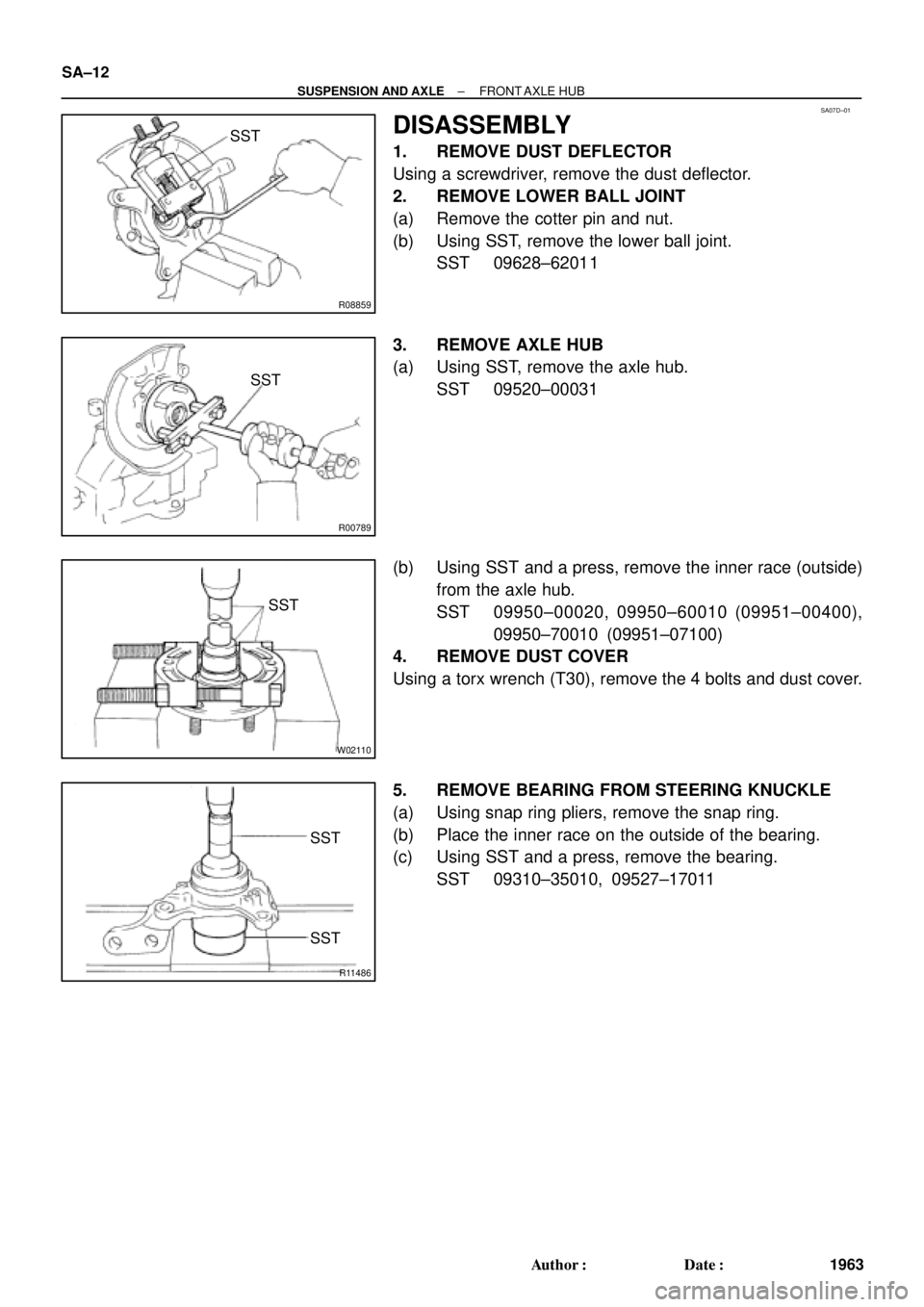
DISASSEMBLY
1. REMOVE DUST DEFLECTOR
Using a screwdriver, remove the dust deflector.
2. REMOVE LOWER BALL JOINT
(a) Remove the cotter pin and nut.
(b) Using SST, remove the lower ball joint.
SST 09628±62011
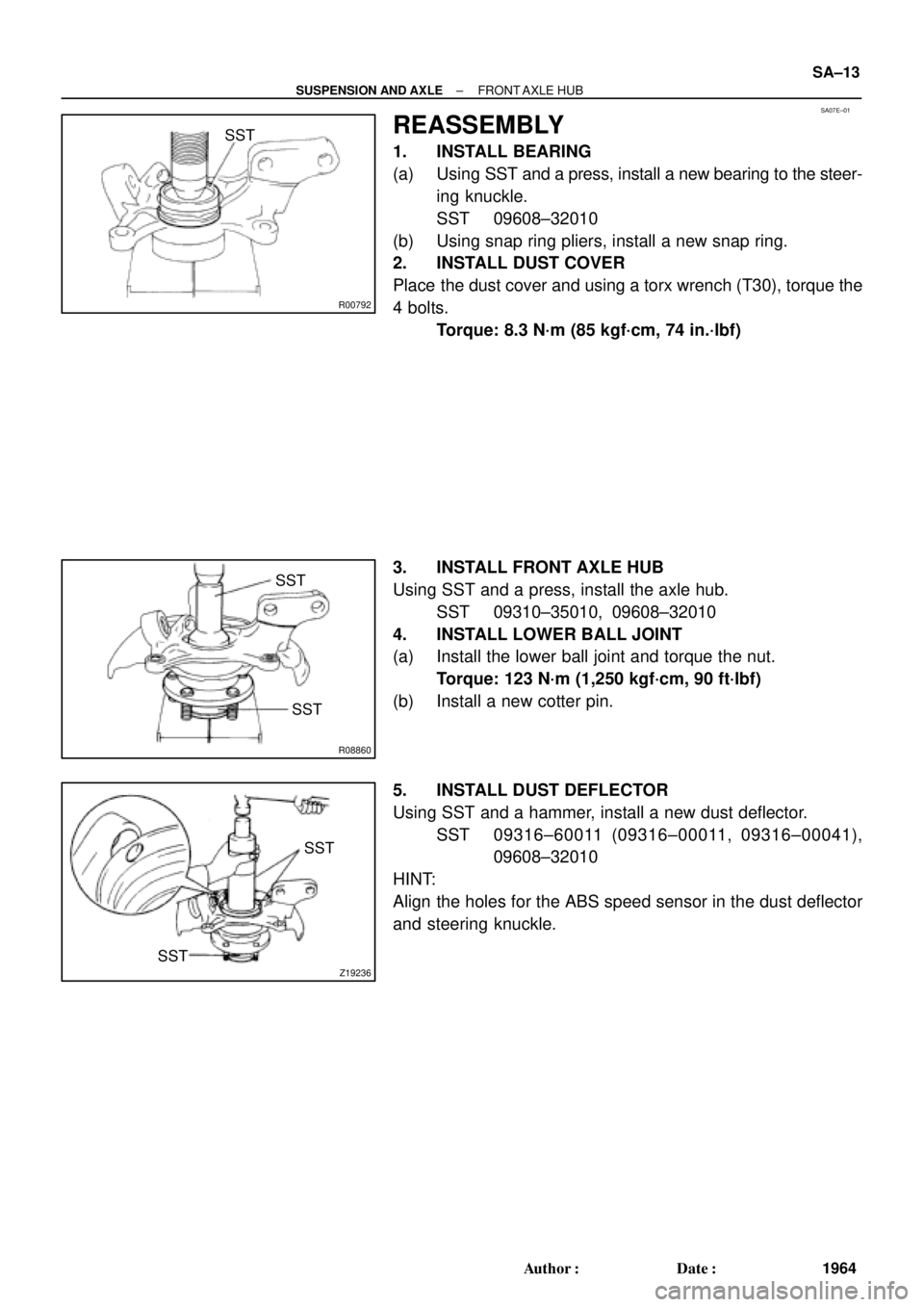
3. REMOVE AXLE HUB
(a) Using SST, remove the axle hub.
SST 09520±00031
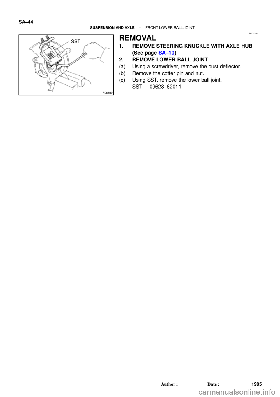
(b) Using SST and a press, remove the inner race (outside)
from the axle hub.
SST 09950±00020, 09950±60010 (09951±00400),
09950±70010 (09951±07100)
4. REMOVE DUST COVER
Using a torx wrench (T30), remove the 4 bolts and dust cover.
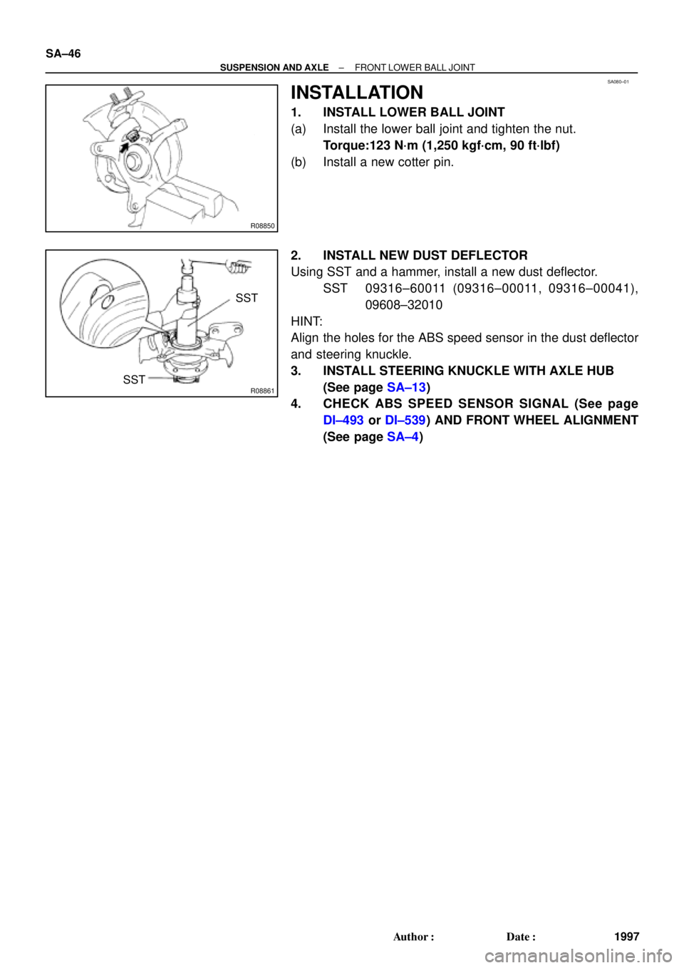
5. REMOVE BEARING FROM STEERING KNUCKLE
(a) Using snap ring pliers, remove the snap ring.
(b) Place the inner race on the outside of the bearing.
(c) Using SST and a press, remove the bearing.
SST 09310±35010, 09527±17011
Page 3569 of 4592
SA07E±01
R00792
SST
R08860
SST
SST
Z19236
SST
SST
± SUSPENSION AND AXLEFRONT AXLE HUB
SA±13
1964 Author�: Date�:
REASSEMBLY
1. INSTALL BEARING
(a) Using SST and a press, install a new bearing to the steer-
ing knuckle.
SST 09608±32010
(b) Using snap ring pliers, install a new snap ring.
2. INSTALL DUST COVER
Place the dust cover and using a torx wrench (T30), torque the
4 bolts.
Torque: 8.3 N´m (85 kgf´cm, 74 in.´lbf)
3. INSTALL FRONT AXLE HUB
Using SST and a press, install the axle hub.
SST 09310±35010, 09608±32010
4. INSTALL LOWER BALL JOINT
(a) Install the lower ball joint and torque the nut.
Torque: 123 N´m (1,250 kgf´cm, 90 ft´lbf)
(b) Install a new cotter pin.
5. INSTALL DUST DEFLECTOR
Using SST and a hammer, install a new dust deflector.
SST 09316±60011 (09316±00011, 09316±00041),
09608±32010
HINT:
Align the holes for the ABS speed sensor in the dust deflector
and steering knuckle.
Page 3573 of 4592

SA±17
1968 Author�: Date�:
REMOVAL
NOTICE:
The hub bearing could be damaged if it is subjected to the
vehicle weig")
SA08Q±01
FA1535
SST
W03093
W03142
± SUSPENSION AND AXLEFRONT DRIVE SHAFT (5S±FE)
SA±17
1968 Author�: Date�:
REMOVAL
NOTICE:
The hub bearing could be damaged if it is subjected to the
vehicle weight, such as when moving the vehicle with the
drive shaft removed.
Therefore, if it is absolutely necessary to place the vehicle
weight on the hub bearing, first support it with SST.
SST 09608±16042 (09608±02021, 09608±02041)
1. REMOVE FRONT WHEEL AND FRONT FENDER
APRON SEAL
Torque: 103 N´m (1,050 kgf´cm, 76 ft´lbf)
2. REMOVE DRIVE SHAFT LOCK NUT
(a) Remove the cotter pin and lock cap.
(b) With applying the brakes, remove the nut.
Torque: 294 N´m (3,000 kgf´cm, 217 ft´lbf)
3. DRAIN GEAR OIL (M/T) or ATF (A/T)
4. DISCONNECT TIE ROD END FROM STEERING
KNUCKLE (See page SA±10)
5. DISCONNECT LOWER BALL JOINT FROM LOWER
SUSPENSION ARM (See page SA±10)
6. DISCONNECT DRIVE SHAFT FROM AXLE HUB
(a) Using a plastic hammer, disconnect the drive shaft from
the axle hub.
NOTICE:
Cover the drive shaft boot with cloth to protect it from dam-
age.
(b) Push the front axle hub toward the outside of the vehicle,
and separate the drive shaft from the axle hub.
Page 3590 of 4592

2. REMOVE FLEXIBLE HOSE AN")
SA07N±01
Z19346
To Outside SA±34
± SUSPENSION AND AXLEFRONT SHOCK ABSORBER
1985 Author�: Date�:
REMOVAL
1. REMOVE FRONT WHEEL
Torque: 103 N´m (1,050 kgf´cm, 76 ft´lbf)
2. REMOVE FLEXIBLE HOSE AND ABS SPEED SEN-
SOR WIRE HARNESS (w/ ABS) AND CLAMP FROM
SHOCK ABSORBER
Remove the bolt, flexible hose and ABS wire harness clamp.
Torque: 29 N´m (300 kgf´cm, 22 ft´lbf)
3. DISCONNECT STABILIZER BAR LINK FROM SHOCK
ABSORBER (See page SA±48)
4. DISCONNECT SHOCK ABSORBER FROM STEERING
KNUCKLE
(a) Remove the 2 nuts and bolts on the lower side of the
shock absorber.
Torque: 211 N´m (2,150 kgf´cm, 156 ft´lbf)
(b) Remove the shock absorber from the steering knuckle.
HINT:
At the time of installation, coat the nut's threads with engine oil.
5. REMOVE SHOCK ABSORBER WITH COIL SPRING
Remove the 3 nuts, suspension support No.2 and shock ab-
sorber with the coil spring.
Torque: 80 N´m (820 kgf´cm, 59 ft´lbf)
HINT:
At the time of installation rotate the suspension support and set
it in the direction, as shown in the illustration.
Page 3600 of 4592
SA07Y±01
R08859
SST SA±44
± SUSPENSION AND AXLEFRONT LOWER BALL JOINT
1995 Author�: Date�:
REMOVAL
1. REMOVE STEERING KNUCKLE WITH AXLE HUB
(See page SA±10)
2. REMOVE LOWER BALL JOINT
(a) Using a screwdriver, remove the dust deflector.
(b) Remove the cotter pin and nut.
(c) Using SST, remove the lower ball joint.
SST 09628±62011
Page 3602 of 4592
SA080±01
R08850
R08861
SST
SST SA±46
± SUSPENSION AND AXLEFRONT LOWER BALL JOINT
1997 Author�: Date�:
INSTALLATION
1. INSTALL LOWER BALL JOINT
(a) Install the lower ball joint and tighten the nut.
Torque:123 N´m (1,250 kgf´cm, 90 ft´lbf)
(b) Install a new cotter pin.
2. INSTALL NEW DUST DEFLECTOR
Using SST and a hammer, install a new dust deflector.
SST 09316±60011 (09316±00011, 09316±00041),
09608±32010
HINT:
Align the holes for the ABS speed sensor in the dust deflector
and steering knuckle.
3. INSTALL STEERING KNUCKLE WITH AXLE HUB
(See page SA±13)
4. CHECK ABS SPEED SENSOR SIGNAL (See page
DI±493 or DI±539) AND FRONT WHEEL ALIGNMENT
(See page SA±4)
Page 3629 of 4592

F08080
Front:
Rear:SA1DP±03
Z03382
± SUSPENSION AND AXLEFRONT WHEEL ALIGNMENT
SA±1
508 Author�: Date�:
FRONT WHEEL ALIGNMENT
INSPECTION
1. MEASURE VEHICLE HEIGHT
Vehicle height:
Tire sizeFront*1 mm (in.)Rear*2 mm (in.)
205/65R15218 (8.58)270 (10.63)
*1: Front measuring point
Measure the distance from the ground to the center of the front
side lower suspension arm mounting bolt.
*
2: Rear measuring point
Measure the distance from the ground to the center of the front
side strut rod mounting bolt.
NOTICE:
Before inspecting the wheel alignment, adjust the vehicle
height to the specified value.
If the vehicle height is not the specified value, try to adjust it by
pushing down on or lifting the body.
2. INSTALL CAMBER±CASTER±KINGPIN GAUGE OR
POSITION VEHICLE ON WHEEL ALIGNMENT TES-
TER
Follow the specific instructions of the equipment manufacturer.
3. INSPECT CAMBER, CASTER AND STEERING AXIS
INCLINATION
Camber, caster and steering axis inclination:
Camber
Right±left error±0°36' ± 45' (±0.6° ± 0.75°)
45' (0.75°) or less
Caster
Right±left error2°10' ± 45' (2.17° ± 0.75°)
45' (0.75°) or less
Steering axis inclination
Right±left error13°01' ± 45' (13.02° ± 0.75°)
45' (0.75°) or less
If the caster and steering axis inclination are not within the spe-
cified values, after the camber has been correctly adjusted, re-
check the suspension parts for damaged and/or worn out parts.
4. ADJUST CAMBER
NOTICE:
After the camber has been adjusted, inspect the toe±in.
(a) Remove the front wheel and ABS speed sensor clamp.
Page 3631 of 4592
A + B: 0° �")
SA3213
Front A
DB
C
F02245
F02246
SA0028
Front AB
A B
A: Inside
B: Outside
± SUSPENSION AND AXLEFRONT WHEEL ALIGNMENT
SA±3
510 Author�: Date�:
5. INSPECT TOE±IN
Toe±in:
Toe±in
(total)A + B: 0° ± 12' (0° ± 0.2°)
C ± D: 0 ± 2 mm (0 ± 0.08 in.)
If the toe±in is not within the specified value, adjust it at the rack
ends.
6. ADJUST TOE±IN
(a) Using pliers, remove the rack boot set clips.
(b) Loosen the tie rod end lock nuts.
(c) Turn the right and left rack ends by an equal amount to
adjust the toe±in.
HINT:
Try to adjust the toe±in to the center of the specified value.
(d) Make sure that the lengths of the right and left rack ends
are the same.
Rack end length difference: 1.5 mm (0.059 in.) or less
(e) Torque the tie rod end lock nuts.
Torque: 74 N´m (750 kgf´cm, 54 ft´lbf)
(f) Place the boots on the seats and using pliers, install the
clips.
HINT:
Make sure that the boots are not twisted.
7. INSPECT WHEEL ANGLE
Turn the steering wheel fully, and measure the turning angle.
Wheel turning angle:
Inside wheel35°50' ± 2° (35.84° ± 2°)
Outside wheel: Reference31°28' (31.47°)
If the right and left inside wheel angles differ from the specified
value, check the right and left rack end lengths.