Page 1833 of 4592
F00120
DLC2
ECII3
ADLC1 6
12
Tc
BJ3
J22J/C
II3A15 IK2 J8
11 J7 E
1
C
BRA
ABR BRBRJ/C
BR
TcTc
E
1LG±RJ/C
BB B LG±R LG±RLG±RABS & TRAC ECU
9
34
113
DLC2
ECII3
ADLC1 6
12
Tc
BJ3
J22J/CLG±R
*1
II3A15 IK2 J8
11 J7 E
1
C
BRA
ABR BRBRJ/C
BR
TcTc
E
1LG±RJ/C
BB B LG±R LG±RLG±RABS & TRAC ECU
9
34
113
P±B*2
*1:
TMC Made*2: TMMK Made
F02607 F00445F02612
DLC2
DLC1
Tc E
1
Tc E
1
± DIAGNOSTICSABS & TRACTION CONTROL SYSTEM
DI±621
856 Author�: Date�:
Tc Terminal Circuit
CIRCUIT DESCRIPTION
Connecting between terminals Tc and E1 of the DLC1 or the DLC2 causes the ECU to display the DTC by
blinking the ABS warning light and TRAC OFF indicator light.
WIRING DIAGRAM
INSPECTION PROCEDURE
1 Check voltage between terminals Tc and E1 of DLC2 or DLC1.
CHECK:
(a) Turn the ignition switch ON.
(b) Measure voltage between terminals Tc and E
1 of DLC2 or
DLC1.
OK:
Voltage: 10 ± 14 V
OK If ABS warning light does not blink even after Tc
and E
1 are connected, the ECU may be defec-
tive.
NG
DI4KY±01
Page 1834 of 4592
DI±622
± DIAGNOSTICSABS & TRACTION CONTROL SYSTEM
857 Author�: Date�:
2 Check for open and short circuit in harness and connector between ABS &
TRAC ECU and DLC2 or DLC1, DLC2 or DLC1 and body ground (See page
IN±31).
NG Repair or replace harness or connector.
OK
Check and replace ABS & TRAC ECU.
Page 1835 of 4592
F00070
± DIAGNOSTICSABS & TRACTION CONTROL SYSTEM
DI±623
858 Author�: Date�:
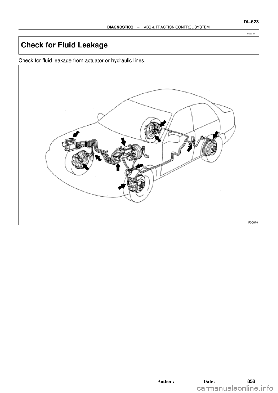
Check for Fluid Leakage
Check for fluid leakage from actuator or hydraulic lines.
DI050±03
Page 2163 of 4592

DI±12
± DIAGNOSTICSENGINE
SHORT FT #1
Short±term Fuel Trim Bank 10 ± 20 %
LONG FT #1Long±term Fuel Trim Bank 10 ± 20 %
ENGINE SPDEngine SpeedIdling: 650 ± 750 rpm
VEHICLE SPDVehicle SpeedVehicle Stopped: 0 km/h (0 mph)
IGN ADVANCEIgnition Advance: Ignition Timing of Cylinder No.1Idling: BTDC 0 ± 10°
INTAKE AIRIntake Air Temp. Sensor ValueEquivalent to Ambient Temp.
MAPAbsolute Pressure inside Intake ManifoldIdling: 20 ± 51 kPa
Racing without load (2,500 rpm): 17 ± 48 kPa
THROTTLE POSVoltage Output of Throttle Position Sensor Calcu-
lated as a percentage: 0 V "0 %, 5 V "100 %Throttle Fully Closed: 6 ± 16 %
Throttle Fully Open: 64 ± 98 %
O2S B1 S1Voltage Output of Heated Oxygen Sensor Bank 1
Sensor 1Idling: 0.1 ± 0.9 V (0.56 ± 0.76 V*2)
O2FT B1 S1Heated Oxygen Sensor Fuel Trim Bank 1 Sensor
1 (Same as SHORT FT #1)0 ± 20 %
A/FS B1 S1Voltage Output of A/F SensorIdling: 2.8 ± 3.8 V
A/FFT B1 S1A/F Sensor Fuel Trim (Same as SHORT FT #1)0 ± 20 %
O2S B1 S2Voltage Output of Heated Oxygen Sensor Bank 1
Sensor 2Driving at 50 km/h (31 mph): 0.05 ± 0.95 V
*1: If no conditions are specifically stated for ºldlingº, it means the shift lever is at N or P position, the A/C
switch is OFF and all accessory switches are OFF.
*
2: When you use the OBD II scan tool (excluding TOYOTA hand±held tester).
(b) TOYOTA Enhanced Signals.
TOYOTA hand±held tester displayMeasurement ItemNormal Condition*
MISFIRE RPMEngine RPM for first misfire rangeMisfire 0: 0 rpm
MISFIRE LOADEngine load for first misfire rangeMisfire 0: 0 g/r
INJECTORFuel injection time for cylinder No.1Idling: 2.9 ± 5.1 ms
IAC DUTY RATIOIntake Air Control Valve Duty Ratio
Opening ratio rotary solenoid type IAC valveIdling: 25 ± 62 %
STARTER SIGStarter SignalCranking: ON
CTP SIGClosed Throttle Position SignalThrottle fully closed: ON
A/C SIGA/C Switch SignalA/C ON: ON
PNP SIGPark/Neutral Position Switch SignalP or N position: ON
ELECTCL LOAD SIGElectrical Load SignalDefogger S/W ON: ON
STOP LIGHT SWStop Light Switch SignalStop light switch ON: ON
PS OIL PRESS SWPower Steering Oil Pressure Switch SignalTurn steering wheel: ON
FC IDLFuel Cut Idle: Fuel cut when throttle valve fully
closed, during decelerationFuel cut operating: ON
FC TAUFuel Cut TAU: Fuel cut during very light loadFuel cut operating: ON
CYL#1, CYL#2, CYL#3, CYL#4Abnormal revolution variation for each cylinder0 %
IGNITIONTotal number of ignition for every 1,000 revolu-
tions0 ± 2,000
EGR SYSTEMEGR system operating conditionIdling: OFF
FUEL PUMPFuel Pump SignalIdling: ON
A/C CUT SIGA/C Cut SignalA/C S/W OFF: ON
A/C MAG CLUTCHA/C Switch SignalA/C ON: ON
EVAP (PURGE) VSVEVAP VSV SignalVSV operating: Avove 30 %
Page 2165 of 4592

DI00I±11
DI±14
± DIAGNOSTICSENGINE
DIAGNOSTIC TROUBLE CODE CHART
HINT:
Parameters listed in the chart may not be exactly the same as your reading due to the type of instrument
or other factors.
If a malfunction code is displayed during the DTC check in check mode, check the circuit for that code listed
in the table below. For details of each code, turn to the page referred to under the ''See page '' for the respec-
tive ''DTC No.'' in the DTC chart.
1. SAE CONTROLLED
DTC No.
(See page)Detection ItemTrouble AreaMIL*Memory
P0105
(DI±22)Manifold Absolute Pressure/
Barometric Pressure Circuit Mal-
function�Open or short in manifold absolute pressure sensor circuit
�Manifold absolute pressure sensor
�ECM
��
P0106
(DI±25)Manifold Absolute Pressure Cir-
cuit Range/Performance Prob-
lem�Vacuum line
�Manifold absolute pressure sensor��
P0110
(DI±26)Intake Air Temp. Circuit Malfunc-
tion�Open or short in intake air temp. sensor circuit
�Intake air temp. sensor
�ECM
��
P0115
(DI±30)Engine Coolant Temp. Circuit
Malfunction�Open or short in engine coolant temp. sensor circuit
�Engine coolant temp. sensor
�ECM
��
P0116
(DI±34)Engine Coolant Temp. Circuit
Range/Performance Problem�Cooling system
�Engine coolant temp. sensor��
P0120
(DI±35)Throttle/Pedal Position Sensor/
Switch ºAº Circuit Malfunction�Open or short in throttle position sensor circuit
�Throttle position sensor
�ECM
��
P0121
(DI±39)Throttle/Pedal Position Sensor/
Switch ºAº Circuit Range/Perfor-
mance Problem
�Throttle position sensor��
P0125
(DI±40)Insufficient Coolant Temp. for
Closed Loop Fuel Control
�Open or short in A/F sensor (bank 1 sensor 1) circuit
�A/F sensor (bank 1 sensor 1)
�Air induction system
�EGR system
�Fuel pressure
�Injector
�Gas leakage on exhaust system
�ECM
��
P0136
(DI±45)Oxygen Sensor Circuit Malfunc-
tion (Bank 1 Sensor 2)�Open or short in heated oxygen sensor circuit
�Heated oxygen sensor��
P0141
(DI±47)Oxygen Sensor Heater Circuit
Malfunction (Bank 1 Sensor 2)�Open or short in heater circuit of heated oxygen sensor
�Heated oxygen sensor heater
�ECM
��
P0171
(DI±49)System too Lean (Fuel Trim)
�Air induction system
�Injector blockage
�Manifold absolute pressure sensor
�Engine coolant temp. sensor
�Fuel shutoff valve for delivery pipe
�Gas leakage on exhaust system
�Open or short in A/F sensor (bank 1 sensor 1) circuit
�A/F sensor (bank 1 sensor 1)
�ECM
��
Page 2166 of 4592
System too Rich (Fuel Trim)
�Injector leak, blockage
�Manifold absolute pressure sensor
�Engine coolant temp. sensor
�Ignition system
�Fuel shutoff valve for")
± DIAGNOSTICSENGINE
DI±15
P0172
(DI±49)System too Rich (Fuel Trim)
�Injector leak, blockage
�Manifold absolute pressure sensor
�Engine coolant temp. sensor
�Ignition system
�Fuel shutoff valve for delivery pipe
�Gas leakage on exhaust system
�Open or short in A/F sensor (bank 1 sensor 1) circuit
�A/F sensor (bank 1 sensor 1)
�ECM
��
P0180
(DI±54)Fuel Temperature Sensor ºAº
Circuit Malfunction
�Open or short in fuel temperature sensor circuit for delivery
pipe
�Fuel temperature sensor for delivery pipe
�ECM
��
P0190
(DI±56)Fuel Rail Pressure Sensor Cir-
cuit Malfunction�Open or short in fuel pressure sensor circuit for delivery pipe
�Fuel pressure sensor for delivery pipe
�ECM
��
P0335
(DI±59)Crankshaft Position Sensor ºAº
Circuit Malfunction
�Open or short in crankshaft position sensor circuit
�Crankshaft position sensor
�Crankshaft timing pulley
�ECM
��
P0340
(DI±61)Camshaft Position Sensor Circuit
Malfunction
�Open or short in camshaft position sensor circuit
�Camshaft position sensor
�Camshaft timing pulley
�ECM
��
P0400
(DI±63)Exhaust Gas Recirculation Flow
Malfunction
�Vacuum or EGR hose is connected to wrong post
�Open or short in VSV circuit for EGR
�VSV for EGR
�EGR system
�EGR vacuum modulator
�EGR valve
�Manifold absolute pressure sensor
�ECM
��
P0500
(DI±69)Vehicle Speed Sensor Malfunc-
tion
�Combination meter
�Open or short in vehicle speed sensor circuit
�Vehicle speed sensor
�ECM
��
P0505
(DI±72)Idle Control System Malfunction
�Open or short in IAC valve circuit
�IAC valve is stuck or closed
�Open or short in A/C switch circuit
�Air induction system
�ECM
��
*: MIL lights up
2. MANUFACTURER CONTROLLED
DTC No.
(See Page)Detection ItemTrouble AreaMIL*Memory
P1130
(DI±79)A/F Sensor Circuit Range/Perfor-
mance Malfunction (Bank 1 Sen-
sor 1)
�Open or short in A/F sensor circuit
�A/F sensor
�Air induction system
�EGR system
�Fuel pressure
�Injector
�ECM
��
P1135
(DI±84)A/F Sensor Heater Circuit Mal-
function (Bank 1 Sensor 1)�Open or short in heater circuit of A/F sensor
�A/F sensor heater
�ECM
��
Page 2168 of 4592
DI1JS±04
A09176
Crankshaft Position
SensorVSV for EGR DLC1
Camshaft Position
Sensor InjectorECMThrottle Position SensorManifold Absolute
Pressure Sensor
Combination Meter
for Speedometer
DLC3
Heated Oxygen
Sensor (Bank 1
Sensor 2)
Intake Air Temperature
Sensor
Idle Air Control
Valve
Ignition Coil (No.1, No.2) Park/Neutral
Position Switch Engine Coolant
Temperature
Sensor A/F Sensor
Bank 1
Sensor 1)
Fuel Pressure
Sensor for
Delivery Pipe
Fuel Pressure Regulator
Fuel Temperature
Sensor for Fuel
Tank
Fuel Temperature
Sensor for
Delivery Pipe
Fuel Shutoff Valve for
Pressure Regulator
Fuel Pressure Sensor
for Fuel Pipe
Fuel Shutoff Valve
for Fuel Tank
± DIAGNOSTICSENGINE
DI±17
PARTS LOCATION
Page 2173 of 4592

2.4V
100mmHg
20(840)
60kPa
(112)
Output Voltage
DI±22
± DIAGNOSTICSENGINE
CIRCUIT INSPECTION
DTC P0105 Manifold Absolute Pressur")
DI00M±07
P01242
Manifold Absolute Pressure450
150 1.2
750 3.6 (3.96)
2.4V
100mmHg
20(840)
60kPa
(112)
Output Voltage
DI±22
± DIAGNOSTICSENGINE
CIRCUIT INSPECTION
DTC P0105 Manifold Absolute Pressure/Barometric
Pressure Circuit Malfunction
CIRCUIT DESCRIPTION
By a built±in sensor unit, the manifold absolute pressure sensor
detects the intake manifold pressure as a voltage. The ECM
then determines the basic injection duration and basic injection
advance angle based on this voltage. Since the manifold abso-
lute pressure sensor does not use the atmospheric pressure as
a criterion, but senses the absolute pressure inside the intake
manifold (the pressure in proportion to the present absolute
vacuum 0), it is not influenced by fluctuations in the atmospheric
pressure due to high altitude and other factors. This permits it
to control the air±fuel ratio at the proper lever under all condi-
tions.
DTC No.DTC Detecting ConditionTrouble Area
P0105Open or short in manifold absolute pressure sensor circuit
�Open or short in manifold absolute pressure sensor circuit
�Manifold absolute pressure sensor
�ECM
HINT:
After confirming DTC P0105, use the OBD II scan tool or TOYOTA hand±held tester to confirm the manifold
absolute pressure from the CURRENT DATA.
Manifold Absolute Pressure (kPa)Malfunction
Approx. 0�PIM circuit short
130 or more
�VC circuit open or short
�PIM circuit open
�E2 circuit open