Page 646 of 4592
N20557
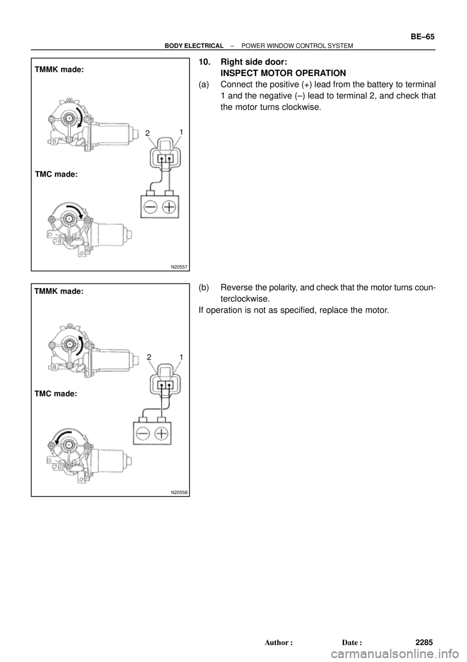
TMMK made:
TMC made:1
2
N20558
TMMK made:
TMC made:1 2
± BODY ELECTRICALPOWER WINDOW CONTROL SYSTEM
BE±65
2285 Author�: Date�:
10. Right side door:
INSPECT MOTOR OPERATION
(a) Connect the positive (+) lead from the battery to terminal
1 and the negative (±) lead to terminal 2, and check that
the motor turns clockwise.
(b) Reverse the polarity, and check that the motor turns coun-
terclockwise.
If operation is not as specified, replace the motor.
Page 647 of 4592
 Discon")
I21314
1
2
I21315
2
1
I21312
21
BE±66
± BODY ELECTRICALPOWER WINDOW CONTROL SYSTEM
2286 Author�: MH Date�: 3/7/02
11. Driver 's door:
INSPECT POWER WINDOW MOTOR PTC THERM-
ISTOR OPERATION
(a) Disconnect the connector from the master switch.
(b) Connect the positive (+) lead from the ammeter to termi-
nal 2 on the wire harness side connector and the negative
(±) lead to negative terminal of the battery.
(c) Connect the positive (+) lead from the battery to terminal
1 on the wire harness side connector, and raise the win-
dow to the fully position.
(d) Continue to apply voltage and check that the current
changes to less than 1 A within 4 to 90 seconds.
(e) Disconnect the leads from the terminals.
(f) Approximately 60 seconds later, connect the positive (+)
lead from the battery to terminal 2 and the negative (±)
lead to terminal 1, and check that the window begins to
descend.
If operation is not as specified, replace the motor.
12. Passenger 's door:
INSPECT POWER WINDOW MOTOR PTC THERM-
ISTOR OPERATION
(a) Disconnect the connector from the power window switch.
(b) Connect the positive (+) lead from the ammeter to termi-
nal 1 on the wire harness side connector and the negative
(±) lead to negative terminal of the battery.
(c) Connect the positive (+) lead from the battery to terminal
2 on the wire harness side connector, and raise the win-
dow to the fully position.
(d) Continue to apply voltage and check that the current
changes to less than 1 A within 4 to 90 seconds.
(e) Disconnect the leads from the terminals.
Page 648 of 4592
 Close(c) Open
A3 Type B:
± BODY ELECTRICALPOWER WINDOW CONTROL SYSTEM
BE±67
2287 Author�: Date�:
(f) Approximately 60 seconds later, connect the positive")
I21313
2
1
I12561
2
1
I12560
21
N20564
(b) Close(c) Open
A3 Type B:
± BODY ELECTRICALPOWER WINDOW CONTROL SYSTEM
BE±67
2287 Author�: Date�:
(f) Approximately 60 seconds later, connect the positive (+)
lead from the battery to terminal 1 and the negative (±)
lead to terminal 2, and check that the window begins to
descend.
If operation is not as specified, replace the motor.
13. Rear Door:
INSPECT POWER WINDOW MOTOR PTC THERM-
ISTOR OPERATION
(a) Disconnect the connector from the power window switch.
(b) Connect the positive (+) lead from the ammeter to termi-
nal 1 on the wire harness side connector and the negative
(±) lead to negative terminal of the battery.
(c) Connect the positive (+) lead from the battery to terminal
2 on the wire harness side connector, and raise the win-
dow to the fully position.
(d) Continue to apply voltage and check that the current
changes to less than 1 A within 4 to 90 seconds.
(e) Disconnect the leads from the terminals.
(f) Approximately 60 seconds later, connect the positive (+)
lead from the battery to terminal 2 and the negative (±)
lead to terminal 1, and check that the window begins to
descend.
If operation is not as specified, replace the motor.
14. Key±off power window signal:
INSPECT INTEGRATION RELAY (TYPE B) OPERA-
TION
HINT:
When the relay circuit is as specified, inspect the key±off power
window signal.
(a) Connect the positive (+) lead from the voltmeter to termi-
nal A3 and the negative (±) lead to body ground.
(b) Close the door with ignition switch turned to LOCK or
ACC, and check that the meter needle indicates battery
positive voltage.
(c) Open the door and check that the meter needle indicates
0 V.
Page 649 of 4592
 Close (c) Open
A12 Type C:
N20567
A12 Type C: BE±68
± BODY ELECTRICALPOWER WINDOW CONTROL SYSTEM
2288 Author�: MH Date�: 3/7/02
(d) Turn the ignition switch ON and check")
N20565
A3 Type B:
N20566
(b) Close (c) Open
A12 Type C:
N20567
A12 Type C: BE±68
± BODY ELECTRICALPOWER WINDOW CONTROL SYSTEM
2288 Author�: MH Date�: 3/7/02
(d) Turn the ignition switch ON and check that the meter
needle indicates battery positive voltage again.
If operation is not as specified, replace the relay.
15. Key±off power window signal:
INSPECT INTEGRATION RELAY (TYPE C) OPERA-
TION
HINT:
When the relay circuit is as specified, inspect the key±off power
window signal.
(a) Connect the positive (+) lead from the voltmeter to termi-
nal A12 and the negative (±) lead to body ground.
(b) Close the door with ignition switch turned to LOCK or
ACC, and check that the meter needle indicates battery
positive voltage.
(c) Open the door and check that the meter needle indicates
0 V.
(d) Turn the ignition switch ON and check that the meter
needle indicates battery positive voltage again.
If operation is not as specified, replace the relay.
16. INSPECT INTEGRATION RELAY CIRCUIT
(See page XX±XXX)
Page 650 of 4592
BE0AP±02
Z19053
Instrument Panel J/B No.1
� POWER M±Fuse
� CIG Fuse
� DOOR Fuse
� Integration Relay
Power Window Master Switch
� Door Lock Control SwitchDoor Key Lock and Unlock Switch
Door Lock Assembly
� Door Lock Motor
� Door Unlock Detection Switch
Door Lock Assembly
� Door Lock Motor
� Door Unlock Detection Switch
Door Lock Control Switch
± BODY ELECTRICALPOWER DOOR LOCK CONTROL SYSTEM
BE±69
2289 Author�: Date�:
POWER DOOR LOCK CONTROL SYSTEM
LOCATION
Page 669 of 4592
 Matlers that require atte")
N21545
NoiseGlass Printed Antenna
Signal
Radio
Noise
Noise
Noise
Noise
N21546
to Radio
Battery
Choke Coil
Noise
BE±88
± BODY ELECTRICALAUDIO SYSTEM
2308 Author�: Date�:
(b) Matlers that require attention when checking:
�Noise coming into the radio usually has no harm for
practical use as the noise protection is taken and it
is hardly thinkable for an extremely loud noise to
come in. When extremely loud noise comes into the
radio, check if the grounding is normal where the
antenna is installed.
�Check if all the regular noise prevention parts are
properly installed and if there is any installation of
non±authorized parts and non±authorized wiring.
�If you leave the radio out of tune (not tuning), it is
easy to diagnose the phenomenon as noise occurs
frequently.
(c) Antenna and noise:
Electronic signal received by the antenna will reach to the
radio transmitting through the core wire of the coaxial
cable. Any noise wave other than radio wave is mixed into
this core wire, that naturally causes noise in the radio and
poor sound quality. In order to prevent these noises from
mixing into the radio, the core wire inside the coaxial cable
is covered with a mesh wire called shield wire. This shield
wire shelters the noise and transmits it to the ground, thus
preventing noise from mixing in. If this shield wire has
grounding failure, that causes noise.
(d) Choke coil and noise:
The choke coil is connected in the rear window defogger
circuit. This is conneted so to prevent noise from mixing
into the radio by making the noise current included in the
power source of the rear window defogger flow to the
ground.
Page 694 of 4592

I01475
25 Noise NOISE PRODUCED WHEN ENGINE STARTS
Whistling noise which becomes high±pitched when
accelerator strongly depressed, disappears shortly
after engine stops.Generator noise.
Whining noise occurs when A/C is operating. A/C noise.
Scratching noise occurs during sudden acceleration,
driving on rough roads or when ignition switch is turned
on.Fuel gauge noise.
Clicking sound heard when horn button is pressed,
then released. Whirring/ grating sound when pressed
continuously.Horn noise.
Murmuring sound stops when engine stops. Ignition noise.Ye s
No
No
No
No
NoYe s
Ye s
Ye s
Ye s
Tick±tock noise occurs in co±ordination with
blinking of flasher.
Noise occurs during window washer operation. Washer noise.Turn signal noise.
No
NoYe s
Ye s
Scratching noise occurs while engine is running
and continues for a while even after engine stops.
Scraping noise in time with wiper beat.Engine coolant temp. gauge noise.
Wiper noise.
Other type of noise.No
NoYe s
Ye s
± BODY ELECTRICALAUDIO SYSTEM
BE±113
2333 Author�: Date�:
Page 724 of 4592

(A541E)
4. Wire Harne")
BE±8
± BODY ELECTRICALBODY ELECTRICAL SYSTEM
2228 Author�: Date�:
Shift indicator lights do not light up.
1. Bulb
2. Meter Circuit Plate
3. Park/Neutral Position Switch (A140E)
(A541E)
4. Wire Harness±
BE±46
DI±424
DI±479
±
Only one shift indicator does not light up.1. Bulb
2. Meter Circuit Plate±
BE±46
Malfunction indicator light does not light up.
1. Bulb
2. ECM
3. Meter Circuit Plate
4. Wire Harness±
±
BE±46
±
SLIP indicator light does not light up.
1. Bulb
2. Traction ECU
3. Meter Circuit Plate
4. Wire Harness±
±
BE±46
±
TRAC OFF indicator light does not light up.
1. Bulb
2. Traction ECU
3. Meter Circuit Plate
4. Wire Harness±
±
BE±46
±
Security indicator light does not light up.
1. Bulb
2. Security ECU
3. Meter Circuit Plate
4. Wire Harness±
±
BE±46
±
Indicator lights do not light up. (Except Turn, Hi±beam and
security)1. GAUGE Fuse (I/P J/B No.1)
2. Wire Harness±
±
DEFOGGER SYSTEM
SymptomSuspect AreaSee page
All defogger systems do not operate.
1. DEFOG M±Fuse (I/P J/B No.1)
2. HTR Fuse (I/P J/B No.1)
3. Defogger Relay (I/P J/B No.1)
4. Defogger Switch
5. Wire Harness±
±
BE±56
BE±56
±
Rear window defogger does not operate.
1. Defogger Wire
2. Choke Coil
3. Wire HarnessBE±56
±
±
Mirror defogger does not operate.
1. MIR/HTR Fuse (I/P J/B No.1)
2. Mirror Defogger
3. Wire Harness±
BE±56
±
POWER WINDOW CONTROL SYSTEM
SymptomSuspect AreaSee page
Power window does not operate (ALL).
(Power Door Lock does not operate)1. POWER M±Fuse (I/P J/B No.1)
2. Power Main Relay (I/P J/B No.1)
3. Wire Harness±
BE±60
±
Power window does not operate (ALL).
(Power Door Lock is normal)1. Ignition Switch
2. Power Window Master Switch
3. Wire HarnessBE±14
BE±60
±
ºOne Touch Power Window Systemº does not operate.1. Power Window Master SwitchBE±60
Only one window glass does not move.
1. Power Window Master Switch
2. Power Window Switch
3. Power Window Motor
4. Wire HarnessBE±60
BE±60
BE±60
±
ºWindow Lock Systemº does not operate.1. Power Window Master SwitchBE±60