Page 1139 of 4592
CL03M±02
Q10089
1MZ±FE:
5S±FE:SST
Flywheel
Side
SST
Q10084
SST
1
Matchmarks
4
2
6
35
Q10072
SST
± CLUTCHCLUTCH UNIT
CL±21
1800 Author�: Date�:
INSTALLATION
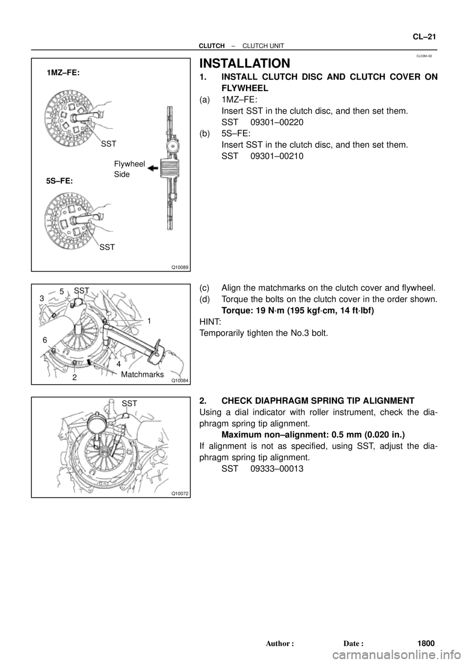
1. INSTALL CLUTCH DISC AND CLUTCH COVER ON
FLYWHEEL
(a) 1MZ±FE:
Insert SST in the clutch disc, and then set them.
SST 09301±00220
(b) 5S±FE:
Insert SST in the clutch disc, and then set them.
SST 09301±00210
(c) Align the matchmarks on the clutch cover and flywheel.
(d) Torque the bolts on the clutch cover in the order shown.
Torque: 19 N´m (195 kgf´cm, 14 ft´lbf)
HINT:
Temporarily tighten the No.3 bolt.
2. CHECK DIAPHRAGM SPRING TIP ALIGNMENT
Using a dial indicator with roller instrument, check the dia-
phragm spring tip alignment.
Maximum non±alignment: 0.5 mm (0.020 in.)
If alignment is not as specified, using SST, adjust the dia-
phragm spring tip alignment.
SST 09333±00013
Page 2568 of 4592
EM084±04
S05609
S05249
S05296
S05597
± ENGINE MECHANICAL (5S±FE)TIMING BELT
EM±17
1189 Author�: Date�:
REMOVAL
1. REMOVE GENERATOR (See page CH±6)
2. REMOVE RH FRONT WHEEL
3. REMOVE RH FRONT FENDER APRON SEAL
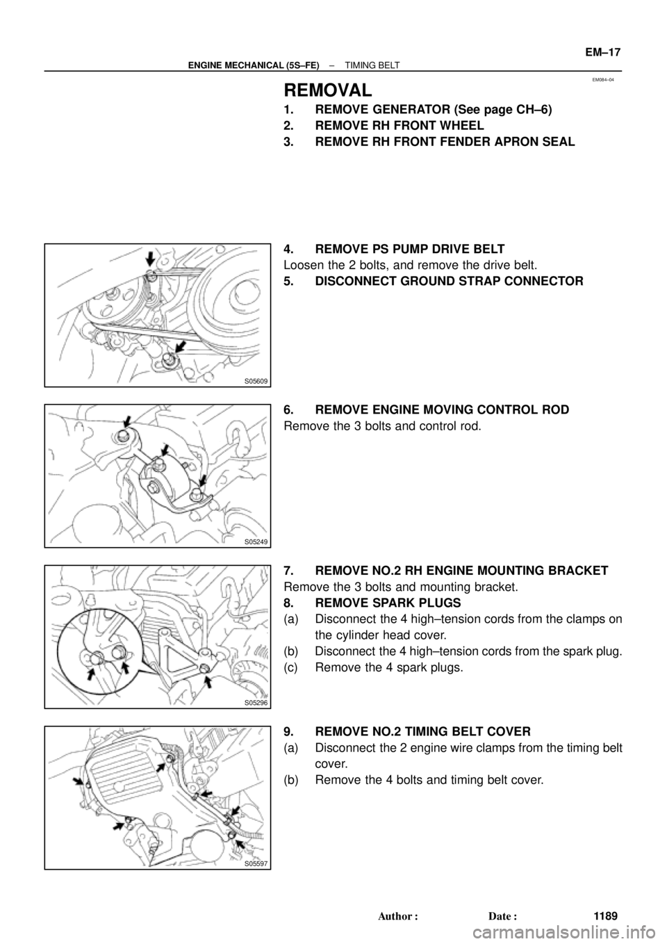
4. REMOVE PS PUMP DRIVE BELT
Loosen the 2 bolts, and remove the drive belt.
5. DISCONNECT GROUND STRAP CONNECTOR
6. REMOVE ENGINE MOVING CONTROL ROD
Remove the 3 bolts and control rod.
7. REMOVE NO.2 RH ENGINE MOUNTING BRACKET
Remove the 3 bolts and mounting bracket.
8. REMOVE SPARK PLUGS
(a) Disconnect the 4 high±tension cords from the clamps on
the cylinder head cover.
(b) Disconnect the 4 high±tension cords from the spark plug.
(c) Remove the 4 spark plugs.
9. REMOVE NO.2 TIMING BELT COVER
(a) Disconnect the 2 engine wire clamps from the timing belt
cover.
(b) Remove the 4 bolts and timing belt cover.
Page 2579 of 4592
S05596
S05296
S05249
S05609
EM±28
± ENGINE MECHANICAL (5S±FE)TIMING BELT
1200 Author�: Date�:
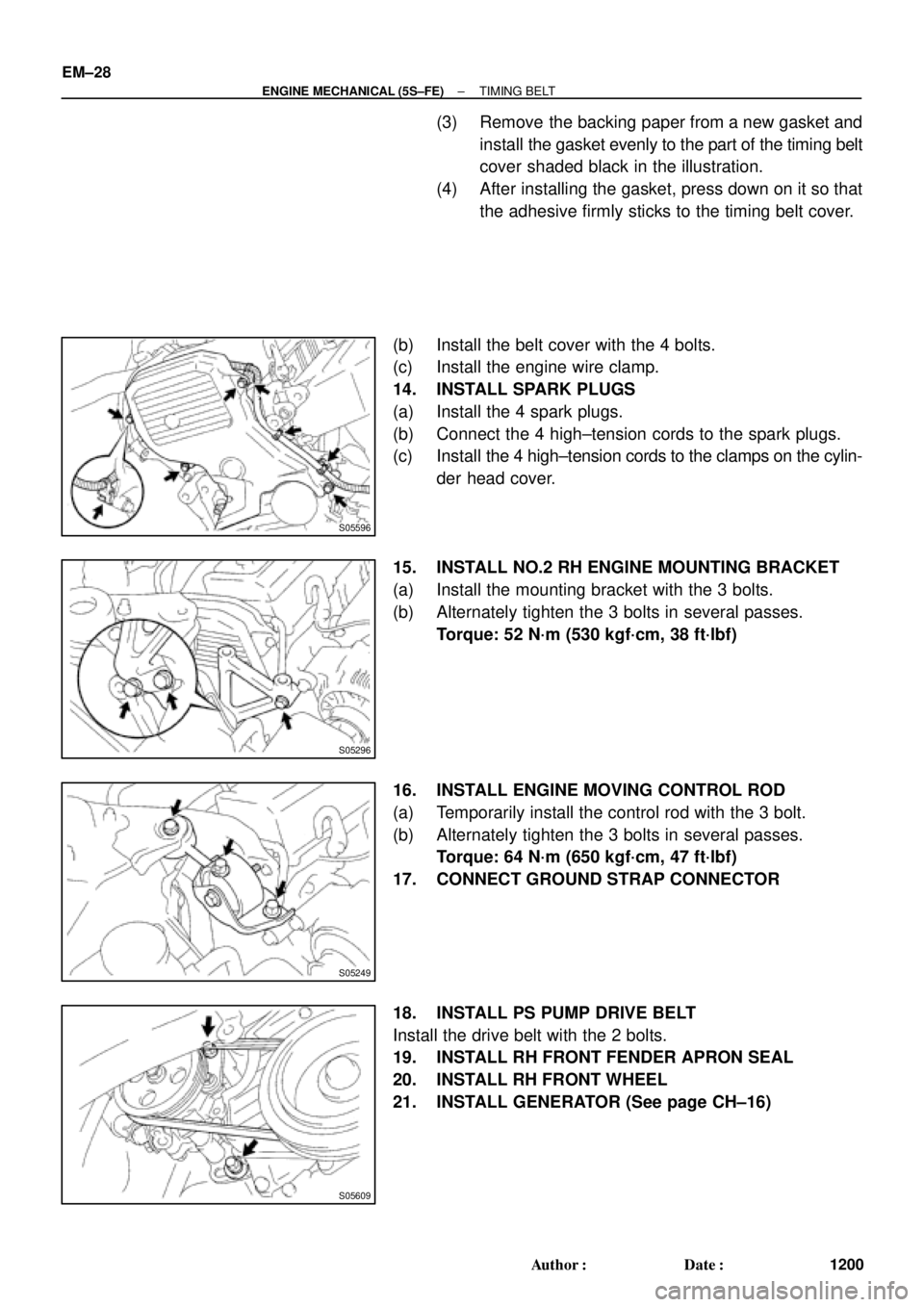
(3) Remove the backing paper from a new gasket and
install the gasket evenly to the part of the timing belt
cover shaded black in the illustration.
(4) After installing the gasket, press down on it so that
the adhesive firmly sticks to the timing belt cover.
(b) Install the belt cover with the 4 bolts.
(c) Install the engine wire clamp.
14. INSTALL SPARK PLUGS
(a) Install the 4 spark plugs.
(b) Connect the 4 high±tension cords to the spark plugs.
(c) Install the 4 high±tension cords to the clamps on the cylin-
der head cover.
15. INSTALL NO.2 RH ENGINE MOUNTING BRACKET
(a) Install the mounting bracket with the 3 bolts.
(b) Alternately tighten the 3 bolts in several passes.
Torque: 52 N´m (530 kgf´cm, 38 ft´lbf)
16. INSTALL ENGINE MOVING CONTROL ROD
(a) Temporarily install the control rod with the 3 bolt.
(b) Alternately tighten the 3 bolts in several passes.
Torque: 64 N´m (650 kgf´cm, 47 ft´lbf)
17. CONNECT GROUND STRAP CONNECTOR
18. INSTALL PS PUMP DRIVE BELT
Install the drive belt with the 2 bolts.
19. INSTALL RH FRONT FENDER APRON SEAL
20. INSTALL RH FRONT WHEEL
21. INSTALL GENERATOR (See page CH±16)
Page 2625 of 4592
S05531
Wire
Bracket
Ground
Strap
S05314
M/T EM±74
± ENGINE MECHANICAL (5S±FE)ENGINE UNIT
1246 Author�: Date�:
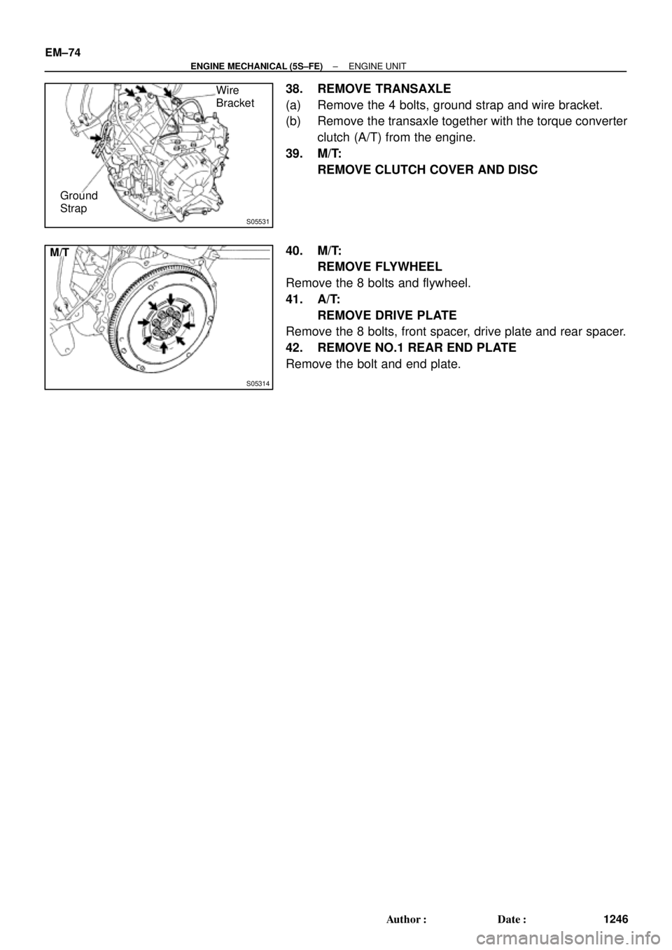
38. REMOVE TRANSAXLE
(a) Remove the 4 bolts, ground strap and wire bracket.
(b) Remove the transaxle together with the torque converter
clutch (A/T) from the engine.
39. M/T:
REMOVE CLUTCH COVER AND DISC
40. M/T:
REMOVE FLYWHEEL
Remove the 8 bolts and flywheel.
41. A/T:
REMOVE DRIVE PLATE
Remove the 8 bolts, front spacer, drive plate and rear spacer.
42. REMOVE NO.1 REAR END PLATE
Remove the bolt and end plate.
Page 2626 of 4592
EM08G±04
EM7333
Z18989
M/T
1
3
5
8
2 4 67
S05531
Wire
Bracket
Ground
Strap
± ENGINE MECHANICAL (5S±FE)ENGINE UNIT
EM±75
1247 Author�: Date�:
INSTALLATION
1. INSTALL NO.1 REAR END PLATE
Install the end plate with the bolt.
Torque: 9.3 N´m (95 kgf´cm, 82 in.´lbf)
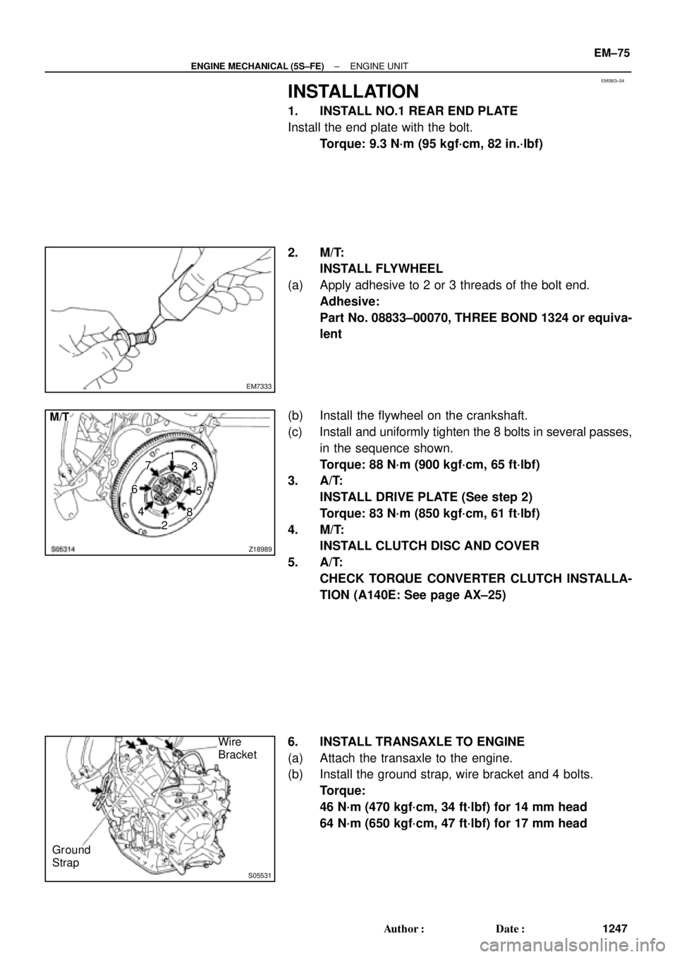
2. M/T:
INSTALL FLYWHEEL
(a) Apply adhesive to 2 or 3 threads of the bolt end.
Adhesive:
Part No. 08833±00070, THREE BOND 1324 or equiva-
lent
(b) Install the flywheel on the crankshaft.
(c) Install and uniformly tighten the 8 bolts in several passes,
in the sequence shown.
Torque: 88 N´m (900 kgf´cm, 65 ft´lbf)
3. A/T:
INSTALL DRIVE PLATE (See step 2)
Torque: 83 N´m (850 kgf´cm, 61 ft´lbf)
4. M/T:
INSTALL CLUTCH DISC AND COVER
5. A/T:
CHECK TORQUE CONVERTER CLUTCH INSTALLA-
TION (A140E: See page AX±25)
6. INSTALL TRANSAXLE TO ENGINE
(a) Attach the transaxle to the engine.
(b) Install the ground strap, wire bracket and 4 bolts.
Torque:
46 N´m (470 kgf´cm, 34 ft´lbf) for 14 mm head
64 N´m (650 kgf´cm, 47 ft´lbf) for 17 mm head
Page 2680 of 4592
EM04O±04
P18754
P18816
P18817
SST
P18819
SST
± ENGINE MECHANICAL (1MZ±FE)TIMING BELT
EM±15
1301 Author�: Date�:
REMOVAL
1. REMOVE RH FRONT WHEEL
2. REMOVE RH FENDER APRON SEAL
3. REMOVE GENERATOR DRIVE BELT
(See page CH±6)
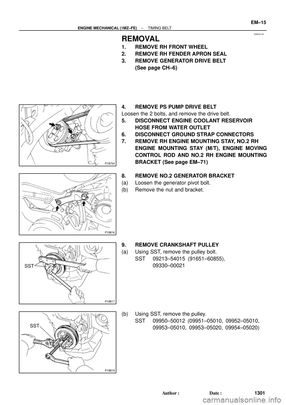
4. REMOVE PS PUMP DRIVE BELT
Loosen the 2 bolts, and remove the drive belt.
5. DISCONNECT ENGINE COOLANT RESERVOIR
HOSE FROM WATER OUTLET
6. DISCONNECT GROUND STRAP CONNECTORS
7. REMOVE RH ENGINE MOUNTING STAY, NO.2 RH
ENGINE MOUNTING STAY (M/T), ENGINE MOVING
CONTROL ROD AND NO.2 RH ENGINE MOUNTING
BRACKET (See page EM±71)
8. REMOVE NO.2 GENERATOR BRACKET
(a) Loosen the generator pivot bolt.
(b) Remove the nut and bracket.
9. REMOVE CRANKSHAFT PULLEY
(a) Using SST, remove the pulley bolt.
SST 09213±54015 (91651±60855),
09330±00021
(b) Using SST, remove the pulley.
SST 09950±50012 (09951±05010, 09952±05010,
09953±05010, 09953±05020, 09954±05020)
Page 2748 of 4592
EM051±04
S04921
P12946
P18761
P12389
SST
± ENGINE MECHANICAL (1MZ±FE)CYLINDER BLOCK
EM±83
1369 Author�: Date�:
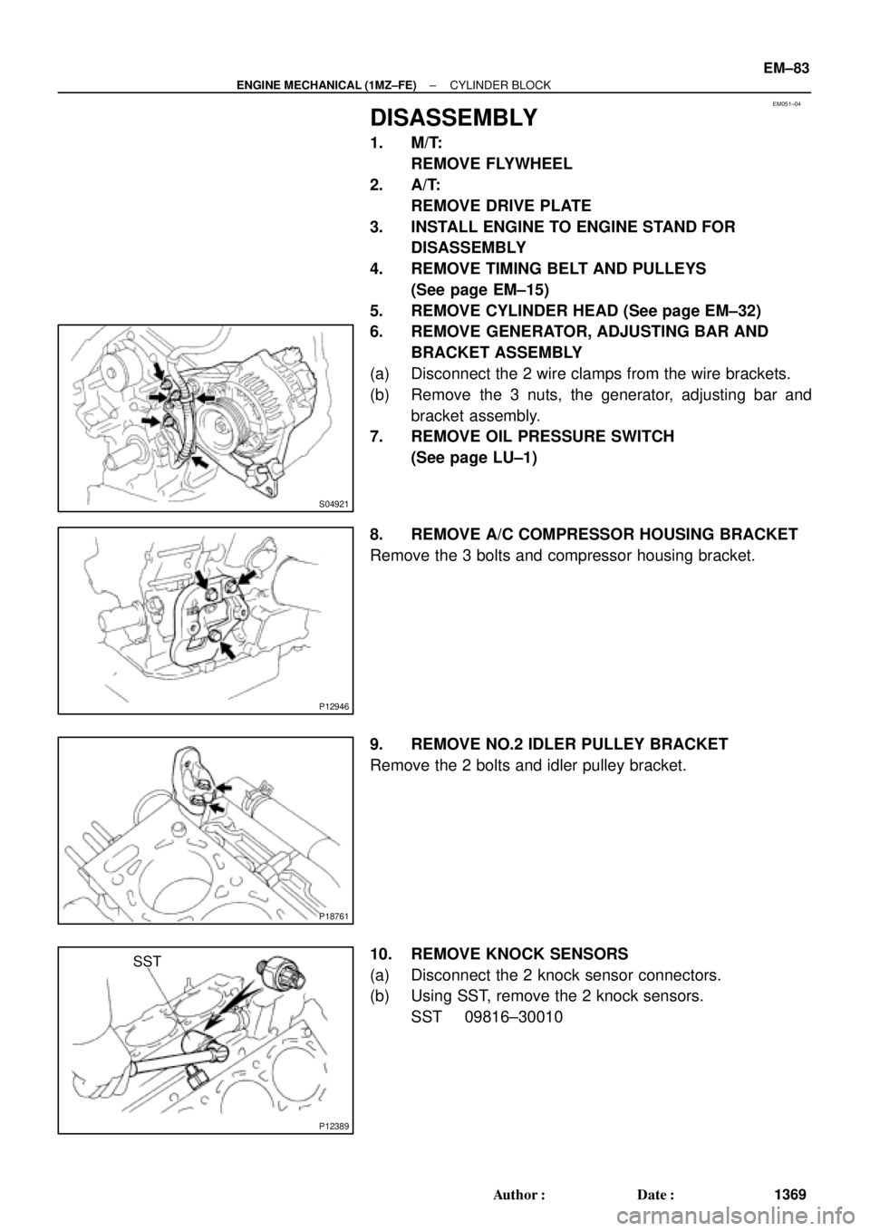
DISASSEMBLY
1. M/T:
REMOVE FLYWHEEL
2. A/T:
REMOVE DRIVE PLATE
3. INSTALL ENGINE TO ENGINE STAND FOR
DISASSEMBLY
4. REMOVE TIMING BELT AND PULLEYS
(See page EM±15)
5. REMOVE CYLINDER HEAD (See page EM±32)
6. REMOVE GENERATOR, ADJUSTING BAR AND
BRACKET ASSEMBLY
(a) Disconnect the 2 wire clamps from the wire brackets.
(b) Remove the 3 nuts, the generator, adjusting bar and
bracket assembly.
7. REMOVE OIL PRESSURE SWITCH
(See page LU±1)
8. REMOVE A/C COMPRESSOR HOUSING BRACKET
Remove the 3 bolts and compressor housing bracket.
9. REMOVE NO.2 IDLER PULLEY BRACKET
Remove the 2 bolts and idler pulley bracket.
10. REMOVE KNOCK SENSORS
(a) Disconnect the 2 knock sensor connectors.
(b) Using SST, remove the 2 knock sensors.
SST 09816±30010
Page 2775 of 4592
P00601
Adhesive
A05416
1
2 34 5
67
8
EM±110
± ENGINE MECHANICAL (1MZ±FE)CYLINDER BLOCK
1396 Author�: Date�:
30. INSTALL OIL PRESSURE SWITCH
(See page LU±1)
31. INSTALL GENERATOR, BRACKET AND
ADJUSTING BAR ASSEMBLY
Torque: 43 N´m (440 kgf´cm, 32 ft´lbf)
32. INSTALL CYLINDER HEAD (See page EM±57)
33. INSTALL TIMING PULLEYS AND BELT
(See page EM±21)
34. REMOVE ENGINE STAND
35. A/T:
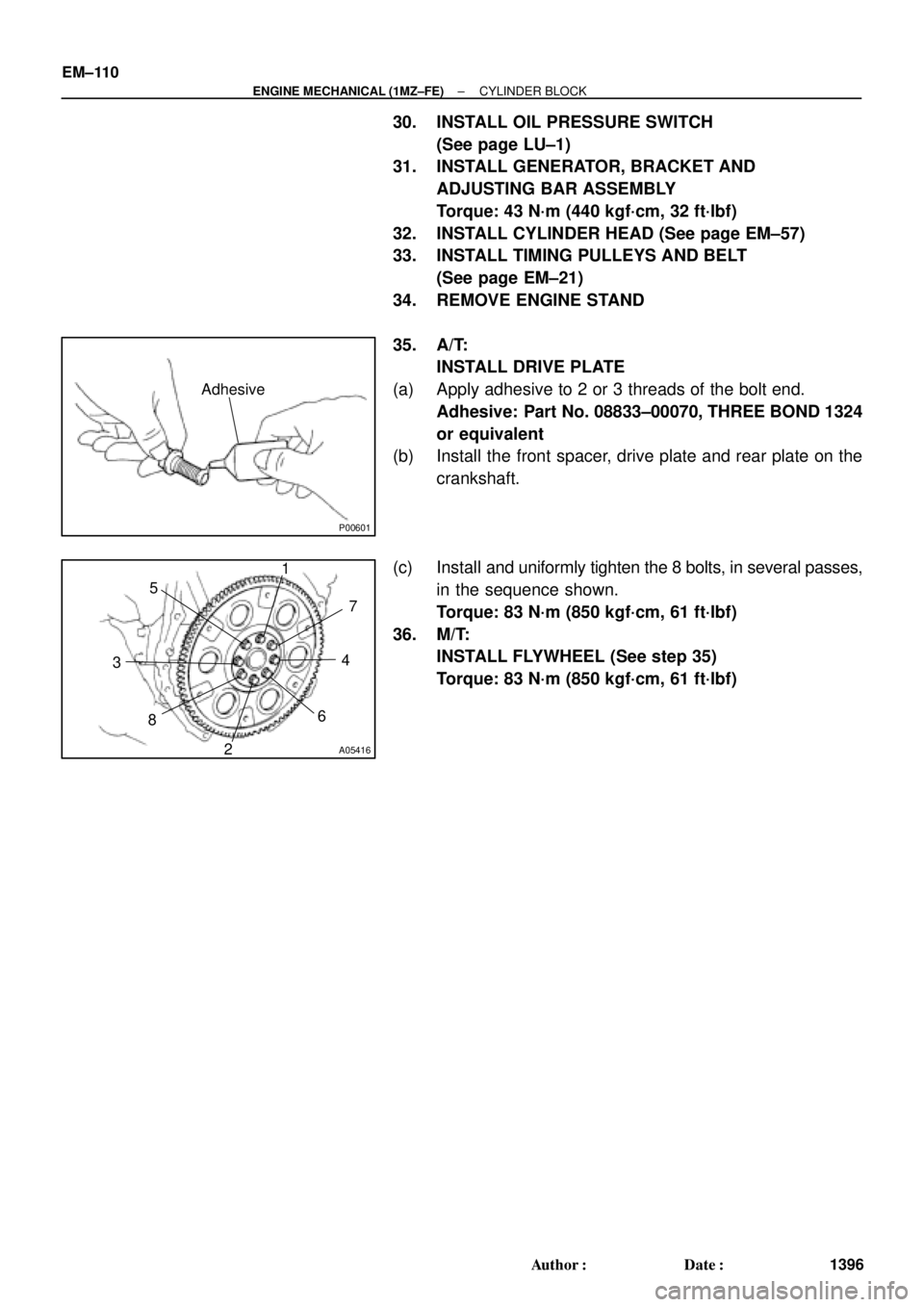
INSTALL DRIVE PLATE
(a) Apply adhesive to 2 or 3 threads of the bolt end.
Adhesive: Part No. 08833±00070, THREE BOND 1324
or equivalent
(b) Install the front spacer, drive plate and rear plate on the
crankshaft.
(c) Install and uniformly tighten the 8 bolts, in several passes,
in the sequence shown.
Torque: 83 N´m (850 kgf´cm, 61 ft´lbf)
36. M/T:
INSTALL FLYWHEEL (See step 35)
Torque: 83 N´m (850 kgf´cm, 61 ft´lbf)