Page 916 of 4592

BO0MB±01
N20950
Instrument Panel ReinforcementNN
DD
No.2 Instrumental Panel Bracket
No.1 Instrumental Panel Bracket
No.2 Instrumental Panel Brace
QQH N
N
N
N
GG
NG
NOB
NN
Instrument Panel Brace Mount
No.1 Instrument
Panel BraceFront Pillar Garnish
Front Pillar
GarnishFront
Passenger
Airbag
Assembly
20 (200, 14)
No.2 Side Defroster Nozzle
Cowl Side Trim
Front Door Openin
g
Cover
Instrument Panel
C
Remote Control
Mirror Hole Base
Upper Column
CoverHazard Warning
Switch
Lower Finish
PlateGlove Compartment
Door Finish PlateFront Door
Inside Scuff Plate
FFF
FJ
Glove
Compartment
No.2 Lower
Panel A
A
Cluster Finish
Panel
Lower Column
Cover
Front Door
Opening
Cover
Cowl Side
TrimD
DD
D
D
F
AA
Lower Panel
InsertCoin
BoxCombination SwitchCombination
MeterRadio Assembly
Center Cluster
Finish Panel
A/C
Control Assembly
35 (360, 26)
Steering
Wheel
Pad Steering Wheel No.1 Lower
Panel
Front Door
Inside Scuff PlateFront Console
Box
Center Console
Upper PanelF
F
B
B
Rear Console
Box
N´m (kgf´cm, ft´lbf) : Specified torque BO±72
± BODYINSTRUMENT PANEL
2420 Author�: Date�:
INSTRUMENT PANEL
COMPONENTS
Page 917 of 4592
N20951
A
Instrument Panel Wire Harness
No.1 Defroster Nozzle Garnish
Defroster Nozzle Assembly A
A
RH Side Defroster Duct Nozzle
No.1
Side Defroster
Duct Nozzle
A
A
A
A
A
ANo.2 Heater Duct to
Register
No.3 Instrument
Panel Register
Assembly K
K
K
K
K
K
No.1 Heater Duct to
RegisterAAA
No.1 Instrument Panel
Regigter AssemblyNo.2 Instrument
Panel Register
AssemblyInstrument
Panel Center
Bracket
Instrument PanelGlove Box
Light Assembly
± BODYINSTRUMENT PANEL
BO±73
2421 Author�: Date�:
Page 920 of 4592
 Using a screwdriver, remove the glove compartment door
finish plate to")
N20988
N21023
7 Clips
N21024
6 Clips BO±76
± BODYINSTRUMENT PANEL
2424 Author�: Date�:
8. REMOVE GLOVE COMPARTMENT ASSEMBLY
(a) Using a screwdriver, remove the glove compartment door
finish plate to the glove compartment box inside.
NOTICE:
When handling the airbag connector, be careful not to dam-
age the airbag wire harness.
HINT:
Tape the screwdriver tip before use.
(b) Pull up and disconnect the airbag connector.
(c) Remove the 4 screws, bolt and glove compartment as-
sembly.
9. REMOVE CENTER CONSOLE UPPER PANEL
Using a screwdriver, remove the panel, then disconnect the
connector.
HINT:
Tape the screwdriver tip before use.
10. REMOVE REAR CONSOLE BOX
Remove the 2 bolts, 2 screws and the console box.
11. REMOVE CENTER CLUSTER FINISH PANEL
Using a screwdriver, remove the panel, then disconnect the
connector.
HINT:
Tape the screwdriver tip before using.
12. REMOVE FRONT CONSOLE BOX
Remove the 2 screws and the front console box.
13. REMOVE RADIO ASSEMBLY
14. REMOVE A/C CONTROL ASSEMBLY
(See page AC±82)
15. REMOVE HAZARD WARNING SWITCH
16. REMOVE CLUSTER FINISH PANEL
(a) Remove the 2 screws.
(b) Using a screwdriver, remove the panel.
HINT:
Tape the screwdriver tip before use.
17. REMOVE COMBINATION METER
18. REMOVE REMOTE CONTROL MIRROR HOLE BASE
Page 923 of 4592
BO0MD±01
N21124
± BODYINSTRUMENT PANEL
BO±79
2427 Author�: Date�:
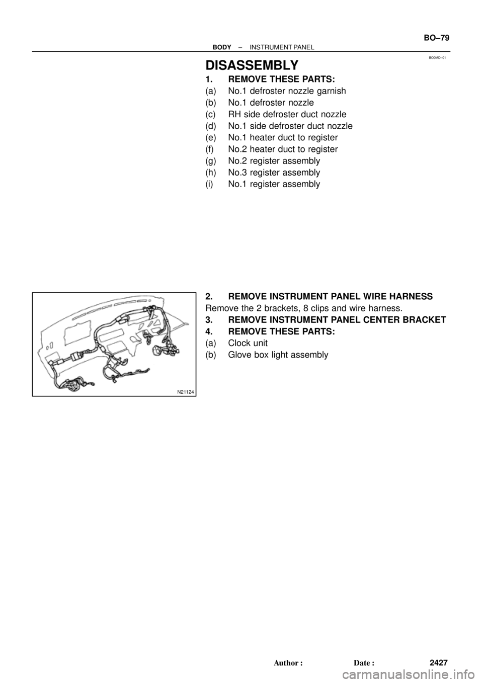
DISASSEMBLY
1. REMOVE THESE PARTS:
(a) No.1 defroster nozzle garnish
(b) No.1 defroster nozzle
(c) RH side defroster duct nozzle
(d) No.1 side defroster duct nozzle
(e) No.1 heater duct to register
(f) No.2 heater duct to register
(g) No.2 register assembly
(h) No.3 register assembly
(i) No.1 register assembly
2. REMOVE INSTRUMENT PANEL WIRE HARNESS
Remove the 2 brackets, 8 clips and wire harness.
3. REMOVE INSTRUMENT PANEL CENTER BRACKET
4. REMOVE THESE PARTS:
(a) Clock unit
(b) Glove box light assembly
Page 3179 of 4592
RS014±21
H08321
Front Passenger
Airbag Assembly
20 (205, 15)
N´m (kgf´cm, ft´lbf) : Specified torqueGlove Compartment Door
Finish PlateGlove Compartment Box
Cowl Side Trim RH
Front Door Scuff Plate RH
± SUPPLEMENTAL RESTRAINT SYSTEMFRONT PASSENGER AIRBAG ASSEMBLY
RS±27
2172 Author�: Date�:
FRONT PASSENGER AIRBAG ASSEMBLY
COMPONENTS
Page 3180 of 4592

RS02P±03
H03287
W03509
RS±28
± SUPPLEMENTAL RESTRAINT SYSTEMFRONT PASSENGER AIRBAG ASSEMBLY
2173 Author�: Date�:
REMOVAL
NOTICE:
�If the wiring connector of the SRS is disconnected
and the ignition switch is in ON or ACC position, DTCs
will be recorded.
�Never use the airbag parts from another vehicle.
When replacing parts, replace them with new parts.
HINT:
For step 2 to 4, refer to page BO±75.
1. DISCONNECT AIRBAG CONNECTOR
(a) Remove the glove compartment door finish plate inside
the glove compartment box.
NOTICE:
When handling the airbag connector, take care not to dam-
age the airbag wire harness.
(b) Pull up the connector.
(c) Disconnect the front passenger airbag connector.
2. REMOVE FRONT DOOR SCUFF PLATE
3. REMOVE COWL SIDE TRIM
4. REMOVE GLOVE COMPARTMENT BOX
5. REMOVE FRONT PASSENGER AIRBAG ASSEMBLY
Remove the 2 bolts, 4 nuts and front passenger airbag assem-
bly.
CAUTION:
�Do not store the front passenger airbag assembly
with the airbag deployment side facing downward.
�Never disassemble the front passenger airbag as-
sembly.
Page 3190 of 4592

RS019±05
W03509
H03288
RS±38
± SUPPLEMENTAL RESTRAINT SYSTEMFRONT PASSENGER AIRBAG ASSEMBLY
2183 Author�: Date�:
INSTALLATION
NOTICE:
Never use airbag parts from another vehicle. When replac-
ing parts, replace them with new parts.
HINT:
For step 2 to 4, refer to page BO±81.
1. INSTALL FRONT PASSENGER AIRBAG ASSEMBLY
(a) Install the front passenger airbag assembly with the 2
bolts.
Torque: 20 N´m (205 kgf´cm, 15 ft´lbf)
(b) Install the 4 nuts.
CAUTION:
�Make sure that no foreign objects are trapped be-
tween the airbag bag and the module.
�Do not damage the strap when installing the module.
NOTICE:
If the front passenger airbag assembly has been dropped,
or there are cracks, dents or other defects in the case or
connector, replace the front passenger airbag assembly
with a new one.
2. INSTALL GLOVE COMPARTMENT BOX
3. INSTALL COWL SIDE TRIM
4. INSTALL FRONT DOOR SCUFF PLATE
5. CONNECT AIRBAG CONNECTOR
(a) Connect the airbag connector.
(b) Put the connector on the glove compartment door finish
plate.
(c) Install the glove compartment door finish plate to the
glove compartment box.
Page 4039 of 4592

G ELECTRICAL WIRING ROUTING
Position of Parts in Instrument Panel
A 11 A/C Evaporator Temp. Sensor
A 12 A/C SW
A 13 ABS ECU
A 14 ABS ECU
A 15 Air Vent Mode Control Servo Motor
A 16 Airbag Squib (Front Passenger Airbag Assembly)
A 17 Airbag Squib (Steering Wheel Pad)
A 18 Ashtray Illumination
B 2 Blower Motor
B 3 Blower Resistor
B 4 Blower SW
C 4 Center Airbag Sensor Assembly
C 5 Center Airbag Sensor Assembly
C 6 Center Airbag Sensor Assembly
C 7 Cigarette Lighter
C 8 Cigarette Lighter Illumination
C 9 Clock
C 10 Combination Meter
C 11 Combination Meter
C 12 Combination Meter
C 13 Combination SW
C 14 Combination SW
C 15 Combination SW
C 16 Cruise Control ECUD 2 Data Link Connector 2
D 3 Data Link Connector 3
D 4 Diode (Courtesy)
D 5 Diode (Dome)
D 6 Diode (Idle±Up)
E 4 Engine Control Module
E 5 Engine Control Module
E 6 Engine Control Module
E 7 Engine Control Module
G 3 Glove Box Light and SW
H 5 Hazard SW
H 6 Heated Oxygen Sensor
H 7 Heater Control SW
I 9 Ignition Key Cylinder Light
I 10 Ignition SW
I 11 Integration Relay
I 12 Integration Relay


N´m (kgf´cm, ft´lbf) : Specified torqueGlove Compartment Door
Finish PlateGlove Compartment Box
Cowl Side Trim RH
Front Door Scuff Pla")