Page 316 of 1456
18) Install air cleaner upper cover, air intake duct
and air intake chamber as a unit.
B2M2347
CAUTION:
Before installing air cleaner upper cover, align
holes with protruding portions of air cleaner
lower case, then secure upper cover to lower
case.
S2M0180
19) Tighten bolts which install air intake chamber
to stays.
Tightening torque:
4.9
±0.5 N´m (0.5±0.05 kg-m, 3.6±0.4 ft-lb)
B2M2770
20) Connect connector to mass air flow sensor.
B2M2018
21) Connect connector to fuel pump.
B2M0047
22) Install fuel filler cap.
B2M1746
23) Connect battery ground cable.
B2M1723
55
[W4D2]2-7SERVICE PROCEDURE
4. Intake Manifold
Page 320 of 1456
CAUTION:
Before installing air cleaner upper cover, align
holes with protruding portions of air cleaner
lower case, then secure upper cover to lower
case.
S2M0180
20) Tighten bolts which install air intake chamber
to stays.
Tightening torque:
4.9
±0.5 N´m (0.5±0.05 kg-m, 3.6±0.4 ft-lb)
S2M0092
21) Connect connector to mass air flow sensor.
B2M1225A
22) Connect connector to fuel pump.
B2M0047
23) Install fuel filler cap.
B2M1746
24) Connect battery ground cable.
B2M1723
59
[W4D3]2-7SERVICE PROCEDURE
4. Intake Manifold
Page 343 of 1456
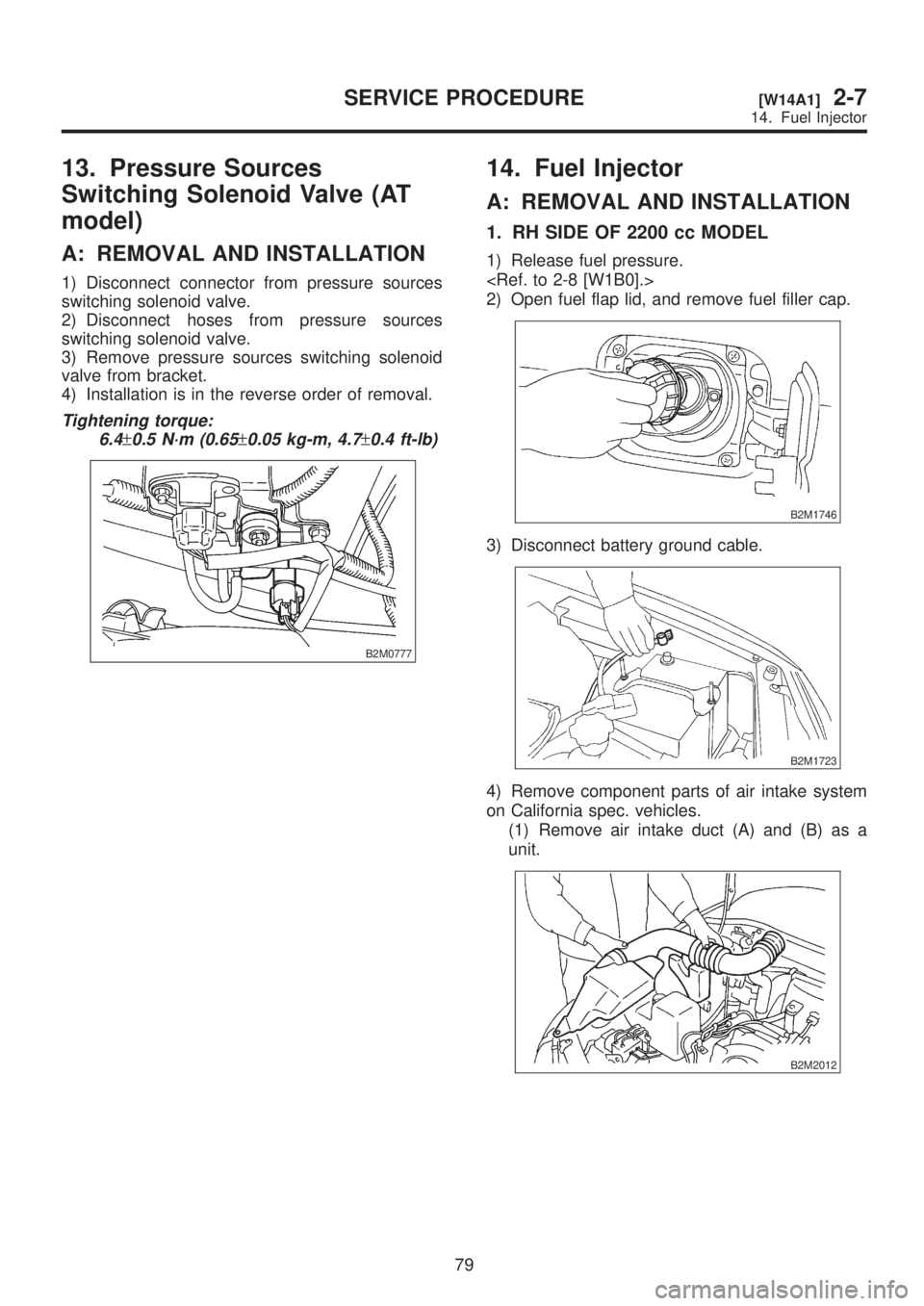
13. Pressure Sources
Switching Solenoid Valve (AT
model)
A: REMOVAL AND INSTALLATION
1) Disconnect connector from pressure sources
switching solenoid valve.
2) Disconnect hoses from pressure sources
switching solenoid valve.
3) Remove pressure sources switching solenoid
valve from bracket.
4) Installation is in the reverse order of removal.
Tightening torque:
6.4
±0.5 N´m (0.65±0.05 kg-m, 4.7±0.4 ft-lb)
B2M0777
14. Fuel Injector
A: REMOVAL AND INSTALLATION
1. RH SIDE OF 2200 cc MODEL
1) Release fuel pressure.
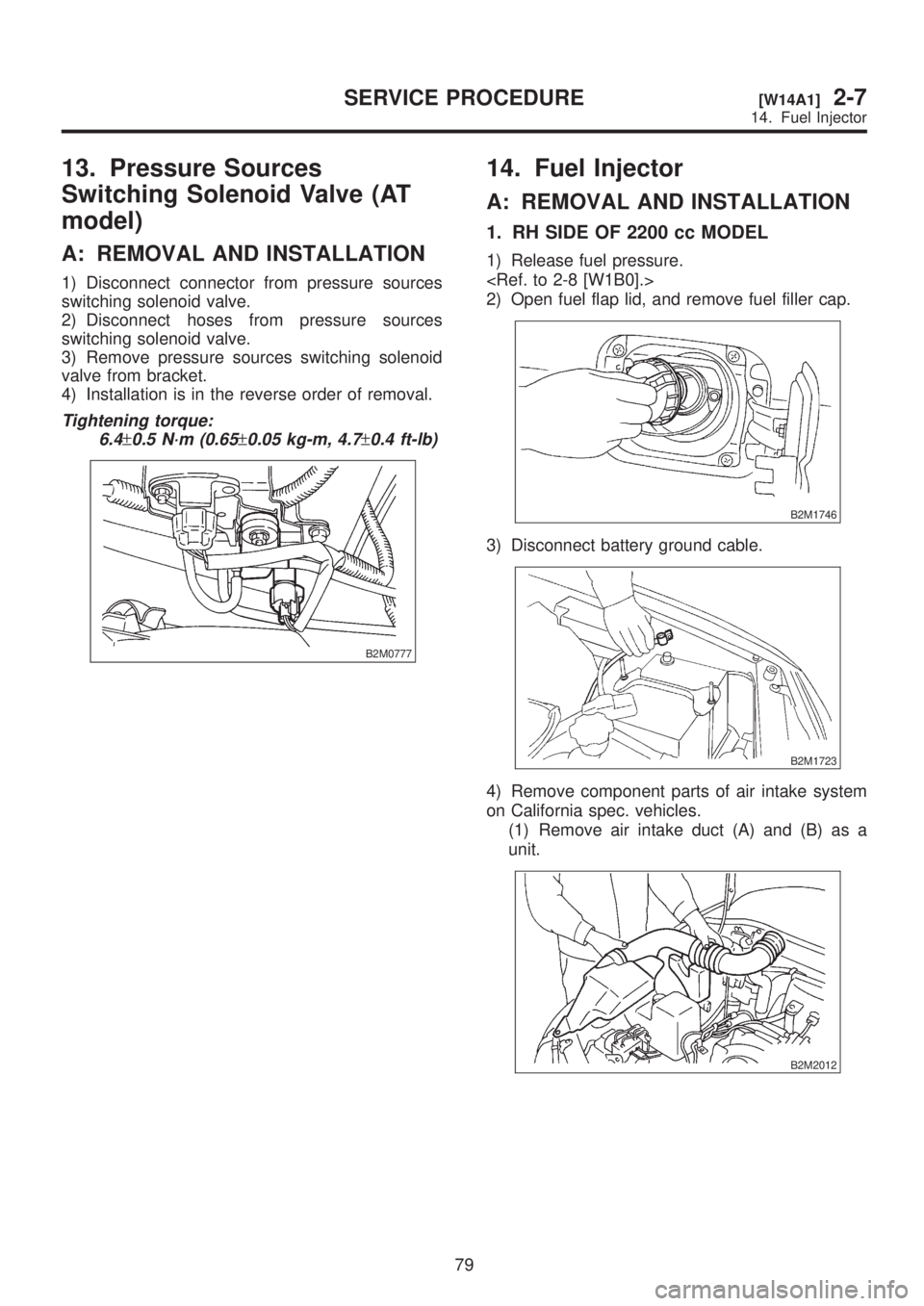
2) Open fuel flap lid, and remove fuel filler cap.
B2M1746
3) Disconnect battery ground cable.
B2M1723
4) Remove component parts of air intake system
on California spec. vehicles.
(1) Remove air intake duct (A) and (B) as a
unit.
B2M2012
79
[W14A1]2-7SERVICE PROCEDURE
14. Fuel Injector
Page 344 of 1456
13. Pressure Sources
Switching Solenoid Valve (AT
model)
A: REMOVAL AND INSTALLATION
1) Disconnect connector from pressure sources
switching solenoid valve.
2) Disconnect hoses from pressure sources
switching solenoid valve.
3) Remove pressure sources switching solenoid
valve from bracket.
4) Installation is in the reverse order of removal.
Tightening torque:
6.4
±0.5 N´m (0.65±0.05 kg-m, 4.7±0.4 ft-lb)
B2M0777
14. Fuel Injector
A: REMOVAL AND INSTALLATION
1. RH SIDE OF 2200 cc MODEL
1) Release fuel pressure.
2) Open fuel flap lid, and remove fuel filler cap.
B2M1746
3) Disconnect battery ground cable.
B2M1723
4) Remove component parts of air intake system
on California spec. vehicles.
(1) Remove air intake duct (A) and (B) as a
unit.
B2M2012
79
[W14A1]2-7SERVICE PROCEDURE
14. Fuel Injector
Page 347 of 1456
13) Installation is in the reverse order of removal.
CAUTION:
Replace O-rings with new ones.
Tightening torque:
3.4
±0.5 N´m (0.35±0.05 kg-m, 2.5±0.4 ft-lb)
B2M2366
2. LH SIDE OF 2200 cc MODEL
1) Release fuel pressure.
2) Open fuel flap lid, and remove fuel filler cap.
B2M1746
3) Disconnect battery ground cable.
B2M1723
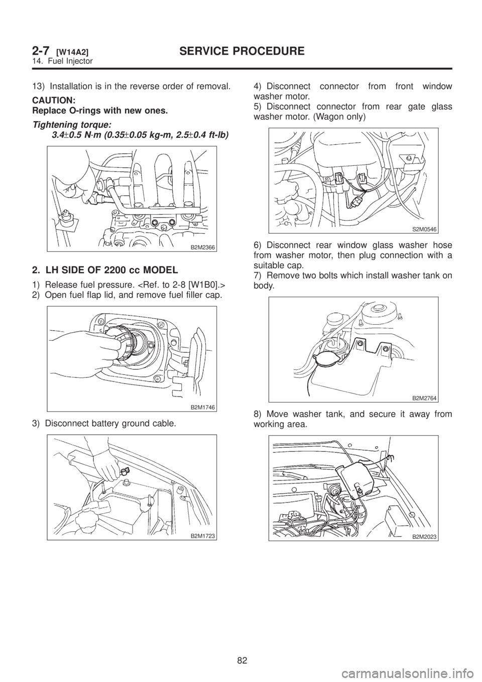
4) Disconnect connector from front window
washer motor.
5) Disconnect connector from rear gate glass
washer motor. (Wagon only)
S2M0546
6) Disconnect rear window glass washer hose
from washer motor, then plug connection with a
suitable cap.
7) Remove two bolts which install washer tank on
body.
B2M2764
8) Move washer tank, and secure it away from
working area.
B2M2023
82
2-7[W14A2]SERVICE PROCEDURE
14. Fuel Injector
Page 349 of 1456
2) Open fuel flap lid, and remove fuel filler cap.
B2M1746
3) Disconnect battery ground cable.
B2M1723
4) Disconnect connector from fuel injector.
G2M0398
5) Remove fuel injector from fuel pipe assembly.
G2M0431
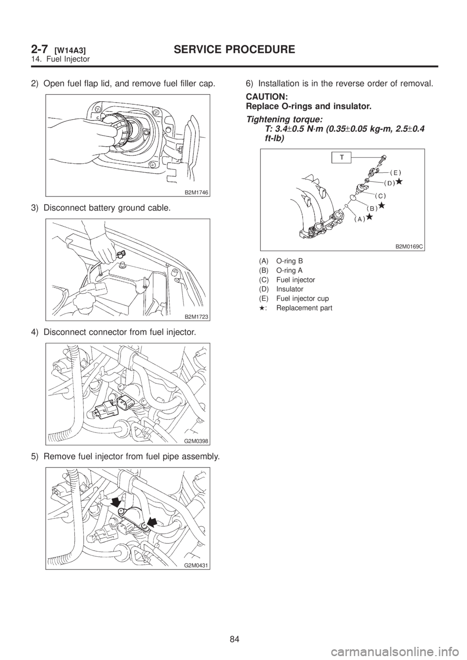
6) Installation is in the reverse order of removal.
CAUTION:
Replace O-rings and insulator.
Tightening torque:
T: 3.4
±0.5 N´m (0.35±0.05 kg-m, 2.5±0.4
ft-lb)
B2M0169C
(A) O-ring B
(B) O-ring A
(C) Fuel injector
(D) Insulator
(E) Fuel injector cup
H: Replacement part
84
2-7[W14A3]SERVICE PROCEDURE
14. Fuel Injector
Page 363 of 1456
1. Specifications
Fuel tankCapacity 60(15.9 US gal, 13.2 Imp gal)
Location Under rear seat
Fuel pumpType Impeller
Discharge pressure 299.1 kPa (3.05 kg/cm
2, 43.4 psi)
Discharge flowAWD: More than 80(21.1 US gal, 17.6 Imp gal)/h
[12 V at 300 kPa (3.06 kg/cm
2, 43.5 psi)]
Fuel filterCartridge type
2
2-8[S100]SPECIFICATIONS AND SERVICE DATA
1. Specifications
Page 367 of 1456
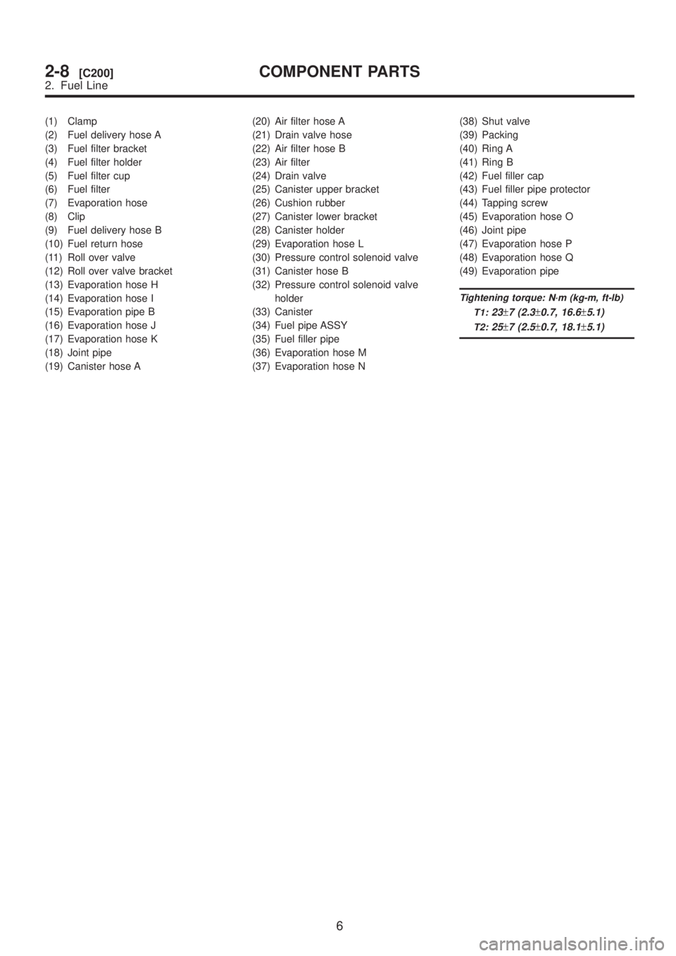
(1) Clamp
(2) Fuel delivery hose A
(3) Fuel filter bracket
(4) Fuel filter holder
(5) Fuel filter cup
(6) Fuel filter
(7) Evaporation hose
(8) Clip
(9) Fuel delivery hose B
(10) Fuel return hose
(11) Roll over valve
(12) Roll over valve bracket
(13) Evaporation hose H
(14) Evaporation hose I
(15) Evaporation pipe B
(16) Evaporation hose J
(17) Evaporation hose K
(18) Joint pipe
(19) Canister hose A(20) Air filter hose A
(21) Drain valve hose
(22) Air filter hose B
(23) Air filter
(24) Drain valve
(25) Canister upper bracket
(26) Cushion rubber
(27) Canister lower bracket
(28) Canister holder
(29) Evaporation hose L
(30) Pressure control solenoid valve
(31) Canister hose B
(32) Pressure control solenoid valve
holder
(33) Canister
(34) Fuel pipe ASSY
(35) Fuel filler pipe
(36) Evaporation hose M
(37) Evaporation hose N(38) Shut valve
(39) Packing
(40) Ring A
(41) Ring B
(42) Fuel filler cap
(43) Fuel filler pipe protector
(44) Tapping screw
(45) Evaporation hose O
(46) Joint pipe
(47) Evaporation hose P
(48) Evaporation hose Q
(49) Evaporation pipe
Tightening torque: N´m (kg-m, ft-lb)
T1:
23±7 (2.3±0.7, 16.6±5.1)
T2:25±7 (2.5±0.7, 18.1±5.1)
6
2-8[C200]COMPONENT PARTS
2. Fuel Line