1999 SUBARU LEGACY door open
[x] Cancel search: door openPage 785 of 1456

assembly, and tighten self-locking nut.
9) Connect stabilizer link to lateral link.
10) Install crossmember reinforcement lower to
crossmember (4 door model only).
11) Install ABS sensor clamps and parking brake
cable bracket.6. Full Wheel Cap
A: REMOVAL
Pry off the full wheel cap with a wheel cap remover
inserted between openings in the cap.
B4M0051
B: INSTALLATION
Align the valve hole in the wheel cap with the valve
on the wheel and secure the wheel cap by tapping
four points by hand.
38
4-2[W6A0]SERVICE PROCEDURE
6. Full Wheel Cap
Page 786 of 1456

assembly, and tighten self-locking nut.
9) Connect stabilizer link to lateral link.
10) Install crossmember reinforcement lower to
crossmember (4 door model only).
11) Install ABS sensor clamps and parking brake
cable bracket.6. Full Wheel Cap
A: REMOVAL
Pry off the full wheel cap with a wheel cap remover
inserted between openings in the cap.
B4M0051
B: INSTALLATION
Align the valve hole in the wheel cap with the valve
on the wheel and secure the wheel cap by tapping
four points by hand.
38
4-2[W6A0]SERVICE PROCEDURE
6. Full Wheel Cap
Page 999 of 1456
10. Performance Test
A: INSPECTION
1. VEHICLE SET UP
In order to obtain meaningful test results, the
vehicle must be set up to meet the following con-
ditions.
IVehicle in shade
INo wind
IAll vehicle doors closed
IFront windows opened
IHood opened
IEngine speed set at 1,500 rpm.
IA/C ON
ITemperature control lever Ð Maximum cold
IAir source Ð Recirculation
IBlower speed Ð 4th position (High)
IOperate A/C for 10 minutes (Minimum) before
taking measurement.
2. MEASUREMENTS
After 10 minutes (Minimum) of A/C operation and
using accurate test equipment, take the following
measurements (in order).
1) Evaporator intake air temperature at recircula-
tion door.
2) Evaporator discharge air temperature at center
grill.
3) Condenser (Ambient) intake air temperature
measured 0.9 m (3 ft) in front and in line with the
center of the condenser.
4) Suction (Low) side pressure
5) Discharge (High) side pressure
NOTE:
If only one thermometer is available; 1)take the
ambient measurement first; then 2)the intake air;
and 3)discharge air temperature.
22
4-7[W10A1]SERVICE PROCEDURE
10. Performance Test
Page 1114 of 1456
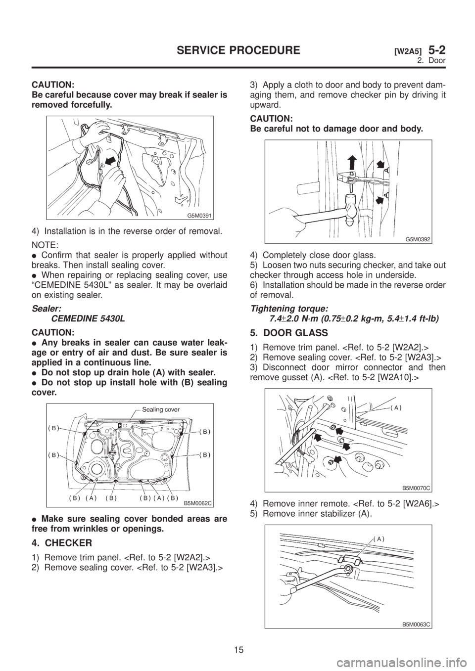
CAUTION:
Be careful because cover may break if sealer is
removed forcefully.
G5M0391
4) Installation is in the reverse order of removal.
NOTE:
IConfirm that sealer is properly applied without
breaks. Then install sealing cover.
IWhen repairing or replacing sealing cover, use
ªCEMEDINE 5430Lº as sealer. It may be overlaid
on existing sealer.
Sealer:
CEMEDINE 5430L
CAUTION:
IAny breaks in sealer can cause water leak-
age or entry of air and dust. Be sure sealer is
applied in a continuous line.
IDo not stop up drain hole (A) with sealer.
IDo not stop up install hole with (B) sealing
cover.
B5M0062C
IMake sure sealing cover bonded areas are
free from wrinkles or openings.
4. CHECKER
1) Remove trim panel.
2) Remove sealing cover.
aging them, and remove checker pin by driving it
upward.
CAUTION:
Be careful not to damage door and body.
G5M0392
4) Completely close door glass.
5) Loosen two nuts securing checker, and take out
checker through access hole in underside.
6) Installation should be made in the reverse order
of removal.
Tightening torque:
7.4
±2.0 N´m (0.75±0.2 kg-m, 5.4±1.4 ft-lb)
5. DOOR GLASS
1) Remove trim panel.
2) Remove sealing cover.
3) Disconnect door mirror connector and then
remove gusset (A).
B5M0070C
4) Remove inner remote.
5) Remove inner stabilizer (A).
B5M0063C
15
[W2A5]5-2SERVICE PROCEDURE
2. Door
Page 1117 of 1456
![SUBARU LEGACY 1999 Service Repair Manual 10. GUSSET
1) Be sure window is all the way down.
2) Remove trim panel. <Ref. to 5-2 [W2A2].>
3) Remove door rearview mirror.
4) Remove sealing cover. <Ref. to 5-2 [W2A3].>
5) Remove bolts and nuts wh](/manual-img/17/57435/w960_57435-1116.png "SUBARU LEGACY 1999 Service Repair Manual 10. GUSSET
1) Be sure window is all the way down.
2) Remove trim panel. <Ref. to 5-2 [W2A2].>
3) Remove door rearview mirror.
4) Remove sealing cover. <Ref. to 5-2 [W2A3].>
5) Remove bolts and nuts wh")
10. GUSSET
1) Be sure window is all the way down.
2) Remove trim panel.
3) Remove door rearview mirror.
4) Remove sealing cover.
5) Remove bolts and nuts which secure gusset
(A).
6) Lift out gusset (A).
B5M0070D
7) Installation is in the reverse order of removal.
11. REAR DOOR CATCHER
1) Open the rear door.
2) Using TORXTBIT (Tamper resistant type),
remove rear door catcher.
B5M0467A
3) Installation is in the reverse order of removal.
Tightening torque:
37
±10 N´m (3.8±1.0 kg-m, 27.5±7.2 ft-lb)
B: ADJUSTMENT
1. DOOR ASSEMBLY
1) Using ST, loosen bolts securing upper and
lower hinges to body, and adjust fore-and-aft and
vertical alignment of door.
ST 925610000 DOOR HINGE WRENCH
2) Loosen mounting screws approximately one
rotation. Adjust striker (A) position by lightly tap-
ping with hammer. (To adjust, utilize the shape of
striker nut plate support (B).)
CAUTION:
IUse cloth to prevent damaging body or other
parts.
IDo not directly tap striker plastic portion.
IDo not apply impact on spot-welded striker
nut plate.
Hinge tightening torque (body side):
29
±5 N´m (3.0±0.5 kg-m, 21.7±3.6 ft-lb)
Striker tightening torque:
14
±4 N´m (1.4±0.4 kg-m, 10.1±2.9 ft-lb)
B5M0071C
18
5-2[W2A10]SERVICE PROCEDURE
2. Door
Page 1133 of 1456
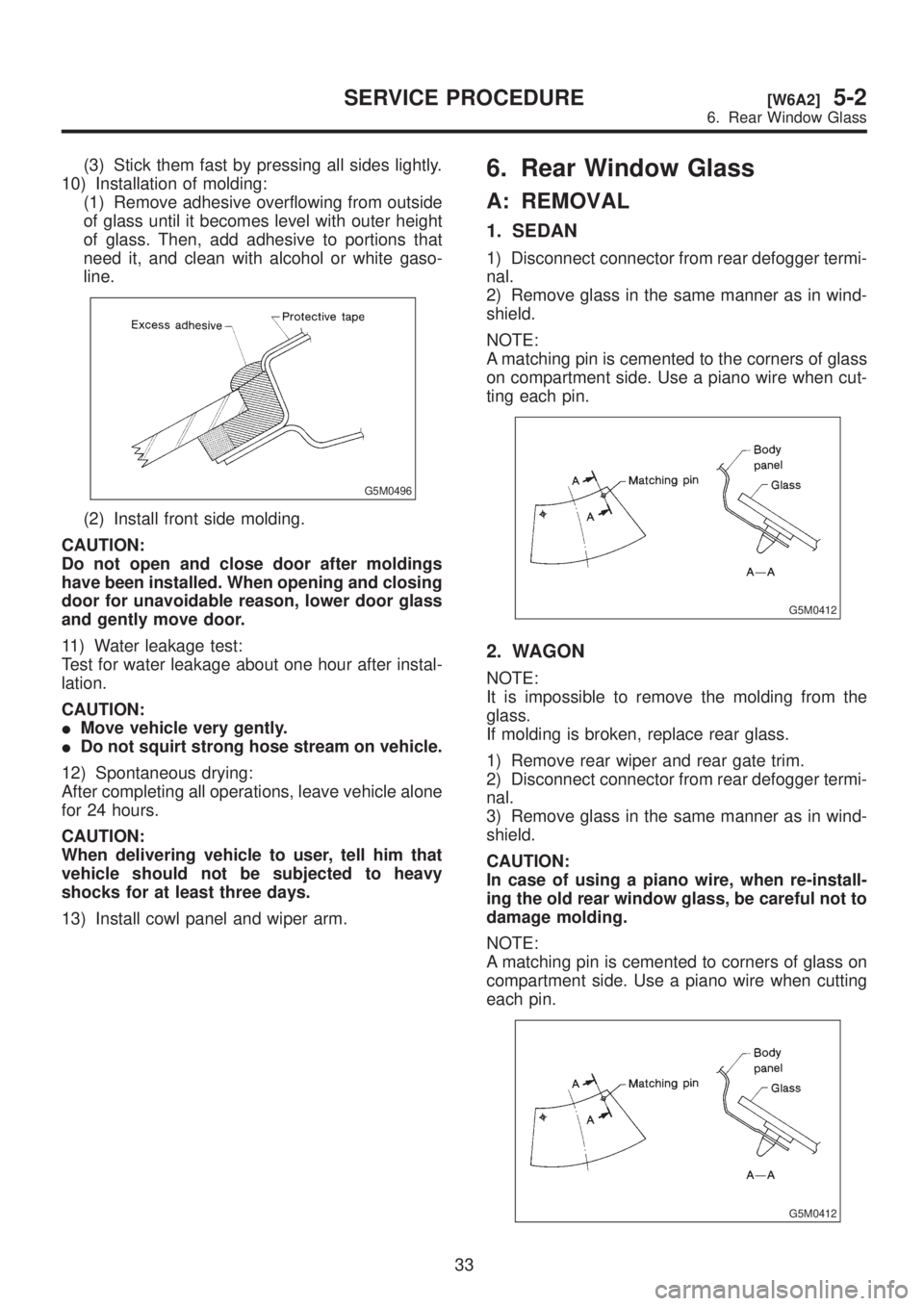
(3) Stick them fast by pressing all sides lightly.
10) Installation of molding:
(1) Remove adhesive overflowing from outside
of glass until it becomes level with outer height
of glass. Then, add adhesive to portions that
need it, and clean with alcohol or white gaso-
line.
G5M0496
(2) Install front side molding.
CAUTION:
Do not open and close door after moldings
have been installed. When opening and closing
door for unavoidable reason, lower door glass
and gently move door.
11) Water leakage test:
Test for water leakage about one hour after instal-
lation.
CAUTION:
IMove vehicle very gently.
IDo not squirt strong hose stream on vehicle.
12) Spontaneous drying:
After completing all operations, leave vehicle alone
for 24 hours.
CAUTION:
When delivering vehicle to user, tell him that
vehicle should not be subjected to heavy
shocks for at least three days.
13) Install cowl panel and wiper arm.
6. Rear Window Glass
A: REMOVAL
1. SEDAN
1) Disconnect connector from rear defogger termi-
nal.
2) Remove glass in the same manner as in wind-
shield.
NOTE:
A matching pin is cemented to the corners of glass
on compartment side. Use a piano wire when cut-
ting each pin.
G5M0412
2. WAGON
NOTE:
It is impossible to remove the molding from the
glass.
If molding is broken, replace rear glass.
1) Remove rear wiper and rear gate trim.
2) Disconnect connector from rear defogger termi-
nal.
3) Remove glass in the same manner as in wind-
shield.
CAUTION:
In case of using a piano wire, when re-install-
ing the old rear window glass, be careful not to
damage molding.
NOTE:
A matching pin is cemented to corners of glass on
compartment side. Use a piano wire when cutting
each pin.
G5M0412
33
[W6A2]5-2SERVICE PROCEDURE
6. Rear Window Glass
Page 1134 of 1456
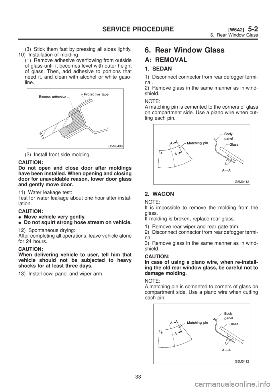
(3) Stick them fast by pressing all sides lightly.
10) Installation of molding:
(1) Remove adhesive overflowing from outside
of glass until it becomes level with outer height
of glass. Then, add adhesive to portions that
need it, and clean with alcohol or white gaso-
line.
G5M0496
(2) Install front side molding.
CAUTION:
Do not open and close door after moldings
have been installed. When opening and closing
door for unavoidable reason, lower door glass
and gently move door.
11) Water leakage test:
Test for water leakage about one hour after instal-
lation.
CAUTION:
IMove vehicle very gently.
IDo not squirt strong hose stream on vehicle.
12) Spontaneous drying:
After completing all operations, leave vehicle alone
for 24 hours.
CAUTION:
When delivering vehicle to user, tell him that
vehicle should not be subjected to heavy
shocks for at least three days.
13) Install cowl panel and wiper arm.
6. Rear Window Glass
A: REMOVAL
1. SEDAN
1) Disconnect connector from rear defogger termi-
nal.
2) Remove glass in the same manner as in wind-
shield.
NOTE:
A matching pin is cemented to the corners of glass
on compartment side. Use a piano wire when cut-
ting each pin.
G5M0412
2. WAGON
NOTE:
It is impossible to remove the molding from the
glass.
If molding is broken, replace rear glass.
1) Remove rear wiper and rear gate trim.
2) Disconnect connector from rear defogger termi-
nal.
3) Remove glass in the same manner as in wind-
shield.
CAUTION:
In case of using a piano wire, when re-install-
ing the old rear window glass, be careful not to
damage molding.
NOTE:
A matching pin is cemented to corners of glass on
compartment side. Use a piano wire when cutting
each pin.
G5M0412
33
[W6A2]5-2SERVICE PROCEDURE
6. Rear Window Glass
Page 1137 of 1456
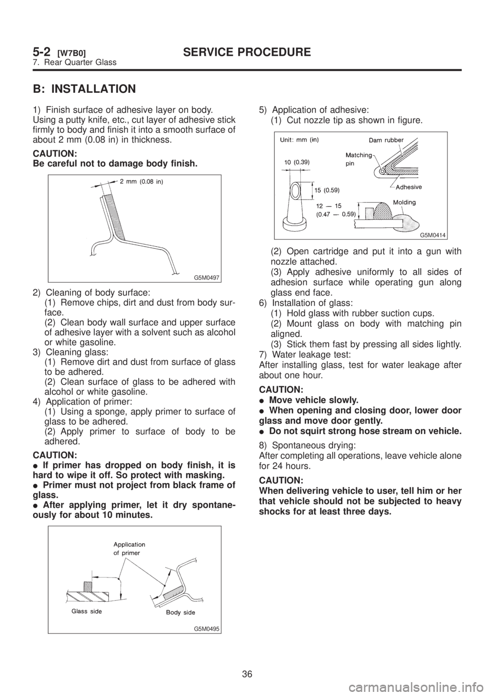
B: INSTALLATION
1) Finish surface of adhesive layer on body.
Using a putty knife, etc., cut layer of adhesive stick
firmly to body and finish it into a smooth surface of
about 2 mm (0.08 in) in thickness.
CAUTION:
Be careful not to damage body finish.
G5M0497
2) Cleaning of body surface:
(1) Remove chips, dirt and dust from body sur-
face.
(2) Clean body wall surface and upper surface
of adhesive layer with a solvent such as alcohol
or white gasoline.
3) Cleaning glass:
(1) Remove dirt and dust from surface of glass
to be adhered.
(2) Clean surface of glass to be adhered with
alcohol or white gasoline.
4) Application of primer:
(1) Using a sponge, apply primer to surface of
glass to be adhered.
(2) Apply primer to surface of body to be
adhered.
CAUTION:
IIf primer has dropped on body finish, it is
hard to wipe it off. So protect with masking.
IPrimer must not project from black frame of
glass.
IAfter applying primer, let it dry spontane-
ously for about 10 minutes.
G5M0495
5) Application of adhesive:
(1) Cut nozzle tip as shown in figure.
G5M0414
(2) Open cartridge and put it into a gun with
nozzle attached.
(3) Apply adhesive uniformly to all sides of
adhesion surface while operating gun along
glass end face.
6) Installation of glass:
(1) Hold glass with rubber suction cups.
(2) Mount glass on body with matching pin
aligned.
(3) Stick them fast by pressing all sides lightly.
7) Water leakage test:
After installing glass, test for water leakage after
about one hour.
CAUTION:
IMove vehicle slowly.
IWhen opening and closing door, lower door
glass and move door gently.
IDo not squirt strong hose stream on vehicle.
8) Spontaneous drying:
After completing all operations, leave vehicle alone
for 24 hours.
CAUTION:
When delivering vehicle to user, tell him or her
that vehicle should not be subjected to heavy
shocks for at least three days.
36
5-2[W7B0]SERVICE PROCEDURE
7. Rear Quarter Glass