Page 119 of 1456
2. CYLINDER BLOCK
B2M2407A
(1) Crankshaft bearing
(2) Crankshaft
(3) Cylinder block(4) Rear oil sealTightening torque: N´m (kg-m, ft-lb)
T1:
25±2 (2.5±0.2, 18.1±1.4)
T2:47±3 (4.8±0.3, 34.7±2.2)
1) Install ST to cylinder block, then install crank-
shaft bearings.
ST 499817000 ENGINE STAND
CAUTION:
Remove oil in the mating surface of bearing
and cylinder block before installation. Also
apply a coat of engine oil to crankshaft pins.
2) Position crankshaft on the #2 and #4 cylinder
block.3) Apply fluid packing to the mating surface of #1
and #3 cylinder block, and position it on #2 and #4
cylinder block.
Fluid packing:
THREE BOND 1215 or equivalent
CAUTION:
Do not allow fluid packing to jut into O-ring
grooves, oil passages, bearing grooves, etc.
G2M0185
65
[W6D2]2-3aSERVICE PROCEDURE
6. Cylinder Block
Page 120 of 1456
4) Temporarily tighten 10 mm cylinder block con-
necting bolts in alphabetical sequence shown in
figure.
B2M0088D
5) Tighten 10 mm cylinder block connecting bolts
in alphabetical sequence.
Tightening torque:
47
±3 N´m (4.8±0.3 kg-m, 34.7±2.2 ft-lb)
B2M0088D
6) Tighten 8 mm and 6 mm cylinder block connect-
ing bolts in alphabetical sequence shown in figure.
Tightening torque:
(A) Ð (G): 25
±2 N´m (2.5±0.2 kg-m,
18.1
±1.4 ft-lb)
(H): 6.4 N´m (0.65 kg-m, 4.7 ft-lb)
B2M0089F
7) Install rear oil seal using ST1 and ST2.
ST1 499597100 OIL SEAL GUIDE
ST2 499587200 OIL SEAL INSTALLER
G2M0186
66
2-3a[W6D2]SERVICE PROCEDURE
6. Cylinder Block
Page 133 of 1456

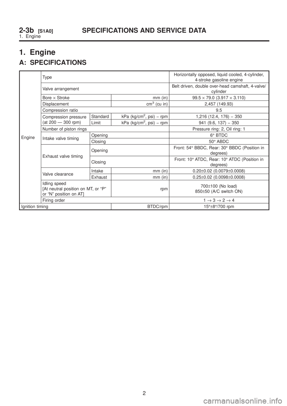
1. Engine
A: SPECIFICATIONS
EngineTypeHorizontally opposed, liquid cooled, 4-cylinder,
4-stroke gasoline engine
Valve arrangementBelt driven, double over-head camshaft, 4-valve/
cylinder
Bore´Stroke mm (in) 99.5´79.0 (3.917´3.110)
Displacement cm
3(cu in) 2,457 (149.93)
Compression ratio 9.5
Compression pressure
(at 200 Ð 300 rpm)Standard kPa (kg/cm
2, psi) þ rpm 1,216 (12.4, 176) þ 350
Limit kPa (kg/cm2, psi) þ rpm 941 (9.6, 137) þ 350
Number of piston rings Pressure ring: 2, Oil ring: 1
Intake valve timingOpening 6É BTDC
Closing 50É ABDC
Exhaust valve timingOpeningFront: 54É BBDC, Rear: 30É BBDC (Position in
degrees)
ClosingFront: 10É ATDC, Rear: 10É ATDC (Position in
degrees)
Valve clearanceIntake mm (in) 0.20±0.02 (0.0079±0.0008)
Exhaust mm (in) 0.25±0.02 (0.0098±0.0008)
Idling speed
[At neutral position on MT, or ªPº
or ªNº position on AT]rpm700±100 (No load)
850±50 (A/C switch ON)
Firing order 1®3®2®4
Ignition timing BTDC/rpm 15ɱ8É/700 rpm
2
2-3b[S1A0]SPECIFICATIONS AND SERVICE DATA
1. Engine
Page 134 of 1456

B: SERVICE DATA
NOTE:
STD: Standard, I.D.: Inner Diameter, O.D.: Outer Diameter, OS: Oversize, US: Undersize
Belt ten-
sion
adjusterProtrusion of adjuster rod 5.2 Ð 6.2 mm (0.205 Ð 0.244 in)
Belt ten-
sionerSpacer O.D. 17.955 Ð 17.975 mm (0.7069 Ð 0.7077 in)
Tensioner bush I.D. 18.00 Ð 18.08 mm (0.7087 Ð 0.7118 in)
Clearance between spacer and
bushSTD 0.025 Ð 0.125 mm (0.0010 Ð 0.0049 in)
Limit 0.175 mm (0.0069 in)
Side clearance of spacerSTD 0.2 Ð 0.55 mm (0.0079 Ð 0.0217 in)
Limit 0.81 mm (0.0319 in)
CamshaftBend limit 0.020 mm (0.0008 in)
Thrust clearanceSTD 0.040 Ð 0.080 mm (0.0016 Ð 0.0031 in)
Limit 0.10 mm (0.0039 in)
Cam lobe heightIntakeSTD 42.20 Ð 42.30 mm (1.6614 Ð 1.6654 in)
Limit 42.04 mm (1.6551 in)
ExhaustSTDFront: 42.50 Ð 42.60 mm
Rear: 41.40 Ð 41.50 mm(1.6732 Ð 1.6772 in) (1.6299
Ð 1.6339 in)
LimitFront: 42.34 mm Rear: 41.24
mm(1.6669 in) (1.6236 in)
Camshaft journal O.D.Front 31.946 Ð 31.963 mm (1.2577 Ð 1.2584 in)
Center 27.946 Ð 27.963 mm (1.1002 Ð 1.1009 in)
Rear 27.946 Ð 27.963 mm (1.1002 Ð 1.1009 in)
Camshaft journal hole I.D.Front 32.000 Ð 32.018 mm (1.2598 Ð 1.2605 in)
Center 28.000 Ð 28.018 mm (1.1024 Ð 1.1031 in)
Rear 28.000 Ð 28.018 mm (1.1024 Ð 1.1031 in)
Oil clearanceSTD 0.037 Ð 0.072 mm (0.0015 Ð 0.0028 in)
Limit 0.10 mm (0.0039 in)
Cylinder
headSurface warpage limit 0.05 mm (0.0020 in)
Surface grinding limit 0.3 mm (0.012 in)
Standard height 127.5 mm (5.02 in)
Valve seatRefacing angle 90É
Contacting widthIntakeSTD 1.0 mm (0.039 in)
Limit 1.7 mm (0.067 in)
ExhaustSTD 1.5 mm (0.059 in)
Limit 2.2 mm (0.087 in)
Valve guideInner diameter 6.000 Ð 6.015 mm (0.2362 Ð 0.2368 in)
Protrusion above head 12.0 Ð 12.4 mm (0.472 Ð 0.488 in)
ValveHead edge thicknessIntakeSTD 1.2 mm (0.047 in)
Limit 0.8 mm (0.031 in)
ExhaustSTD 1.5 mm (0.059 in)
Limit 0.8 mm (0.031 in)
Stem diameterIntake 5.950 Ð 5.965 mm (0.2343 Ð 0.2348 in)
Exhaust 5.950 Ð 5.965 mm (0.2343 Ð 0.2348 in)
Stem oil clearanceSTDIntake 0.035 Ð 0.062 mm (0.0014 Ð 0.0024 in)
Exhaust 0.040 Ð 0.067 mm (0.0016 Ð 0.0026 in)
Limit Ð 0.15 mm (0.0059 in)
Overall lengthIntake 105.9 mm (4.169 in)
Exhaust 106.2 mm (4.181 in)
3
[S1B0]2-3bSPECIFICATIONS AND SERVICE DATA
1. Engine
Page 140 of 1456

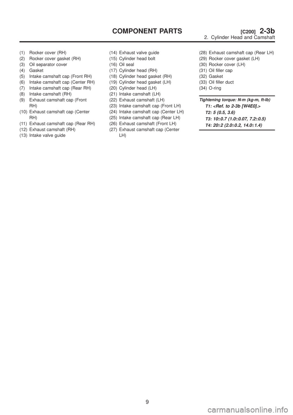
(1) Rocker cover (RH)
(2) Rocker cover gasket (RH)
(3) Oil separator cover
(4) Gasket
(5) Intake camshaft cap (Front RH)
(6) Intake camshaft cap (Center RH)
(7) Intake camshaft cap (Rear RH)
(8) Intake camshaft (RH)
(9) Exhaust camshaft cap (Front
RH)
(10) Exhaust camshaft cap (Center
RH)
(11) Exhaust camshaft cap (Rear RH)
(12) Exhaust camshaft (RH)
(13) Intake valve guide(14) Exhaust valve guide
(15) Cylinder head bolt
(16) Oil seal
(17) Cylinder head (RH)
(18) Cylinder head gasket (RH)
(19) Cylinder head gasket (LH)
(20) Cylinder head (LH)
(21) Intake camshaft (LH)
(22) Exhaust camshaft (LH)
(23) Intake camshaft cap (Front LH)
(24) Intake camshaft cap (Center LH)
(25) Intake camshaft cap (Rear LH)
(26) Exhaust camshaft (Front LH)
(27) Exhaust camshaft cap (Center
LH)(28) Exhaust camshaft cap (Rear LH)
(29) Rocker cover gasket (LH)
(30) Rocker cover (LH)
(31) Oil filler cap
(32) Gasket
(33) Oil filler duct
(34) O-ring
Tightening torque: N´m (kg-m, ft-lb)
T1:
T2:5 (0.5, 3.6)
T3:10±0.7 (1.0±0.07, 7.2±0.5)
T4:20±2 (2.0±0.2, 14.0±1.4)
9
[C200]2-3bCOMPONENT PARTS
2. Cylinder Head and Camshaft
Page 142 of 1456
4. Cylinder Block
B2M1766A
(1) Oil pressure switch
(2) Cylinder block (RH)
(3) Service hole plug
(4) Gasket
(5) Oil separator cover
(6) Water by-pass pipe
(7) Oil pump
(8) Front oil seal
(9) Rear oil seal
(10) O-ring
(11) Service hole cover(12) Cylinder block (LH)
(13) Water pump
(14) Baffle plate
(15) Oil filter connector
(16) Oil strainer
(17) Gasket
(18) Oil pan
(19) Drain plug
(20) Metal gasket
(21) Oil level gauge guideTightening torque: N´m (kg-m, ft-lb)
T1:
5 (0.5, 3.6)
T2:6.4 (0.65, 4.7)
T3:10 (1.0, 7)
T4:25±2 (2.5±0.2, 18.1±1.4)
T5:47±3 (4.8±0.3, 34.7±2.2)
T6:69±7 (7.0±0.7, 50.6±5.1)
T7:First 12±2 (1.2±0.2, 8.7±1.4)
Second 12
±2 (1.2±0.2,
8.7
±1.4)
11
[C400]2-3bCOMPONENT PARTS
4. Cylinder Block
Page 162 of 1456

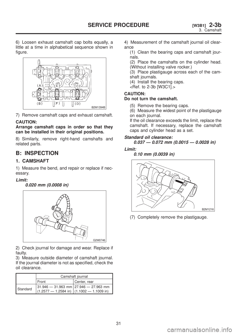
6) Loosen exhaust camshaft cap bolts equally, a
little at a time in alphabetical sequence shown in
figure.
B2M1394B
7) Remove camshaft caps and exhaust camshaft.
CAUTION:
Arrange camshaft caps in order so that they
can be installed in their original positions.
8) Similarly, remove right-hand camshafts and
related parts.
B: INSPECTION
1. CAMSHAFT
1) Measure the bend, and repair or replace if nec-
essary.
Limit:
0.020 mm (0.0008 in)
G2M0746
2) Check journal for damage and wear. Replace if
faulty.
3) Measure outside diameter of camshaft journal.
If the journal diameter is not as specified, check the
oil clearance.
Camshaft journal
Front Center, rear
Standard31.946 Ð 31.963 mm
(1.2577 Ð 1.2584 in)27.946 Ð 27.963 mm
(1.1002 Ð 1.1009 in)
4) Measurement of the camshaft journal oil clear-
ance
(1) Clean the bearing caps and camshaft jour-
nals.
(2) Place the camshafts on the cylinder head.
(Without installing valve rocker.)
(3) Place plastigauge across each of the cam-
shaft journals.
(4) Install the bearing caps.
CAUTION:
Do not turn the camshaft.
(5) Remove the bearing caps.
(6) Measure the widest point of the plastigauge
on each journal.
If the oil clearance exceeds the limit, replace the
camshaft. If necessary, replace the camshaft
caps and cylinder head as a set.
Standard oil clearance:
0.037 Ð 0.072 mm (0.0015 Ð 0.0028 in)
Limit:
0.10 mm (0.0039 in)
B2M1216
(7) Completely remove the plastigauge.
31
[W3B1]2-3bSERVICE PROCEDURE
3. Camshaft
Page 163 of 1456
5) Check cam face condition; remove minor faults
by grinding with oil stone. Measure the cam height
H; replace if the limit has been exceeded.
Cam height: H
Standard:
Intake:
42.20 Ð 42.30 mm (1.6614 Ð 1.6654 in)
Exhaust:
Front: 42.50 Ð 42.60 mm (1.6732 Ð
1.6772 in)
Rear: 41.40 Ð 41.50 mm (1.6299 Ð 1.6339
in)
Limit:
Intake:
42.04 mm (1.6551 in)
Exhaust:
Front: 42.34 mm (1.6669 in)
Rear: 41.24 mm (1.6236 in)
Cam base circle diameter A:
28.0 mm (1.102 in)
B2M1209A
6) Measure the thrust clearance of camshaft with
dial gauge. If the clearance exceeds the limit,
replace caps and cylinder head as a set. If neces-
sary replace camshaft.
Standard:
0.040 Ð 0.080 mm (0.0016 Ð 0.0031 in)
Limit:
0.1 mm (0.004 in)
B2M1217
32
2-3b[W3B1]SERVICE PROCEDURE
3. Camshaft