1999 SUBARU LEGACY tire pressure
[x] Cancel search: tire pressurePage 863 of 1456
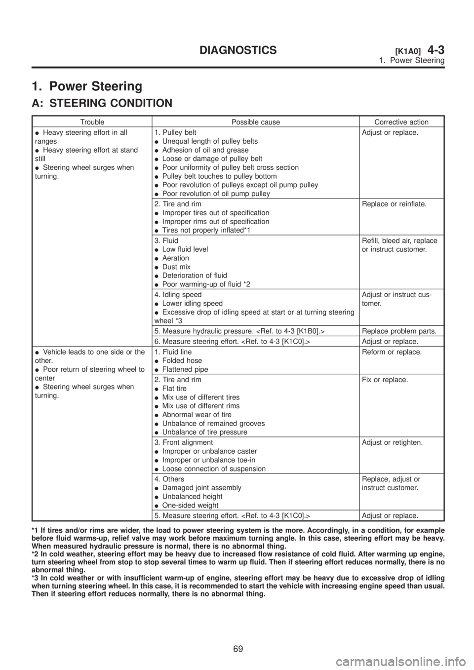
1. Power Steering
A: STEERING CONDITION
Trouble Possible cause Corrective action
IHeavy steering effort in all
ranges
IHeavy steering effort at stand
still
ISteering wheel surges when
turning.1. Pulley belt
IUnequal length of pulley belts
IAdhesion of oil and grease
ILoose or damage of pulley belt
IPoor uniformity of pulley belt cross section
IPulley belt touches to pulley bottom
IPoor revolution of pulleys except oil pump pulley
IPoor revolution of oil pump pulleyAdjust or replace.
2. Tire and rim
IImproper tires out of specification
IImproper rims out of specification
ITires not properly inflated*1Replace or reinflate.
3. Fluid
ILow fluid level
IAeration
IDust mix
IDeterioration of fluid
IPoor warming-up of fluid *2Refill, bleed air, replace
or instruct customer.
4. Idling speed
ILower idling speed
IExcessive drop of idling speed at start or at turning steering
wheel *3Adjust or instruct cus-
tomer.
5. Measure hydraulic pressure.
6. Measure steering effort.
IVehicle leads to one side or the
other.
IPoor return of steering wheel to
center
ISteering wheel surges when
turning.1. Fluid line
IFolded hose
IFlattened pipeReform or replace.
2. Tire and rim
IFlat tire
IMix use of different tires
IMix use of different rims
IAbnormal wear of tire
IUnbalance of remained grooves
IUnbalance of tire pressureFix or replace.
3. Front alignment
IImproper or unbalance caster
IImproper or unbalance toe-in
ILoose connection of suspensionAdjust or retighten.
4. Others
IDamaged joint assembly
IUnbalanced height
IOne-sided weightReplace, adjust or
instruct customer.
5. Measure steering effort.
*1 If tires and/or rims are wider, the load to power steering system is the more. Accordingly, in a condition, for example
before fluid warms-up, relief valve may work before maximum turning angle. In this case, steering effort may be heavy.
When measured hydraulic pressure is normal, there is no abnormal thing.
*2 In cold weather, steering effort may be heavy due to increased flow resistance of cold fluid. After warming up engine,
turn steering wheel from stop to stop several times to warm up fluid. Then if steering effort reduces normally, there is no
abnormal thing.
*3 In cold weather or with insufficient warm-up of engine, steering effort may be heavy due to excessive drop of idling
when turning steering wheel. In this case, it is recommended to start the vehicle with increasing engine speed than usual.
Then if steering effort reduces normally, there is no abnormal thing.
69
[K1A0]4-3DIAGNOSTICS
1. Power Steering
Page 900 of 1456
4) Raise caliper body and move it toward vehicle
center to separate it from support.
5) Remove support from back plate.
NOTE:
Remove support only when replacing it or the rotor.
It need not be removed when servicing caliper
body assembly.
6) Clean mud and foreign particles from caliper
body assembly and support.
CAUTION:
Be careful not to allow foreign particles to enter
inlet (at brake hose connector).
C: DISASSEMBLY
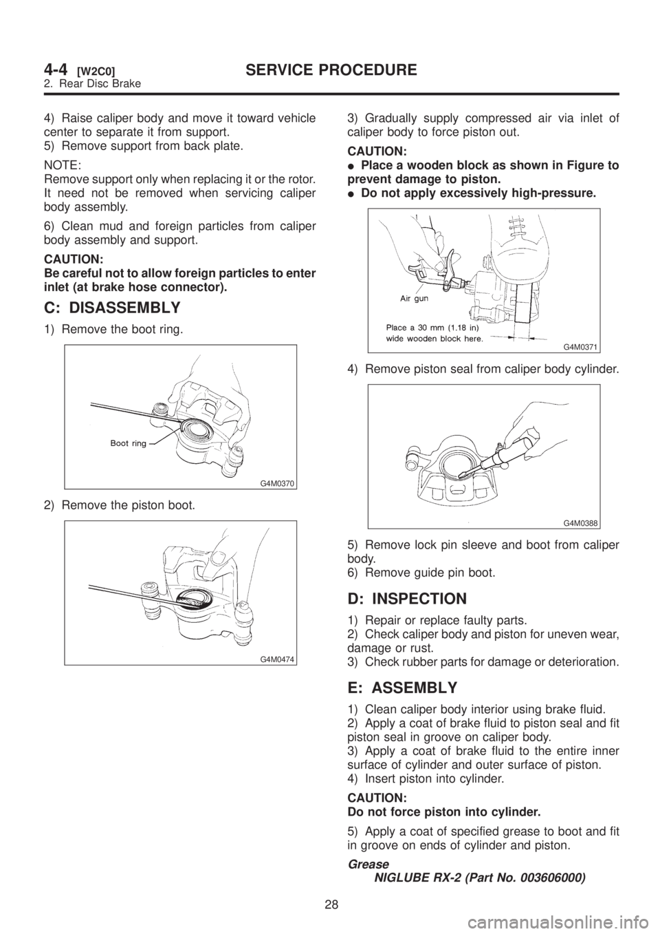
1) Remove the boot ring.
G4M0370
2) Remove the piston boot.
G4M0474
3) Gradually supply compressed air via inlet of
caliper body to force piston out.
CAUTION:
IPlace a wooden block as shown in Figure to
prevent damage to piston.
IDo not apply excessively high-pressure.
G4M0371
4) Remove piston seal from caliper body cylinder.
G4M0388
5) Remove lock pin sleeve and boot from caliper
body.
6) Remove guide pin boot.
D: INSPECTION
1) Repair or replace faulty parts.
2) Check caliper body and piston for uneven wear,
damage or rust.
3) Check rubber parts for damage or deterioration.
E: ASSEMBLY
1) Clean caliper body interior using brake fluid.
2) Apply a coat of brake fluid to piston seal and fit
piston seal in groove on caliper body.
3) Apply a coat of brake fluid to the entire inner
surface of cylinder and outer surface of piston.
4) Insert piston into cylinder.
CAUTION:
Do not force piston into cylinder.
5) Apply a coat of specified grease to boot and fit
in groove on ends of cylinder and piston.
Grease
NIGLUBE RX-2 (Part No. 003606000)
28
4-4[W2C0]SERVICE PROCEDURE
2. Rear Disc Brake
Page 943 of 1456
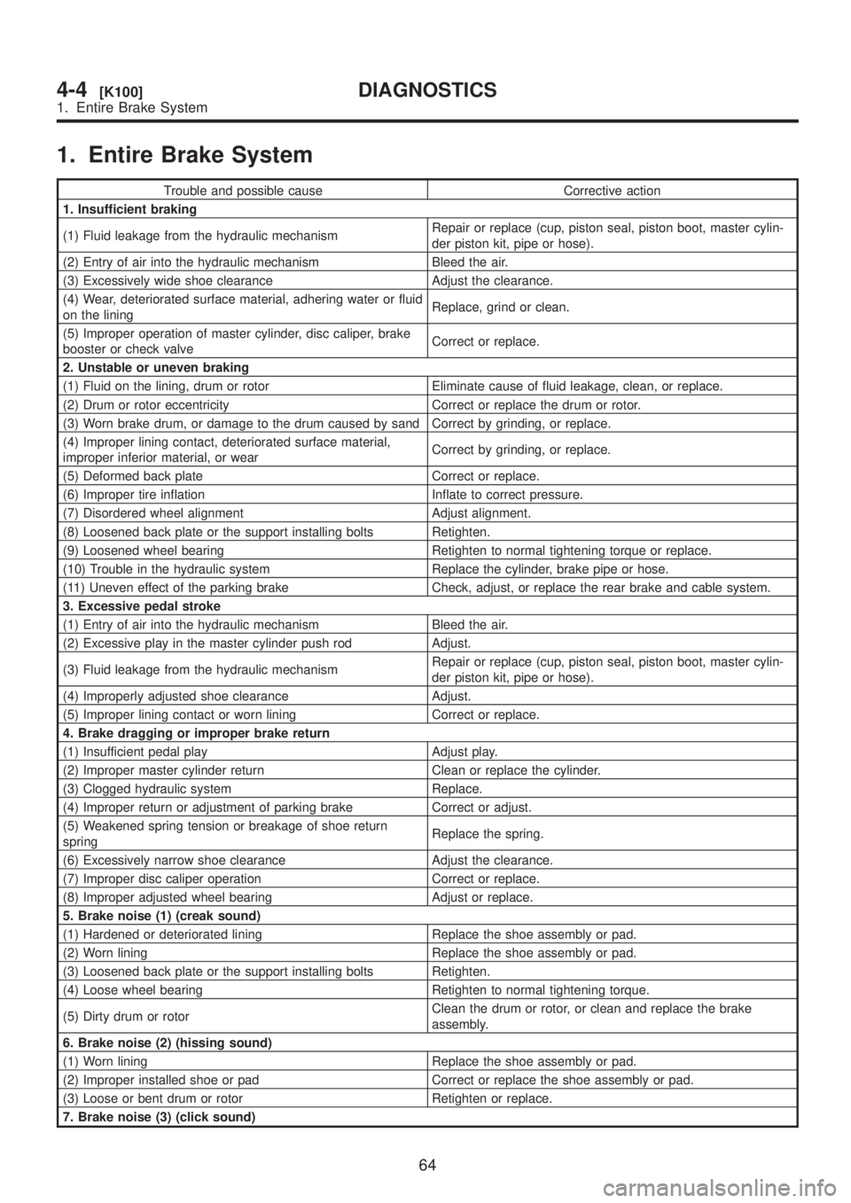
1. Entire Brake System
Trouble and possible cause Corrective action
1. Insufficient braking
(1) Fluid leakage from the hydraulic mechanismRepair or replace (cup, piston seal, piston boot, master cylin-
der piston kit, pipe or hose).
(2) Entry of air into the hydraulic mechanism Bleed the air.
(3) Excessively wide shoe clearance Adjust the clearance.
(4) Wear, deteriorated surface material, adhering water or fluid
on the liningReplace, grind or clean.
(5) Improper operation of master cylinder, disc caliper, brake
booster or check valveCorrect or replace.
2. Unstable or uneven braking
(1) Fluid on the lining, drum or rotor Eliminate cause of fluid leakage, clean, or replace.
(2) Drum or rotor eccentricity Correct or replace the drum or rotor.
(3) Worn brake drum, or damage to the drum caused by sand Correct by grinding, or replace.
(4) Improper lining contact, deteriorated surface material,
improper inferior material, or wearCorrect by grinding, or replace.
(5) Deformed back plate Correct or replace.
(6) Improper tire inflation Inflate to correct pressure.
(7) Disordered wheel alignment Adjust alignment.
(8) Loosened back plate or the support installing bolts Retighten.
(9) Loosened wheel bearing Retighten to normal tightening torque or replace.
(10) Trouble in the hydraulic system Replace the cylinder, brake pipe or hose.
(11) Uneven effect of the parking brake Check, adjust, or replace the rear brake and cable system.
3. Excessive pedal stroke
(1) Entry of air into the hydraulic mechanism Bleed the air.
(2) Excessive play in the master cylinder push rod Adjust.
(3) Fluid leakage from the hydraulic mechanismRepair or replace (cup, piston seal, piston boot, master cylin-
der piston kit, pipe or hose).
(4) Improperly adjusted shoe clearance Adjust.
(5) Improper lining contact or worn lining Correct or replace.
4. Brake dragging or improper brake return
(1) Insufficient pedal play Adjust play.
(2) Improper master cylinder return Clean or replace the cylinder.
(3) Clogged hydraulic system Replace.
(4) Improper return or adjustment of parking brake Correct or adjust.
(5) Weakened spring tension or breakage of shoe return
springReplace the spring.
(6) Excessively narrow shoe clearance Adjust the clearance.
(7) Improper disc caliper operation Correct or replace.
(8) Improper adjusted wheel bearing Adjust or replace.
5. Brake noise (1) (creak sound)
(1) Hardened or deteriorated lining Replace the shoe assembly or pad.
(2) Worn lining Replace the shoe assembly or pad.
(3) Loosened back plate or the support installing bolts Retighten.
(4) Loose wheel bearing Retighten to normal tightening torque.
(5) Dirty drum or rotorClean the drum or rotor, or clean and replace the brake
assembly.
6. Brake noise (2) (hissing sound)
(1) Worn lining Replace the shoe assembly or pad.
(2) Improper installed shoe or pad Correct or replace the shoe assembly or pad.
(3) Loose or bent drum or rotor Retighten or replace.
7. Brake noise (3) (click sound)
64
4-4[K100]DIAGNOSTICS
1. Entire Brake System
Page 944 of 1456

Trouble and possible cause Corrective action
In the case of the disc brake:
(1) Excessively worn pad or the support Replace the pad or the support.
In the case of the drum brake:
(1) Excessively worn shoe ridge Replace the back plate.
(2) Lack of oil on the shoe ridge surface and anchor Add more grease.
2. Hill Holder
CAUTION:
IDescription in parentheses is a characteris-
tic of hill holder and does not indicate abnor-
mality.
Depressing force required for clutch pedal
equipped to hill holder specifications is 20 to
29 N (2 to 3 kg, 4 to 7 lb) larger than the con-
ventional specifications, which does not con-
stitute abnormality.IWhen vehicle cannot travel (brake cannot be
released) because return spring is broken,
remove adjusting nut, disconnect clutch and
PHV, and then return PHV lever to release the
brake. (Be sure to apply the parking brake
before starting this operation.)
IThe hill holder may not be activated on a
slope of an extremely small inclination.
Trouble and possible cause Corrective action
1. Counterforce of clutch pedal is too strong.
(1) PHV cable is damaged or does not operate properly. Repair or replace.
(2) Lever of PHV is defective. Replace entire PHV assembly.
(3) Clutch system is anomalous. Refer to ªClutch and pedal cable systemº.
2. Vehicle does not stop on uphill road of 3É or higher inclination.
(1) Front side of vehicle is lowered. Refer to ªSuspensionº.
(2) PHV cable is broken. Replace.
(3) Play of clutch is excessive. Adjust.
(4) PHV cable is elongated. Adjust.
(5) Sealing of PHV is poor. Replace entire PHV assembly.
3. Shock is felt when starting.
(1) Poor adjustment of starting performance: Adjust.
(2) When depressing the brake pedal strongly:(The stronger brake pedal depressing force, the later hill
holder releases.)
(3) When starting on flat road after stopping reverse move-
ment:(Because hill holder is activated.)
4. Vehicle slips down when starting.
(1) PHV cable is elongated. Adjust.
(2) Clutch facing is worn out. Adjust or replace.
(3) Bracket (cable) or stay (PHV) is deformed. Repair or replace.
5. Vehicle cannot start after stoppage.
(1) Return spring is fatigued or broken. Replace.
(2) PHV lever won't return. Replace entire PHV assembly.
(3) When intentionally depressing brake pedal strongly:[When the brake pedal is depressed by a force of 1,177 N
(120 kg, 265 lb) or more.]
6. Abnormal sound is generated upon releasing brake pedal when stopping.
(1) Rotor and pad matched with each other due to inadequate
depressing force to brake pedal.(Abnormal sound is not generated when depressing brake
pedal a little stronger.)
7. Abnormal sound is generated when operating clutch pedal.
(1) Grease is inadequate for the hook of return spring and
sliding portion of PHV cable end.Apply grease.
(2) When releasing after maintaining high fluid pressure: (Flowing sound of fluid when releasing high fluid pressure.)
(3) Clutch system is anomalous. Refer to ªClutch and pedal cable systemº.
65
[K200]4-4DIAGNOSTICS
2. Hill Holder
Page 945 of 1456
Trouble and possible cause Corrective action
In the case of the disc brake:
(1) Excessively worn pad or the support Replace the pad or the support.
In the case of the drum brake:
(1) Excessively worn shoe ridge Replace the back plate.
(2) Lack of oil on the shoe ridge surface and anchor Add more grease.
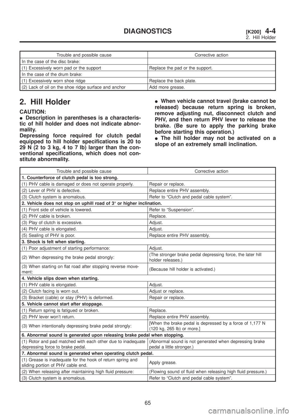
2. Hill Holder
CAUTION:
IDescription in parentheses is a characteris-
tic of hill holder and does not indicate abnor-
mality.
Depressing force required for clutch pedal
equipped to hill holder specifications is 20 to
29 N (2 to 3 kg, 4 to 7 lb) larger than the con-
ventional specifications, which does not con-
stitute abnormality.IWhen vehicle cannot travel (brake cannot be
released) because return spring is broken,
remove adjusting nut, disconnect clutch and
PHV, and then return PHV lever to release the
brake. (Be sure to apply the parking brake
before starting this operation.)
IThe hill holder may not be activated on a
slope of an extremely small inclination.
Trouble and possible cause Corrective action
1. Counterforce of clutch pedal is too strong.
(1) PHV cable is damaged or does not operate properly. Repair or replace.
(2) Lever of PHV is defective. Replace entire PHV assembly.
(3) Clutch system is anomalous. Refer to ªClutch and pedal cable systemº.
2. Vehicle does not stop on uphill road of 3É or higher inclination.
(1) Front side of vehicle is lowered. Refer to ªSuspensionº.
(2) PHV cable is broken. Replace.
(3) Play of clutch is excessive. Adjust.
(4) PHV cable is elongated. Adjust.
(5) Sealing of PHV is poor. Replace entire PHV assembly.
3. Shock is felt when starting.
(1) Poor adjustment of starting performance: Adjust.
(2) When depressing the brake pedal strongly:(The stronger brake pedal depressing force, the later hill
holder releases.)
(3) When starting on flat road after stopping reverse move-
ment:(Because hill holder is activated.)
4. Vehicle slips down when starting.
(1) PHV cable is elongated. Adjust.
(2) Clutch facing is worn out. Adjust or replace.
(3) Bracket (cable) or stay (PHV) is deformed. Repair or replace.
5. Vehicle cannot start after stoppage.
(1) Return spring is fatigued or broken. Replace.
(2) PHV lever won't return. Replace entire PHV assembly.
(3) When intentionally depressing brake pedal strongly:[When the brake pedal is depressed by a force of 1,177 N
(120 kg, 265 lb) or more.]
6. Abnormal sound is generated upon releasing brake pedal when stopping.
(1) Rotor and pad matched with each other due to inadequate
depressing force to brake pedal.(Abnormal sound is not generated when depressing brake
pedal a little stronger.)
7. Abnormal sound is generated when operating clutch pedal.
(1) Grease is inadequate for the hook of return spring and
sliding portion of PHV cable end.Apply grease.
(2) When releasing after maintaining high fluid pressure: (Flowing sound of fluid when releasing high fluid pressure.)
(3) Clutch system is anomalous. Refer to ªClutch and pedal cable systemº.
65
[K200]4-4DIAGNOSTICS
2. Hill Holder
Page 1074 of 1456
Process
No.Process name Job contents
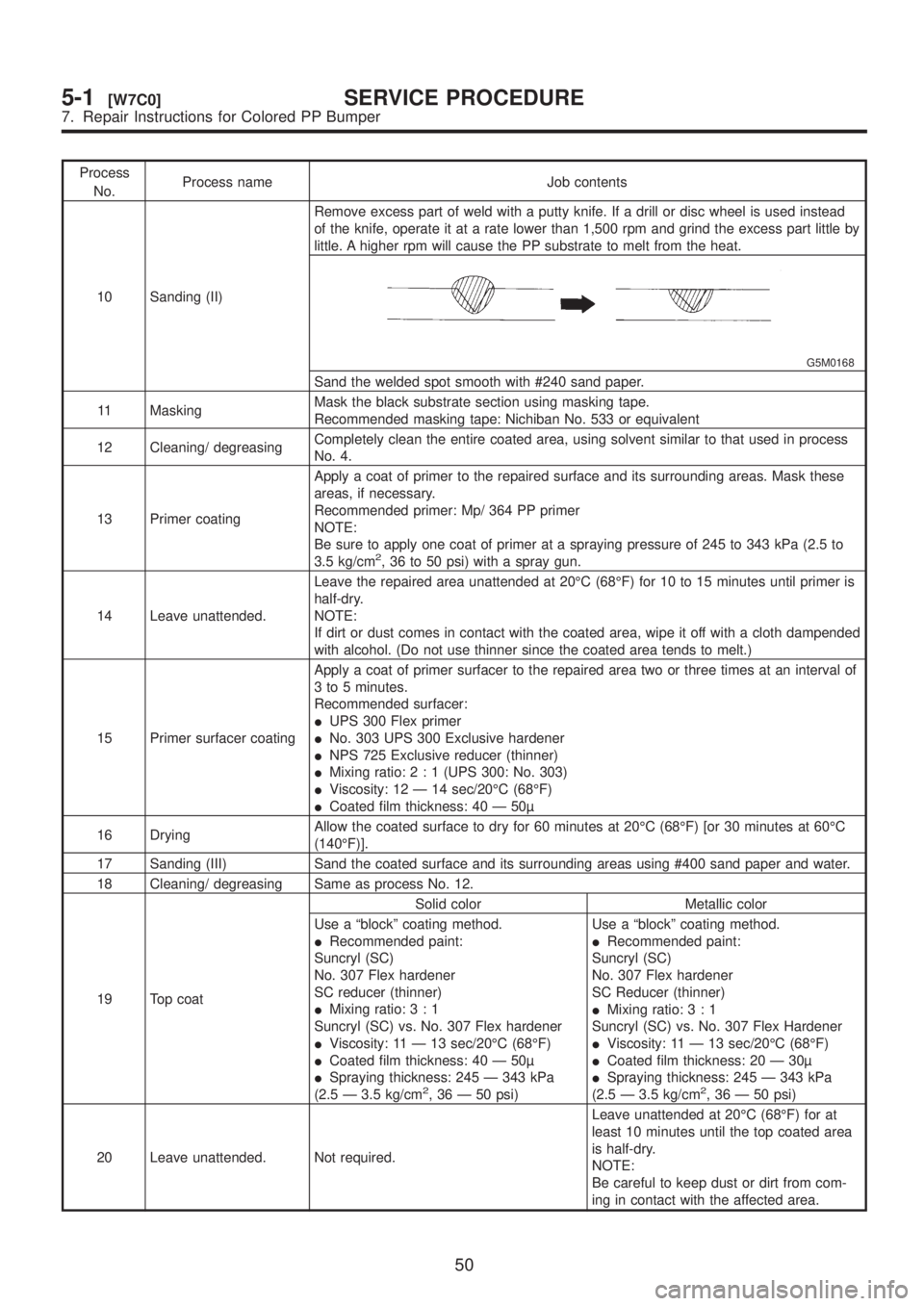
10 Sanding (II)Remove excess part of weld with a putty knife. If a drill or disc wheel is used instead
of the knife, operate it at a rate lower than 1,500 rpm and grind the excess part little by
little. A higher rpm will cause the PP substrate to melt from the heat.
G5M0168
Sand the welded spot smooth with #240 sand paper.
11 MaskingMask the black substrate section using masking tape.
Recommended masking tape: Nichiban No. 533 or equivalent
12 Cleaning/ degreasingCompletely clean the entire coated area, using solvent similar to that used in process
No. 4.
13 Primer coatingApply a coat of primer to the repaired surface and its surrounding areas. Mask these
areas, if necessary.
Recommended primer: Mp/ 364 PP primer
NOTE:
Be sure to apply one coat of primer at a spraying pressure of 245 to 343 kPa (2.5 to
3.5 kg/cm
2, 36 to 50 psi) with a spray gun.
14 Leave unattended.Leave the repaired area unattended at 20ÉC (68ÉF) for 10 to 15 minutes until primer is
half-dry.
NOTE:
If dirt or dust comes in contact with the coated area, wipe it off with a cloth dampended
with alcohol. (Do not use thinner since the coated area tends to melt.)
15 Primer surfacer coatingApply a coat of primer surfacer to the repaired area two or three times at an interval of
3 to 5 minutes.
Recommended surfacer:
IUPS 300 Flex primer
INo. 303 UPS 300 Exclusive hardener
INPS 725 Exclusive reducer (thinner)
IMixing ratio:2:1(UPS 300: No. 303)
IViscosity: 12 Ð 14 sec/20ÉC (68ÉF)
ICoated film thickness: 40 Ð 50
16 DryingAllow the coated surface to dry for 60 minutes at 20ÉC (68ÉF) [or 30 minutes at 60ÉC
(140ÉF)].
17 Sanding (III) Sand the coated surface and its surrounding areas using #400 sand paper and water.
18 Cleaning/ degreasing Same as process No. 12.
19 Top coatSolid color Metallic color
Use a ªblockº coating method.
IRecommended paint:
Suncryl (SC)
No. 307 Flex hardener
SC reducer (thinner)
IMixing ratio:3:1
Suncryl (SC) vs. No. 307 Flex hardener
IViscosity: 11 Ð 13 sec/20ÉC (68ÉF)
ICoated film thickness: 40 Ð 50
ISpraying thickness: 245 Ð 343 kPa
(2.5 Ð 3.5 kg/cm
2, 36 Ð 50 psi)Use a ªblockº coating method.
IRecommended paint:
Suncryl (SC)
No. 307 Flex hardener
SC Reducer (thinner)
IMixing ratio:3:1
Suncryl (SC) vs. No. 307 Flex Hardener
IViscosity: 11 Ð 13 sec/20ÉC (68ÉF)
ICoated film thickness: 20 Ð 30
ISpraying thickness: 245 Ð 343 kPa
(2.5 Ð 3.5 kg/cm2, 36 Ð 50 psi)
20 Leave unattended. Not required.Leave unattended at 20ÉC (68ÉF) for at
least 10 minutes until the top coated area
is half-dry.
NOTE:
Be careful to keep dust or dirt from com-
ing in contact with the affected area.
50
5-1[W7C0]SERVICE PROCEDURE
7. Repair Instructions for Colored PP Bumper
Page 1139 of 1456
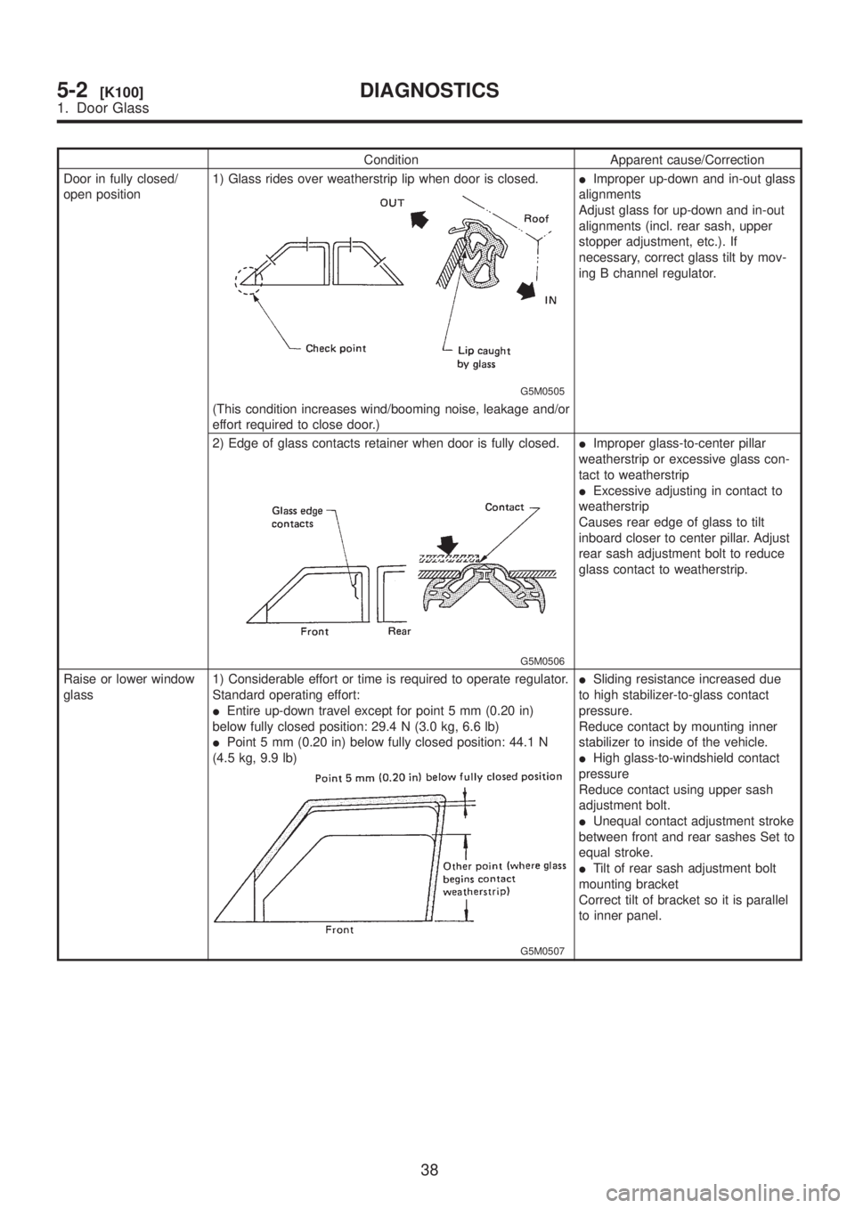
Condition Apparent cause/Correction
Door in fully closed/
open position1) Glass rides over weatherstrip lip when door is closed.
G5M0505
IImproper up-down and in-out glass
alignments
Adjust glass for up-down and in-out
alignments (incl. rear sash, upper
stopper adjustment, etc.). If
necessary, correct glass tilt by mov-
ing B channel regulator.
(This condition increases wind/booming noise, leakage and/or
effort required to close door.)
2) Edge of glass contacts retainer when door is fully closed.
G5M0506
IImproper glass-to-center pillar
weatherstrip or excessive glass con-
tact to weatherstrip
IExcessive adjusting in contact to
weatherstrip
Causes rear edge of glass to tilt
inboard closer to center pillar. Adjust
rear sash adjustment bolt to reduce
glass contact to weatherstrip.
Raise or lower window
glass1) Considerable effort or time is required to operate regulator.
Standard operating effort:
IEntire up-down travel except for point 5 mm (0.20 in)
below fully closed position: 29.4 N (3.0 kg, 6.6 lb)
IPoint 5 mm (0.20 in) below fully closed position: 44.1 N
(4.5 kg, 9.9 lb)
G5M0507
ISliding resistance increased due
to high stabilizer-to-glass contact
pressure.
Reduce contact by mounting inner
stabilizer to inside of the vehicle.
IHigh glass-to-windshield contact
pressure
Reduce contact using upper sash
adjustment bolt.
IUnequal contact adjustment stroke
between front and rear sashes Set to
equal stroke.
ITilt of rear sash adjustment bolt
mounting bracket
Correct tilt of bracket so it is parallel
to inner panel.
38
5-2[K100]DIAGNOSTICS
1. Door Glass
Page 1231 of 1456
4. Headlight
A: ADJUSTMENT
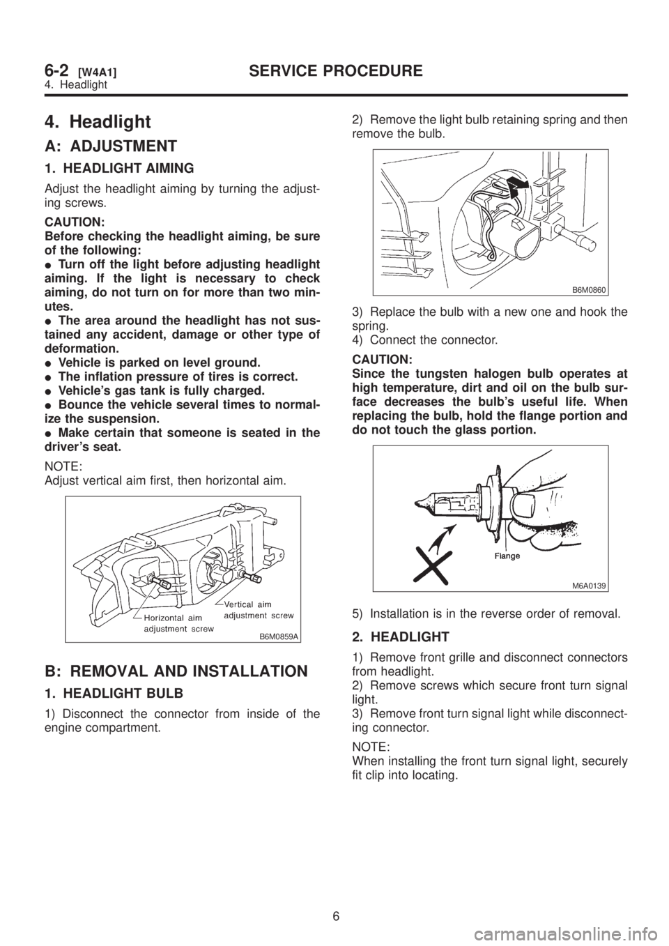
1. HEADLIGHT AIMING
Adjust the headlight aiming by turning the adjust-
ing screws.
CAUTION:
Before checking the headlight aiming, be sure
of the following:
ITurn off the light before adjusting headlight
aiming. If the light is necessary to check
aiming, do not turn on for more than two min-
utes.
IThe area around the headlight has not sus-
tained any accident, damage or other type of
deformation.
IVehicle is parked on level ground.
IThe inflation pressure of tires is correct.
IVehicle's gas tank is fully charged.
IBounce the vehicle several times to normal-
ize the suspension.
IMake certain that someone is seated in the
driver's seat.
NOTE:
Adjust vertical aim first, then horizontal aim.
B6M0859A
B: REMOVAL AND INSTALLATION
1. HEADLIGHT BULB
1) Disconnect the connector from inside of the
engine compartment.2) Remove the light bulb retaining spring and then
remove the bulb.
B6M0860
3) Replace the bulb with a new one and hook the
spring.
4) Connect the connector.
CAUTION:
Since the tungsten halogen bulb operates at
high temperature, dirt and oil on the bulb sur-
face decreases the bulb's useful life. When
replacing the bulb, hold the flange portion and
do not touch the glass portion.
M6A0139
5) Installation is in the reverse order of removal.
2. HEADLIGHT
1) Remove front grille and disconnect connectors
from headlight.
2) Remove screws which secure front turn signal
light.
3) Remove front turn signal light while disconnect-
ing connector.
NOTE:
When installing the front turn signal light, securely
fit clip into locating.
6
6-2[W4A1]SERVICE PROCEDURE
4. Headlight