Page 711 of 1456

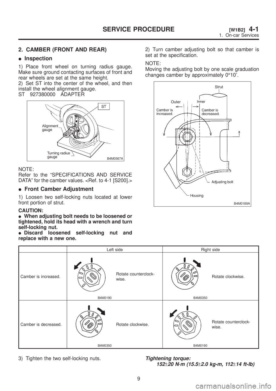
2. CAMBER (FRONT AND REAR)
IInspection
1) Place front wheel on turning radius gauge.
Make sure ground contacting surfaces of front and
rear wheels are set at the same height.
2) Set ST into the center of the wheel, and then
install the wheel alignment gauge.
ST 927380000 ADAPTER
B4M0567A
NOTE:
Refer to the ªSPECIFICATIONS AND SERVICE
DATAº for the camber values.
IFront Camber Adjustment
1) Loosen two self-locking nuts located at lower
front portion of strut.
CAUTION:
IWhen adjusting bolt needs to be loosened or
tightened, hold its head with a wrench and turn
self-locking nut.
IDiscard loosened self-locking nut and
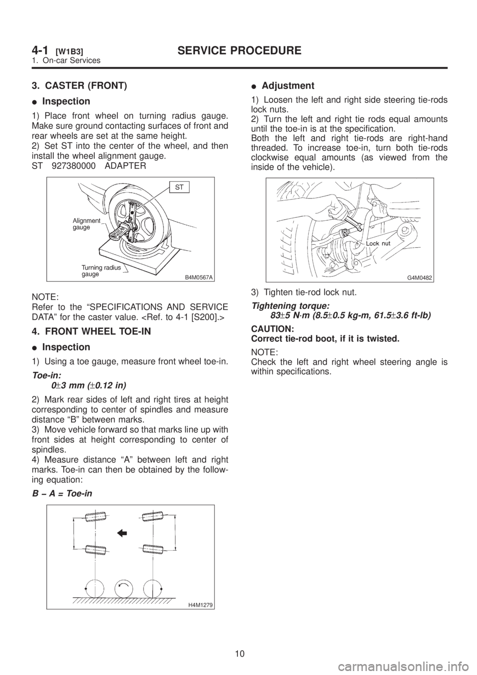
replace with a new one.2) Turn camber adjusting bolt so that camber is
set at the specification.
NOTE:
Moving the adjusting bolt by one scale graduation
changes camber by approximately 0É10¢.
B4M0189A
Left side Right side
Camber is increased.
B4M0190
Rotate counterclock-
wise.
B4M0350
Rotate clockwise.
Camber is decreased.
B4M0350
Rotate clockwise.
B4M0190
Rotate counterclock-
wise.
3) Tighten the two self-locking nuts.Tightening torque:
152
±20 N´m (15.5±2.0 kg-m, 112±14 ft-lb)
9
[W1B2]4-1SERVICE PROCEDURE
1. On-car Services
Page 712 of 1456

3. CASTER (FRONT)
IInspection
1) Place front wheel on turning radius gauge.
Make sure ground contacting surfaces of front and
rear wheels are set at the same height.
2) Set ST into the center of the wheel, and then
install the wheel alignment gauge.
ST 927380000 ADAPTER
B4M0567A
NOTE:
Refer to the ªSPECIFICATIONS AND SERVICE
DATAº for the caster value.
4. FRONT WHEEL TOE-IN
IInspection
1) Using a toe gauge, measure front wheel toe-in.
Toe-in:
0
±3mm(±0.12 in)
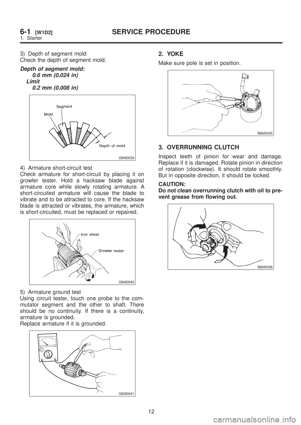
2) Mark rear sides of left and right tires at height
corresponding to center of spindles and measure
distance ªBº between marks.
3) Move vehicle forward so that marks line up with
front sides at height corresponding to center of
spindles.
4) Measure distance ªAº between left and right
marks. Toe-in can then be obtained by the follow-
ing equation:
B þ A = Toe-in
H4M1279
IAdjustment
1) Loosen the left and right side steering tie-rods
lock nuts.
2) Turn the left and right tie rods equal amounts
until the toe-in is at the specification.
Both the left and right tie-rods are right-hand
threaded. To increase toe-in, turn both tie-rods
clockwise equal amounts (as viewed from the
inside of the vehicle).
G4M0482
3) Tighten tie-rod lock nut.
Tightening torque:
83
±5 N´m (8.5±0.5 kg-m, 61.5±3.6 ft-lb)
CAUTION:
Correct tie-rod boot, if it is twisted.
NOTE:
Check the left and right wheel steering angle is
within specifications.
10
4-1[W1B3]SERVICE PROCEDURE
1. On-car Services
Page 1177 of 1456
![SUBARU LEGACY 1999 Service Repair Manual 6. Combination Switch
A: REMOVAL
1) Turn ignition switch off.
2) Disconnect ground cable from battery and wait
for at least 20 seconds before starting work.
3) Remove lower cover. <Ref. to 5-4 [W1A0]. SUBARU LEGACY 1999 Service Repair Manual 6. Combination Switch
A: REMOVAL
1) Turn ignition switch off.
2) Disconnect ground cable from battery and wait
for at least 20 seconds before starting work.
3) Remove lower cover. <Ref. to 5-4 [W1A0].](/manual-img/17/57435/w960_57435-1176.png)
6. Combination Switch
A: REMOVAL
1) Turn ignition switch off.
2) Disconnect ground cable from battery and wait
for at least 20 seconds before starting work.
3) Remove lower cover.
Disconnect airbag connector (AB3) and (AB8)
below steering column.
CAUTION:
Do not reconnect airbag connector at steering
column until combination switch is securely re-
installed.
G5M0312
4) Disconnect combination switch connectors
from body harness connector.
5) Set front wheels in straight ahead position.
Using TORX
TBIT T30, remove two TORXTbolts.
H5M0662A
6) Disconnect airbag connector on back of airbag
module. Remove airbag
module, and place it with pad side facing upward.
H5M0664
7) Using steering puller, remove steering wheel.
CAUTION:
Do not allow connector to interfere when
removing steering wheel.
G5M0332
8) Remove steering column covers.
9) Removing two retaining screws, remove combi-
nation switch.
B5M0106
B: ADJUSTMENT
1. CENTERING ROLL CONNECTOR
Before installing steering wheel, make sure to cen-
ter roll connector built into combination switch.
1) Make sure that front wheels are positioned
straight ahead.
2) Install steering gearbox, steering shaft and
combination switch properly. Turn roll connector
pin (A) clockwise until it stops.
3) Then, back off roll connector pin (A) approxi-
mately 2.65 turns until ªGº marks aligned.
B5M0457A
15
[W6B1]5-5SERVICE PROCEDURE
6. Combination Switch
Page 1193 of 1456

3) Depth of segment mold
Check the depth of segment mold.
Depth of segment mold:
0.6 mm (0.024 in)
Limit
0.2 mm (0.008 in)
G6M0039
4) Armature short-circuit test
Check armature for short-circuit by placing it on
growler tester. Hold a hacksaw blade against
armature core while slowly rotating armature. A
short-circuited armature will cause the blade to
vibrate and to be attracted to core. If the hacksaw
blade is attracted or vibrates, the armature, which
is short-circuited, must be replaced or repaired.
G6M0040
5) Armature ground test
Using circuit tester, touch one probe to the com-
mutator segment and the other to shaft. There
should be no continuity. If there is a continuity,
armature is grounded.
Replace armature if it is grounded.
G6M0041
2. YOKE
Make sure pole is set in position.
B6M0435
3. OVERRUNNING CLUTCH
Inspect teeth of pinion for wear and damage.
Replace if it is damaged. Rotate pinion in direction
of rotation (clockwise). It should rotate smoothly.
But in opposite direction, it should be locked.
CAUTION:
Do not clean overrunning clutch with oil to pre-
vent grease from flowing out.
B6M0436
12
6-1[W1D2]SERVICE PROCEDURE
1. Starter