1999 SUBARU LEGACY set clock
[x] Cancel search: set clockPage 46 of 1456
(4) Disconnect rear gate glass washer hose
from washer motor, then plug connection
with a suitable cap. (Wagon only)
(5) Remove the two bolts which hold washer
tank, then secure the tank away from work-
ing area.
B2M2023
(6) Disconnect spark plug cords from spark
plugs (#2 and #4 cylinders).
B2M2024
(7) Disconnect blow-by hose form rocker
cover (LH).
B2M2025
(8) Lift-up the vehicle.
(9) Remove under cover (LH).
(10) Place suitable container under the
vehicle.
(11) Remove rocker cover bolts, then
remove rocker cover (LH).
B2M2026
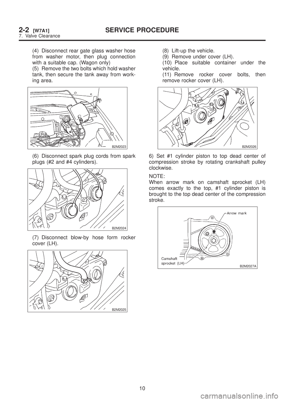
6) Set #1 cylinder piston to top dead center of
compression stroke by rotating crankshaft pulley
clockwise.
NOTE:
When arrow mark on camshaft sprocket (LH)
comes exactly to the top, #1 cylinder piston is
brought to the top dead center of the compression
stroke.
B2M2027A
10
2-2[W7A1]SERVICE PROCEDURE
7. Valve Clearance
Page 47 of 1456
7) Measure #1 cylinder valve clearance by using
thickness gauge.
CAUTION:
IInsert the thickness gauge in at as horizon-
tal a direction as a possible with respect to the
valve stem end face.
IMeasure exhaust valve clearances while lift-
ing-up the vehicle.
Valve clearance:
Intake: 0.20
±0.02 mm (0.0079±0.0008 in)
Exhaust: 0.25
±0.02 mm (0.0098±0.0008 in)
B2M2028A
8) If necessary, adjust the valve clearance.
9) Similar to measurement procedures used for #1
cylinder, measure #2, #3 and #4 cylinder valve
clearances.
NOTE:
IBe sure to set cylinder pistons to their respective
top dead centers on the compression stroke before
measuring valve clearances.
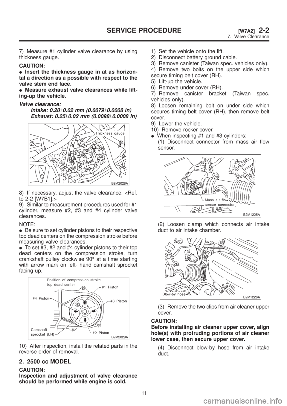
ITo set #3, #2 and #4 cylinder pistons to their top
dead centers on the compression stroke, turn
crankshaft pulley clockwise 90É at a time starting
with arrow mark on left- hand camshaft sprocket
facing up.
B2M2029A
10) After inspection, install the related parts in the
reverse order of removal.
2. 2500 cc MODEL
CAUTION:
Inspection and adjustment of valve clearance
should be performed while engine is cold.1) Set the vehicle onto the lift.
2) Disconnect battery ground cable.
3) Remove canister (Taiwan spec. vehicles only).
4) Remove two bolts on the upper side which
secure timing belt cover (RH).
5) Lift-up the vehicle.
6) Remove under cover (RH).
7) Remove canister bracket (Taiwan spec.
vehicles only).
8) Loosen remaining bolt on under side which
secures timing belt cover (RH), then remove belt
cover.
9) Lower the vehicle.
10) Remove rocker cover.
IWhen inspecting #1 and #3 cylinders;
(1) Disconnect connector from mass air flow
sensor.
B2M1225A
(2) Loosen clamp which connects air intake
duct to air intake chamber.
B2M1226A
(3) Remove the two clips from air cleaner upper
cover.
CAUTION:
Before installing air cleaner upper cover, align
hole(s) with protruding portions of air cleaner
lower case, then secure upper cover.
(4) Disconnect blow-by hose from air intake
duct.
11
[W7A2]2-2SERVICE PROCEDURE
7. Valve Clearance
Page 48 of 1456
(5) Remove air intake duct and air cleaner
upper cover as a unit.
B2M1227
(6) Remove air cleaner element.
(7) Remove air cleaner lower case.
S2M0179
(8) Disconnect spark plug cords from spark
plugs (#1 and #3 cylinders).
(9) Place suitable container under the vehicle.
(10) Disconnect PCV hose from rocker cover
(RH).
(11) Remove bolts, then remove rocker cover
(RH).
IWhen inspecting # 2 and #4 cylinders;
(1) Disconnect battery cables, and then
remove battery and battery carrier.
(2) Disconnect washer motor connectors.
(3) Disconnect washer hoses from washer
motors, then plug connections with suitable
caps.
(4) Remove washer tank.
(5) Disconnect spark plug cords from spark
plugs (#2 and #4 cylinders).
(6) Remove under cover (LH).
(7) Place suitable container under the vehicle.
(8) Disconnect PCV hose from rocker cover
(LH).
(9) Remove bolts, then remove rocker cover
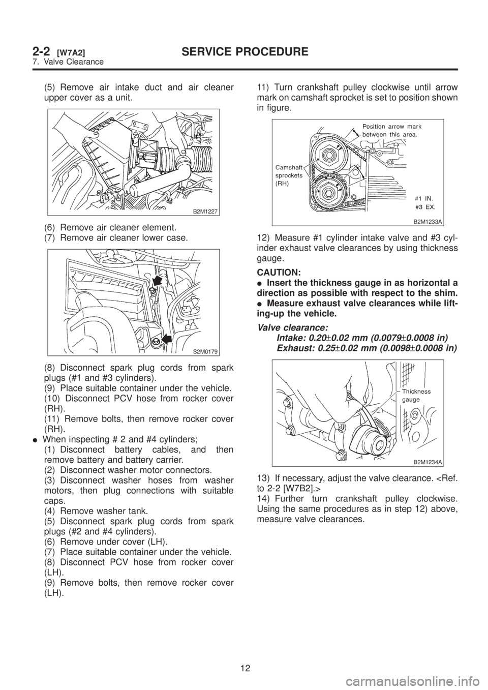
(LH).11) Turn crankshaft pulley clockwise until arrow
mark on camshaft sprocket is set to position shown
in figure.
B2M1233A
12) Measure #1 cylinder intake valve and #3 cyl-
inder exhaust valve clearances by using thickness
gauge.
CAUTION:
IInsert the thickness gauge in as horizontal a
direction as possible with respect to the shim.
IMeasure exhaust valve clearances while lift-
ing-up the vehicle.
Valve clearance:
Intake: 0.20
±0.02 mm (0.0079±0.0008 in)
Exhaust: 0.25
±0.02 mm (0.0098±0.0008 in)
B2M1234A
13) If necessary, adjust the valve clearance.
14) Further turn crankshaft pulley clockwise.
Using the same procedures as in step 12) above,
measure valve clearances.
12
2-2[W7A2]SERVICE PROCEDURE
7. Valve Clearance
Page 49 of 1456

(1) Set arrow mark on camshaft sprocket to
position shown in figure, and measure #2 cylin-
der exhaust valve and #3 cylinder intake valve
clearances.
B2M1235A
(2) Set arrow mark on camshaft sprocket to
position shown in figure, and measure #2 cylin-
der intake valve and #4 cylinder exhaust valve
clearances.
B2M1236A
(3) Set arrow mark on camshaft sprocket to
position shown in figure, and measure #1 cylin-
der exhaust valve and #4 cylinder intake valve
clearances.
B2M1237A
15) After inspection, install the related parts in the
reverse order of removal.
B: ADJUSTMENT
1. 2200 cc MODEL
CAUTION:
Adjustment of valve clearance should be per-
formed while engine is cold.
1) Set #1 cylinder piston to top dead center of
compression stroke by rotating crankshaft pulley
clockwise.
NOTE:
When arrow mark on camshaft sprocket (LH)
comes exactly to the top, #1 cylinder piston is
brought to the top dead center of the compression
stroke.
B2M2027A
13
[W7B1]2-2SERVICE PROCEDURE
7. Valve Clearance
Page 50 of 1456

2) Adjust the #1 cylinder valve clearance.
(1) Loosen the valve rocker nut and screw.
(2) Place suitable thickness gauge.
(3) While noting valve clearance, tighten valve
rocker adjust screw.
(4) When specified valve clearance is obtained,
tighten valve rocker nut.
Tightening torque:
10
±1 N´m (1.0±0.1 kg-m, 7.2±0.7 ft-lb)
CAUTION:
IInsert the thickness gauge in at as horizon-
tal a direction as possible with respect to the
valve stem end face.
IAdjust exhaust valve clearances while lift-
ing-up the vehicle.
Valve clearance:
Intake: 0.20
±0.02 mm (0.0079±0.0008 in)
Exhaust: 0.25
±0.02 mm (0.0098±0.0008 in)
B2M2030A
(a) Thickness gauge
(b) Valve rocker nut
(c) Valve rocker screw
3) Ensure that valve clearances are within speci-
fications.
4) Turn crankshaft two complete rotations until #1
cylinder piston is again set to top dead center on
compression stroke.
5) Ensure that valve clearances are within speci-
fications. If necessary, re-adjust valve clearances.6) Similar to adjustment procedures used for #1
cylinder, adjust #2, #3 and #4 cylinder valve clear-
ances.
NOTE:
IBe sure to set cylinder pistons to their respective
top dead centers on the compression stroke before
adjusting valve clearances.
ITo set #3, #2 and #4 cylinder pistons to their top
dead centers on the compression stroke, turn
crankshaft pulley clockwise 90É at a time starting
with arrow mark on left-hand camshaft sprocket
facing up.
B2M2029A
2. 2500 cc MODEL
CAUTION:
Adjustment of valve clearance should be per-
formed while engine is cold.
1) Measure all valve clearances.
NOTE:
Record each valve clearance after it has been
measured.
B2M1234A
14
2-2[W7B2]SERVICE PROCEDURE
7. Valve Clearance
Page 54 of 1456
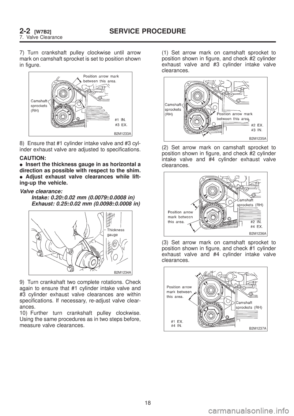
7) Turn crankshaft pulley clockwise until arrow
mark on camshaft sprocket is set to position shown
in figure.
B2M1233A
8) Ensure that #1 cylinder intake valve and #3 cyl-
inder exhaust valve are adjusted to specifications.
CAUTION:
IInsert the thickness gauge in as horizontal a
direction as possible with respect to the shim.
IAdjust exhaust valve clearances while lift-
ing-up the vehicle.
Valve clearance:
Intake: 0.20
±0.02 mm (0.0079±0.0008 in)
Exhaust: 0.25
±0.02 mm (0.0098±0.0008 in)
B2M1234A
9) Turn crankshaft two complete rotations. Check
again to ensure that #1 cylinder intake valve and
#3 cylinder exhaust valve clearances are within
specifications. If necessary, re-adjust valve clear-
ances.
10) Further turn crankshaft pulley clockwise.
Using the same procedures as in two steps before,
measure valve clearances.(1) Set arrow mark on camshaft sprocket to
position shown in figure, and check #2 cylinder
exhaust valve and #3 cylinder intake valve
clearances.
B2M1235A
(2) Set arrow mark on camshaft sprocket to
position shown in figure, and check #2 cylinder
intake valve and #4 cylinder exhaust valve
clearances.
B2M1236A
(3) Set arrow mark on camshaft sprocket to
position shown in figure, and check #1 cylinder
exhaust valve and #4 cylinder intake valve
clearances.
B2M1237A
18
2-2[W7B2]SERVICE PROCEDURE
7. Valve Clearance
Page 165 of 1456
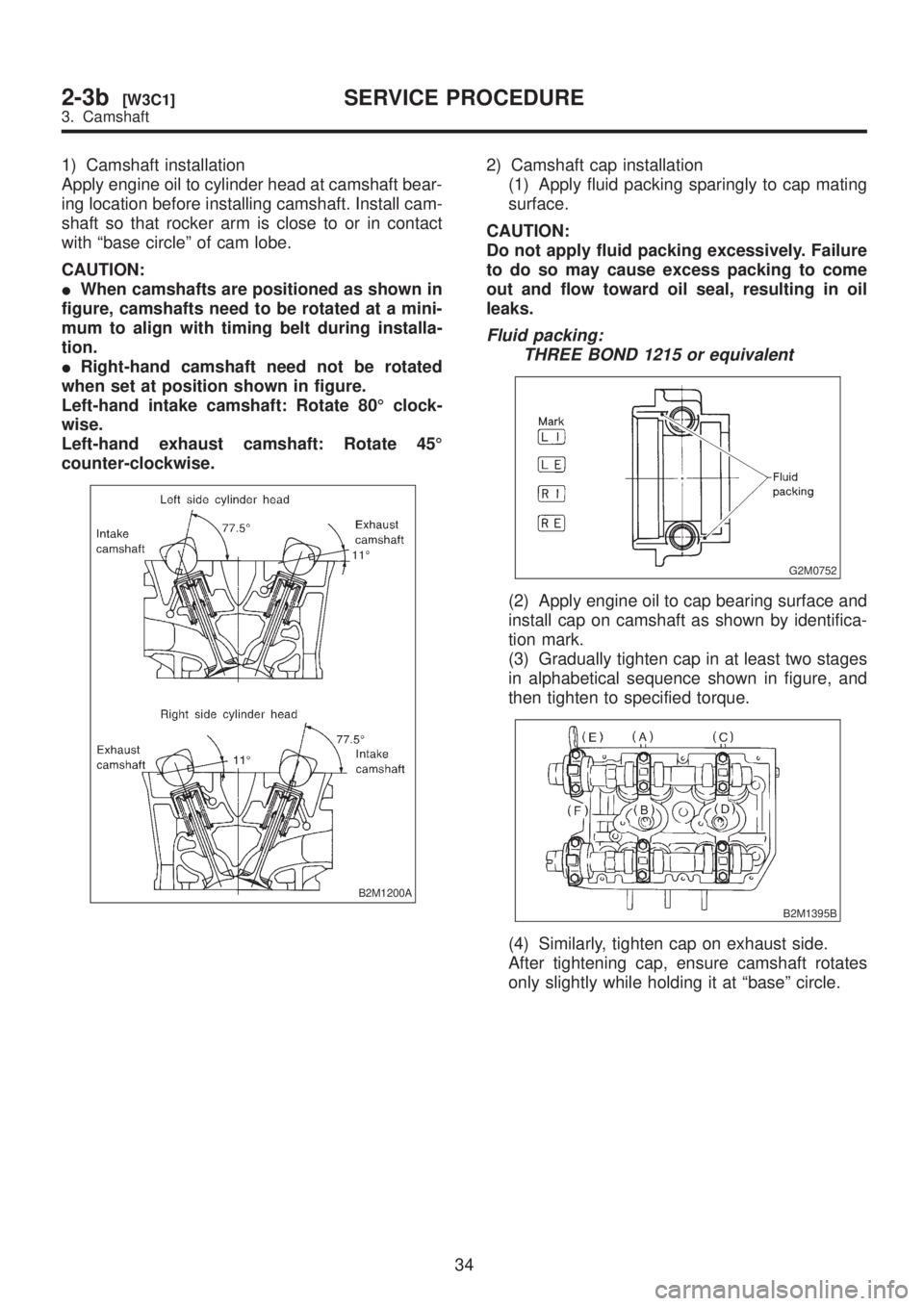
1) Camshaft installation
Apply engine oil to cylinder head at camshaft bear-
ing location before installing camshaft. Install cam-
shaft so that rocker arm is close to or in contact
with ªbase circleº of cam lobe.
CAUTION:
IWhen camshafts are positioned as shown in
figure, camshafts need to be rotated at a mini-
mum to align with timing belt during installa-
tion.
IRight-hand camshaft need not be rotated
when set at position shown in figure.
Left-hand intake camshaft: Rotate 80É clock-
wise.
Left-hand exhaust camshaft: Rotate 45É
counter-clockwise.
B2M1200A
2) Camshaft cap installation
(1) Apply fluid packing sparingly to cap mating
surface.
CAUTION:
Do not apply fluid packing excessively. Failure
to do so may cause excess packing to come
out and flow toward oil seal, resulting in oil
leaks.
Fluid packing:
THREE BOND 1215 or equivalent
G2M0752
(2) Apply engine oil to cap bearing surface and
install cap on camshaft as shown by identifica-
tion mark.
(3) Gradually tighten cap in at least two stages
in alphabetical sequence shown in figure, and
then tighten to specified torque.
B2M1395B
(4) Similarly, tighten cap on exhaust side.
After tightening cap, ensure camshaft rotates
only slightly while holding it at ªbaseº circle.
34
2-3b[W3C1]SERVICE PROCEDURE
3. Camshaft
Page 628 of 1456
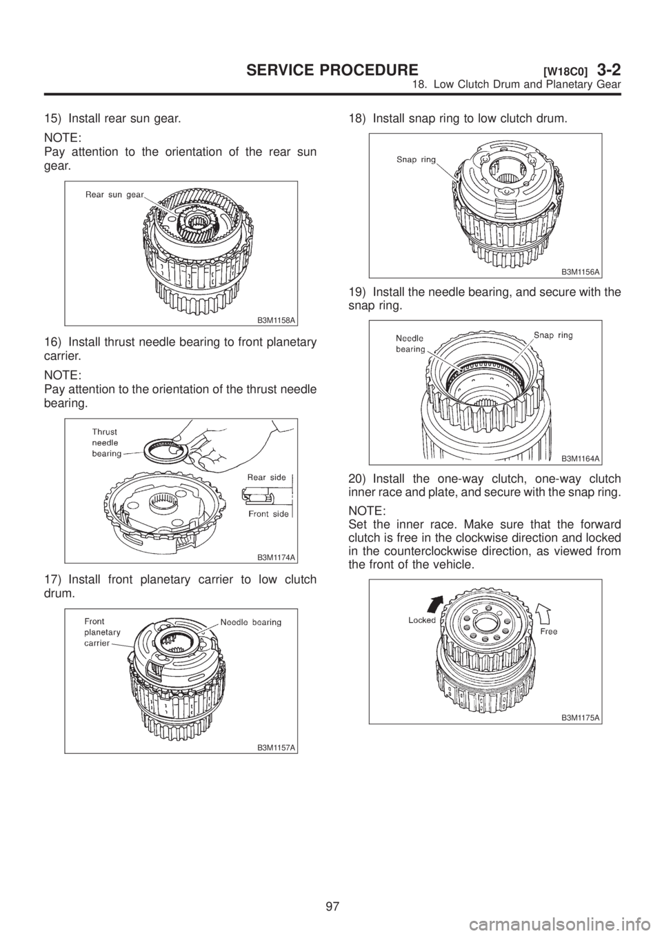
15) Install rear sun gear.
NOTE:
Pay attention to the orientation of the rear sun
gear.
B3M1158A
16) Install thrust needle bearing to front planetary
carrier.
NOTE:
Pay attention to the orientation of the thrust needle
bearing.
B3M1174A
17) Install front planetary carrier to low clutch
drum.
B3M1157A
18) Install snap ring to low clutch drum.
B3M1156A
19) Install the needle bearing, and secure with the
snap ring.
B3M1164A
20) Install the one-way clutch, one-way clutch
inner race and plate, and secure with the snap ring.
NOTE:
Set the inner race. Make sure that the forward
clutch is free in the clockwise direction and locked
in the counterclockwise direction, as viewed from
the front of the vehicle.
B3M1175A
97
[W18C0]3-2SERVICE PROCEDURE
18. Low Clutch Drum and Planetary Gear