1999 SUBARU LEGACY service indicator
[x] Cancel search: service indicatorPage 898 of 1456
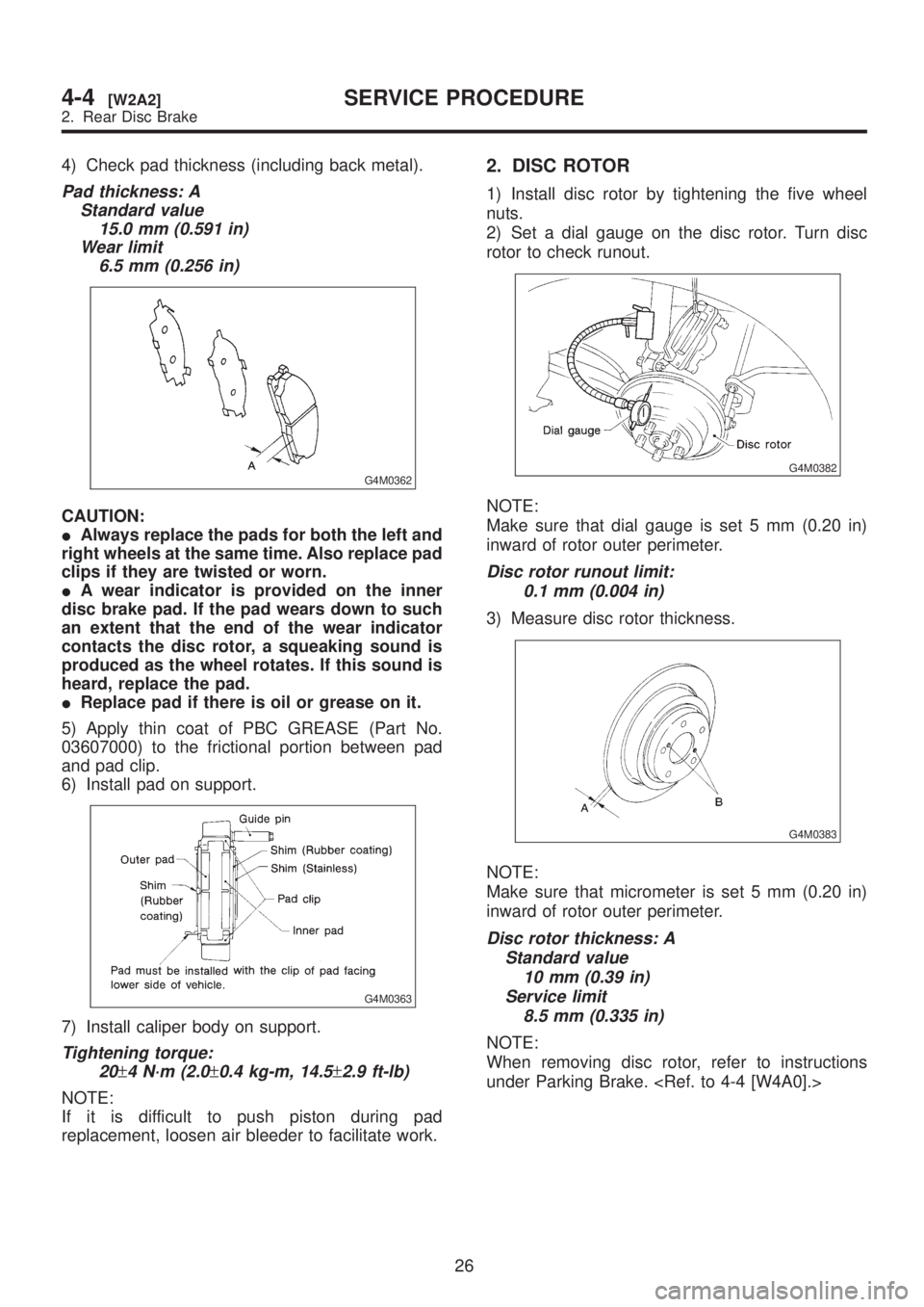
4) Check pad thickness (including back metal).
Pad thickness: A
Standard value
15.0 mm (0.591 in)
Wear limit
6.5 mm (0.256 in)
G4M0362
CAUTION:
IAlways replace the pads for both the left and
right wheels at the same time. Also replace pad
clips if they are twisted or worn.
IA wear indicator is provided on the inner
disc brake pad. If the pad wears down to such
an extent that the end of the wear indicator
contacts the disc rotor, a squeaking sound is
produced as the wheel rotates. If this sound is
heard, replace the pad.
IReplace pad if there is oil or grease on it.
5) Apply thin coat of PBC GREASE (Part No.
03607000) to the frictional portion between pad
and pad clip.
6) Install pad on support.
G4M0363
7) Install caliper body on support.
Tightening torque:
20
±4 N´m (2.0±0.4 kg-m, 14.5±2.9 ft-lb)
NOTE:
If it is difficult to push piston during pad
replacement, loosen air bleeder to facilitate work.
2. DISC ROTOR
1) Install disc rotor by tightening the five wheel
nuts.
2) Set a dial gauge on the disc rotor. Turn disc
rotor to check runout.
G4M0382
NOTE:
Make sure that dial gauge is set 5 mm (0.20 in)
inward of rotor outer perimeter.
Disc rotor runout limit:
0.1 mm (0.004 in)
3) Measure disc rotor thickness.
G4M0383
NOTE:
Make sure that micrometer is set 5 mm (0.20 in)
inward of rotor outer perimeter.
Disc rotor thickness: A
Standard value
10 mm (0.39 in)
Service limit
8.5 mm (0.335 in)
NOTE:
When removing disc rotor, refer to instructions
under Parking Brake.
26
4-4[W2A2]SERVICE PROCEDURE
2. Rear Disc Brake
Page 901 of 1456
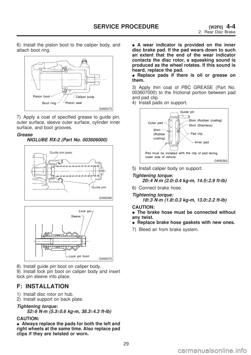
6) Install the piston boot to the caliper body, and
attach boot ring.
G4M0373
7) Apply a coat of specified grease to guide pin,
outer surface, sleeve outer surface, cylinder inner
surface, and boot grooves.
Grease
NIGLUBE RX-2 (Part No. 003606000)
G4M0390
G4M0375
8) Install guide pin boot on caliper body.
9) Install lock pin boot on caliper body and insert
lock pin sleeve into place.
F: INSTALLATION
1) Install disc rotor on hub.
2) Install support on back plate.
Tightening torque:
52
±6 N´m (5.3±0.6 kg-m, 38.3±4.3 ft-lb)
CAUTION:
IAlways replace the pads for both the left and
right wheels at the same time. Also replace pad
clips if they are twisted or worn.IA wear indicator is provided on the inner
disc brake pad. If the pad wears down to such
an extent that the end of the wear indicator
contacts the disc rotor, a squeaking sound is
produced as the wheel rotates. If this sound is
heard, replace the pad.
IReplace pads if there is oil or grease on
them.
3) Apply thin coat of PBC GREASE (Part No.
003607000) to the frictional portion between pad
and pad clip.
4) Install pads on support.
G4M0363
5) Install caliper body on support.
Tightening torque:
20
±4 N´m (2.0±0.4 kg-m, 14.5±2.9 ft-lb)
6) Connect brake hose.
Tightening torque:
18
±3 N´m (1.8±0.3 kg-m, 13.0±2.2 ft-lb)
CAUTION:
IThe brake hose must be connected without
any twist.
IReplace brake hose gaskets with new ones.
7) Bleed air from brake system.
29
[W2F0]4-4SERVICE PROCEDURE
2. Rear Disc Brake
Page 909 of 1456
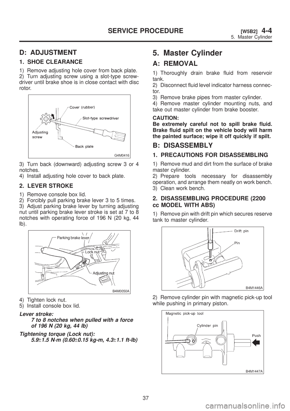
D: ADJUSTMENT
1. SHOE CLEARANCE
1) Remove adjusting hole cover from back plate.
2) Turn adjusting screw using a slot-type screw-
driver until brake shoe is in close contact with disc
rotor.
G4M0416
3) Turn back (downward) adjusting screw 3 or 4
notches.
4) Install adjusting hole cover to back plate.
2. LEVER STROKE
1) Remove console box lid.
2) Forcibly pull parking brake lever 3 to 5 times.
3) Adjust parking brake lever by turning adjusting
nut until parking brake lever stroke is set at 7 to 8
notches with operating force of 196 N (20 kg, 44
lb).
B4M0050A
4) Tighten lock nut.
5) Install console box lid.
Lever stroke:
7 to 8 notches when pulled with a force
of 196 N (20 kg, 44 lb)
Tightening torque (Lock nut):
5.9
±1.5 N´m (0.60±0.15 kg-m, 4.3±1.1 ft-lb)
5. Master Cylinder
A: REMOVAL
1) Thoroughly drain brake fluid from reservoir
tank.
2) Disconnect fluid level indicator harness connec-
tor.
3) Remove brake pipes from master cylinder.
4) Remove master cylinder mounting nuts, and
take out master cylinder from brake booster.
CAUTION:
Be extremely careful not to spill brake fluid.
Brake fluid spilt on the vehicle body will harm
the painted surface; wipe it off quickly if spilt.
B: DISASSEMBLY
1. PRECAUTIONS FOR DISASSEMBLING
1) Remove mud and dirt from the surface of brake
master cylinder.
2) Prepare tools necessary for disassembly
operation, and arrange them neatly on work bench.
3) Clean work bench.
2. DISASSEMBLING PROCEDURE (2200
cc MODEL WITH ABS)
1) Remove pin with drift pin which secures reserve
tank to master cylinder.
B4M1446A
2) Remove cylinder pin with magnetic pick-up tool
while pushing in primary piston.
B4M1447A
37
[W5B2]4-4SERVICE PROCEDURE
5. Master Cylinder
Page 910 of 1456
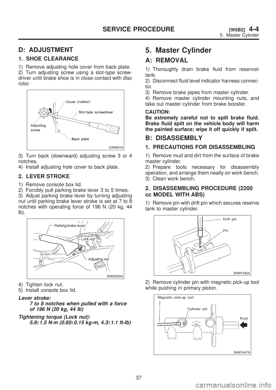
D: ADJUSTMENT
1. SHOE CLEARANCE
1) Remove adjusting hole cover from back plate.
2) Turn adjusting screw using a slot-type screw-
driver until brake shoe is in close contact with disc
rotor.
G4M0416
3) Turn back (downward) adjusting screw 3 or 4
notches.
4) Install adjusting hole cover to back plate.
2. LEVER STROKE
1) Remove console box lid.
2) Forcibly pull parking brake lever 3 to 5 times.
3) Adjust parking brake lever by turning adjusting
nut until parking brake lever stroke is set at 7 to 8
notches with operating force of 196 N (20 kg, 44
lb).
B4M0050A
4) Tighten lock nut.
5) Install console box lid.
Lever stroke:
7 to 8 notches when pulled with a force
of 196 N (20 kg, 44 lb)
Tightening torque (Lock nut):
5.9
±1.5 N´m (0.60±0.15 kg-m, 4.3±1.1 ft-lb)
5. Master Cylinder
A: REMOVAL
1) Thoroughly drain brake fluid from reservoir
tank.
2) Disconnect fluid level indicator harness connec-
tor.
3) Remove brake pipes from master cylinder.
4) Remove master cylinder mounting nuts, and
take out master cylinder from brake booster.
CAUTION:
Be extremely careful not to spill brake fluid.
Brake fluid spilt on the vehicle body will harm
the painted surface; wipe it off quickly if spilt.
B: DISASSEMBLY
1. PRECAUTIONS FOR DISASSEMBLING
1) Remove mud and dirt from the surface of brake
master cylinder.
2) Prepare tools necessary for disassembly
operation, and arrange them neatly on work bench.
3) Clean work bench.
2. DISASSEMBLING PROCEDURE (2200
cc MODEL WITH ABS)
1) Remove pin with drift pin which secures reserve
tank to master cylinder.
B4M1446A
2) Remove cylinder pin with magnetic pick-up tool
while pushing in primary piston.
B4M1447A
37
[W5B2]4-4SERVICE PROCEDURE
5. Master Cylinder
Page 913 of 1456
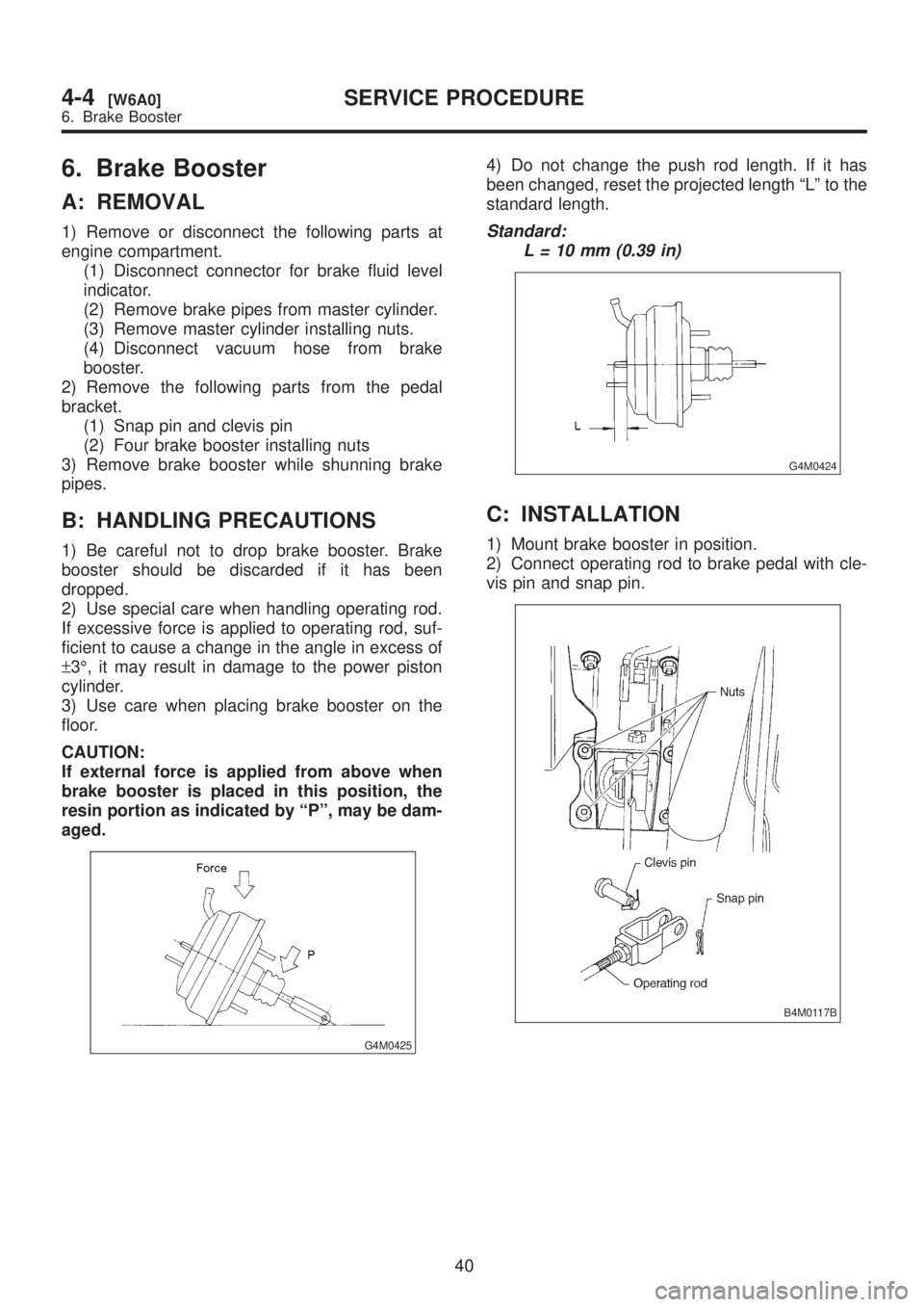
6. Brake Booster
A: REMOVAL
1) Remove or disconnect the following parts at
engine compartment.
(1) Disconnect connector for brake fluid level
indicator.
(2) Remove brake pipes from master cylinder.
(3) Remove master cylinder installing nuts.
(4) Disconnect vacuum hose from brake
booster.
2) Remove the following parts from the pedal
bracket.
(1) Snap pin and clevis pin
(2) Four brake booster installing nuts
3) Remove brake booster while shunning brake
pipes.
B: HANDLING PRECAUTIONS
1) Be careful not to drop brake booster. Brake
booster should be discarded if it has been
dropped.
2) Use special care when handling operating rod.
If excessive force is applied to operating rod, suf-
ficient to cause a change in the angle in excess of
±3É, it may result in damage to the power piston
cylinder.
3) Use care when placing brake booster on the
floor.
CAUTION:
If external force is applied from above when
brake booster is placed in this position, the
resin portion as indicated by ªPº, may be dam-
aged.
G4M0425
4) Do not change the push rod length. If it has
been changed, reset the projected length ªLº to the
standard length.
Standard:
L = 10 mm (0.39 in)
G4M0424
C: INSTALLATION
1) Mount brake booster in position.
2) Connect operating rod to brake pedal with cle-
vis pin and snap pin.
B4M0117B
40
4-4[W6A0]SERVICE PROCEDURE
6. Brake Booster
Page 914 of 1456
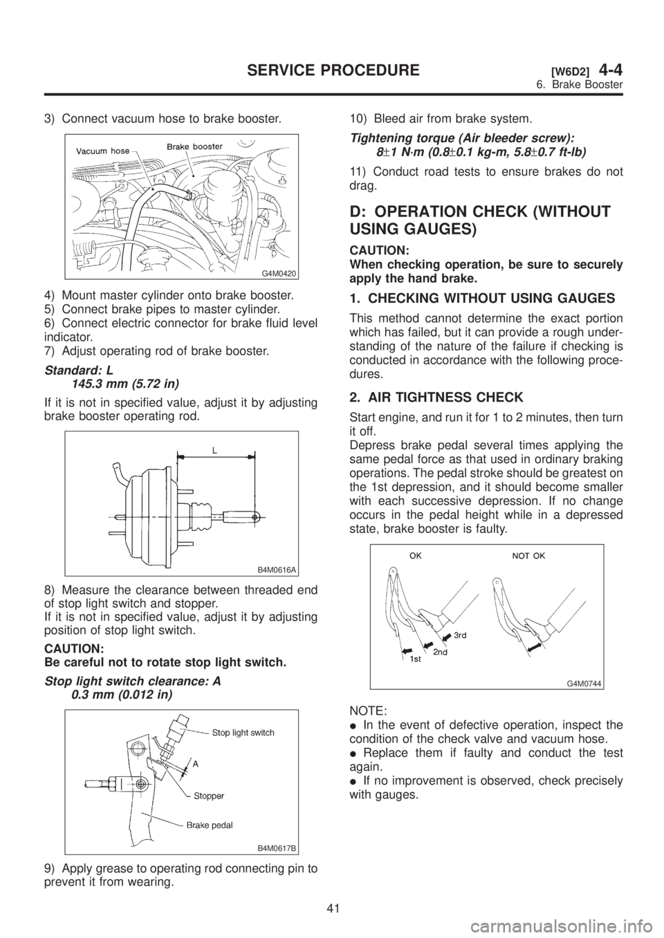
3) Connect vacuum hose to brake booster.
G4M0420
4) Mount master cylinder onto brake booster.
5) Connect brake pipes to master cylinder.
6) Connect electric connector for brake fluid level
indicator.
7) Adjust operating rod of brake booster.
Standard: L
145.3 mm (5.72 in)
If it is not in specified value, adjust it by adjusting
brake booster operating rod.
B4M0616A
8) Measure the clearance between threaded end
of stop light switch and stopper.
If it is not in specified value, adjust it by adjusting
position of stop light switch.
CAUTION:
Be careful not to rotate stop light switch.
Stop light switch clearance: A
0.3 mm (0.012 in)
B4M0617B
9) Apply grease to operating rod connecting pin to
prevent it from wearing.10) Bleed air from brake system.
Tightening torque (Air bleeder screw):
8
±1 N´m (0.8±0.1 kg-m, 5.8±0.7 ft-lb)
11) Conduct road tests to ensure brakes do not
drag.
D: OPERATION CHECK (WITHOUT
USING GAUGES)
CAUTION:
When checking operation, be sure to securely
apply the hand brake.
1. CHECKING WITHOUT USING GAUGES
This method cannot determine the exact portion
which has failed, but it can provide a rough under-
standing of the nature of the failure if checking is
conducted in accordance with the following proce-
dures.
2. AIR TIGHTNESS CHECK
Start engine, and run it for 1 to 2 minutes, then turn
it off.
Depress brake pedal several times applying the
same pedal force as that used in ordinary braking
operations. The pedal stroke should be greatest on
the 1st depression, and it should become smaller
with each successive depression. If no change
occurs in the pedal height while in a depressed
state, brake booster is faulty.
G4M0744
NOTE:
IIn the event of defective operation, inspect the
condition of the check valve and vacuum hose.
IReplace them if faulty and conduct the test
again.
IIf no improvement is observed, check precisely
with gauges.
41
[W6D2]4-4SERVICE PROCEDURE
6. Brake Booster
Page 1226 of 1456
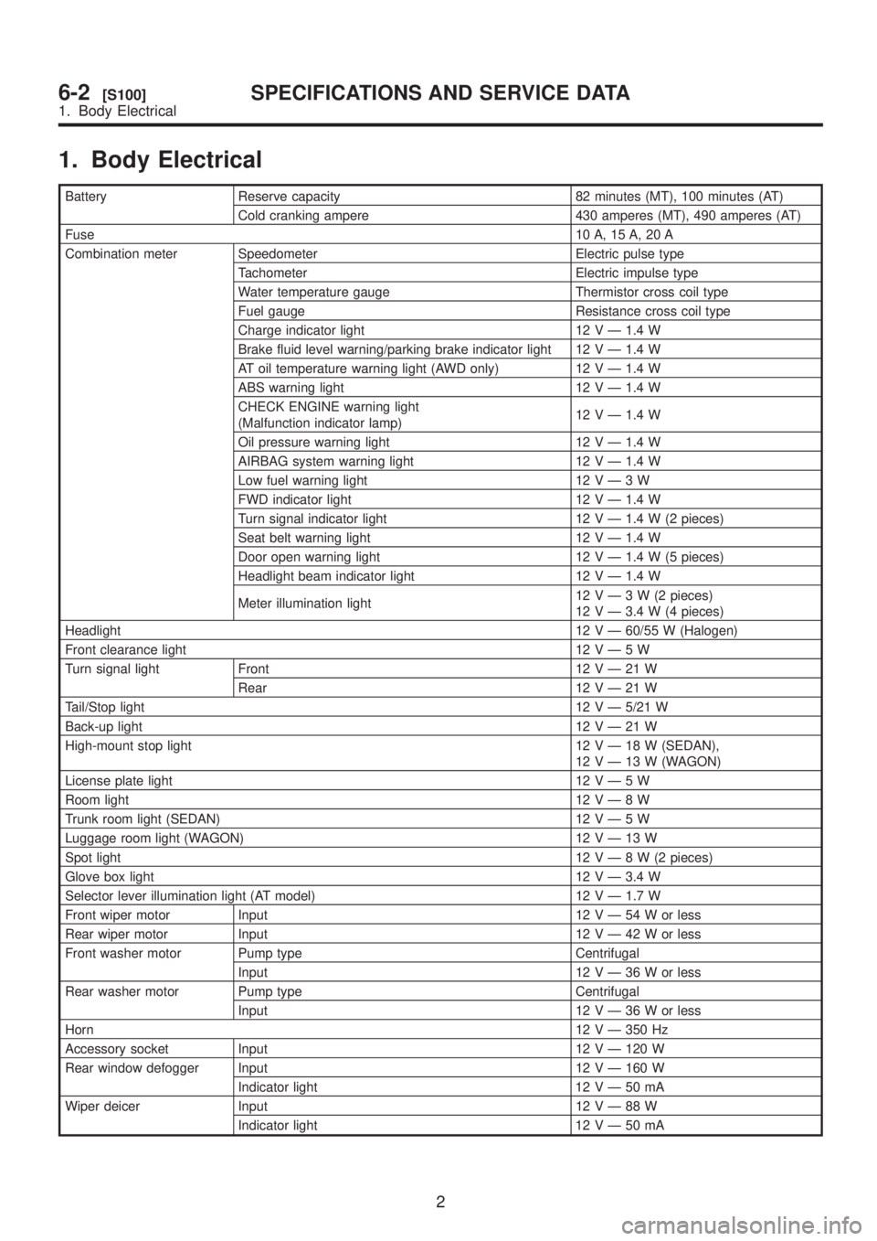
1. Body Electrical
Battery Reserve capacity 82 minutes (MT), 100 minutes (AT)
Cold cranking ampere 430 amperes (MT), 490 amperes (AT)
Fuse10 A, 15 A, 20 A
Combination meter Speedometer Electric pulse type
Tachometer Electric impulse type
Water temperature gauge Thermistor cross coil type
Fuel gauge Resistance cross coil type
Charge indicator light 12 V Ð 1.4 W
Brake fluid level warning/parking brake indicator light 12 V Ð 1.4 W
AT oil temperature warning light (AWD only) 12 V Ð 1.4 W
ABS warning light 12 V Ð 1.4 W
CHECK ENGINE warning light
(Malfunction indicator lamp)12 V Ð 1.4 W
Oil pressure warning light 12 V Ð 1.4 W
AIRBAG system warning light 12 V Ð 1.4 W
Low fuel warning light 12VÐ3W
FWD indicator light 12 V Ð 1.4 W
Turn signal indicator light 12 V Ð 1.4 W (2 pieces)
Seat belt warning light 12 V Ð 1.4 W
Door open warning light 12 V Ð 1.4 W (5 pieces)
Headlight beam indicator light 12 V Ð 1.4 W
Meter illumination light12VÐ3W(2pieces)
12 V Ð 3.4 W (4 pieces)
Headlight12 V Ð 60/55 W (Halogen)
Front clearance light 12VÐ5W
Turn signal light Front 12VÐ21W
Rear 12VÐ21W
Tail/Stop light12 V Ð 5/21 W
Back-up light12VÐ21W
High-mount stop light 12VÐ18W(SEDAN),
12VÐ13W(WAGON)
License plate light 12VÐ5W
Room light12VÐ8W
Trunk room light (SEDAN) 12VÐ5W
Luggage room light (WAGON) 12VÐ13W
Spot light12VÐ8W(2pieces)
Glove box light 12 V Ð 3.4 W
Selector lever illumination light (AT model) 12 V Ð 1.7 W
Front wiper motor Input 12VÐ54Worless
Rear wiper motor Input 12VÐ42Worless
Front washer motor Pump type Centrifugal
Input 12VÐ36Worless
Rear washer motor Pump type Centrifugal
Input 12VÐ36Worless
Horn12 V Ð 350 Hz
Accessory socket Input 12 V Ð 120 W
Rear window defogger Input 12 V Ð 160 W
Indicator light 12VÐ50mA
Wiper deicer Input 12VÐ88W
Indicator light 12VÐ50mA
2
6-2[S100]SPECIFICATIONS AND SERVICE DATA
1. Body Electrical
Page 1256 of 1456
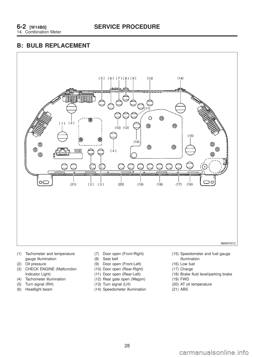
B: BULB REPLACEMENT
B6M0761C
(1) Tachometer and temperature
gauge illumination
(2) Oil pressure
(3) CHECK ENGINE (Malfunction
Indicator Light)
(4) Tachometer illumination
(5) Turn signal (RH)
(6) Headlight beam(7) Door open (Front-Right)
(8) Seat belt
(9) Door open (Front-Left)
(10) Door open (Rear-Right)
(11) Door open (Rear-Left)
(12) Rear gate open (Wagon)
(13) Turn signal (LH)
(14) Speedometer illumination(15) Speedometer and fuel gauge
illumination
(16) Low fuel
(17) Charge
(18) Brake fluid level/parking brake
(19) FWD
(20) AT oil temperature
(21) ABS
28
6-2[W14B0]SERVICE PROCEDURE
14. Combination Meter