1999 SUBARU LEGACY clock
[x] Cancel search: clockPage 165 of 1456
1) Camshaft installation
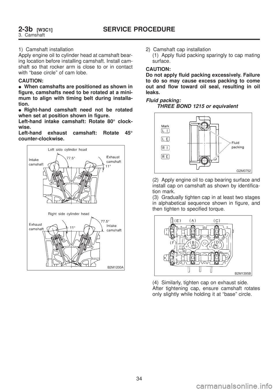
Apply engine oil to cylinder head at camshaft bear-
ing location before installing camshaft. Install cam-
shaft so that rocker arm is close to or in contact
with ªbase circleº of cam lobe.
CAUTION:
IWhen camshafts are positioned as shown in
figure, camshafts need to be rotated at a mini-
mum to align with timing belt during installa-
tion.
IRight-hand camshaft need not be rotated
when set at position shown in figure.
Left-hand intake camshaft: Rotate 80É clock-
wise.
Left-hand exhaust camshaft: Rotate 45É
counter-clockwise.
B2M1200A
2) Camshaft cap installation
(1) Apply fluid packing sparingly to cap mating
surface.
CAUTION:
Do not apply fluid packing excessively. Failure
to do so may cause excess packing to come
out and flow toward oil seal, resulting in oil
leaks.
Fluid packing:
THREE BOND 1215 or equivalent
G2M0752
(2) Apply engine oil to cap bearing surface and
install cap on camshaft as shown by identifica-
tion mark.
(3) Gradually tighten cap in at least two stages
in alphabetical sequence shown in figure, and
then tighten to specified torque.
B2M1395B
(4) Similarly, tighten cap on exhaust side.
After tightening cap, ensure camshaft rotates
only slightly while holding it at ªbaseº circle.
34
2-3b[W3C1]SERVICE PROCEDURE
3. Camshaft
Page 171 of 1456

(5) Put new valve guide, coated with sufficient
oil, in cylinder, and insert ST1 into valve guide.
Press in until the valve guide upper end is flush
with the upper surface of ST2.
ST1 499767200 VALVE GUIDE REMOVER
ST2 498267700 VALVE GUIDE ADJUSTER
B2M1398A
(6) Check the valve guide protrusion.
Valve guide protrusion: L
12.0 Ð 12.4 mm (0.472 Ð 0.488 in)
(7) Ream the inside of valve guide with ST.
Gently rotate the reamer clockwise while press-
ing it lightly into valve guide, and return it also
rotating clockwise. After reaming, clean valve
guide to remove chips.
ST 499767400 VALVE GUIDE REAMER
CAUTION:
IApply engine oil to the reamer when ream-
ing.
IIf the inner surface of the valve guide is torn,
the edge of the reamer should be slightly
ground with an oil stone.
IIf the inner surface of the valve guide
becomes lustrous and the reamer does not
chips, use a new reamer or remedy the reamer.
(8) Recheck the contact condition between
valve and valve seat after replacing valve guide.
4. INTAKE AND EXHAUST VALVE
1) Inspect the flange and stem of valve, and
replace if damaged, worn, or deformed, or if ªHº is
less than the specified limit.
H:
Intake
Standard
1.2 mm (0.047 in)
Limit
0.8 mm (0.031 in)
Exhaust
Standard
1.5 mm (0.059 in)
Limit
0.8 mm (0.031 in))
Valve overall length:
Intake
105.9 mm (4.169 in)
Exhaust
106.2 mm (4.181 in)
G2M0153
2) Put a small amount of grinding compound on
the seat surface and lap the valve and seat sur-
face. Install a new intake valve oil seal after lap-
ping.
40
2-3b[W4C4]SERVICE PROCEDURE
4. Cylinder Head
Page 628 of 1456
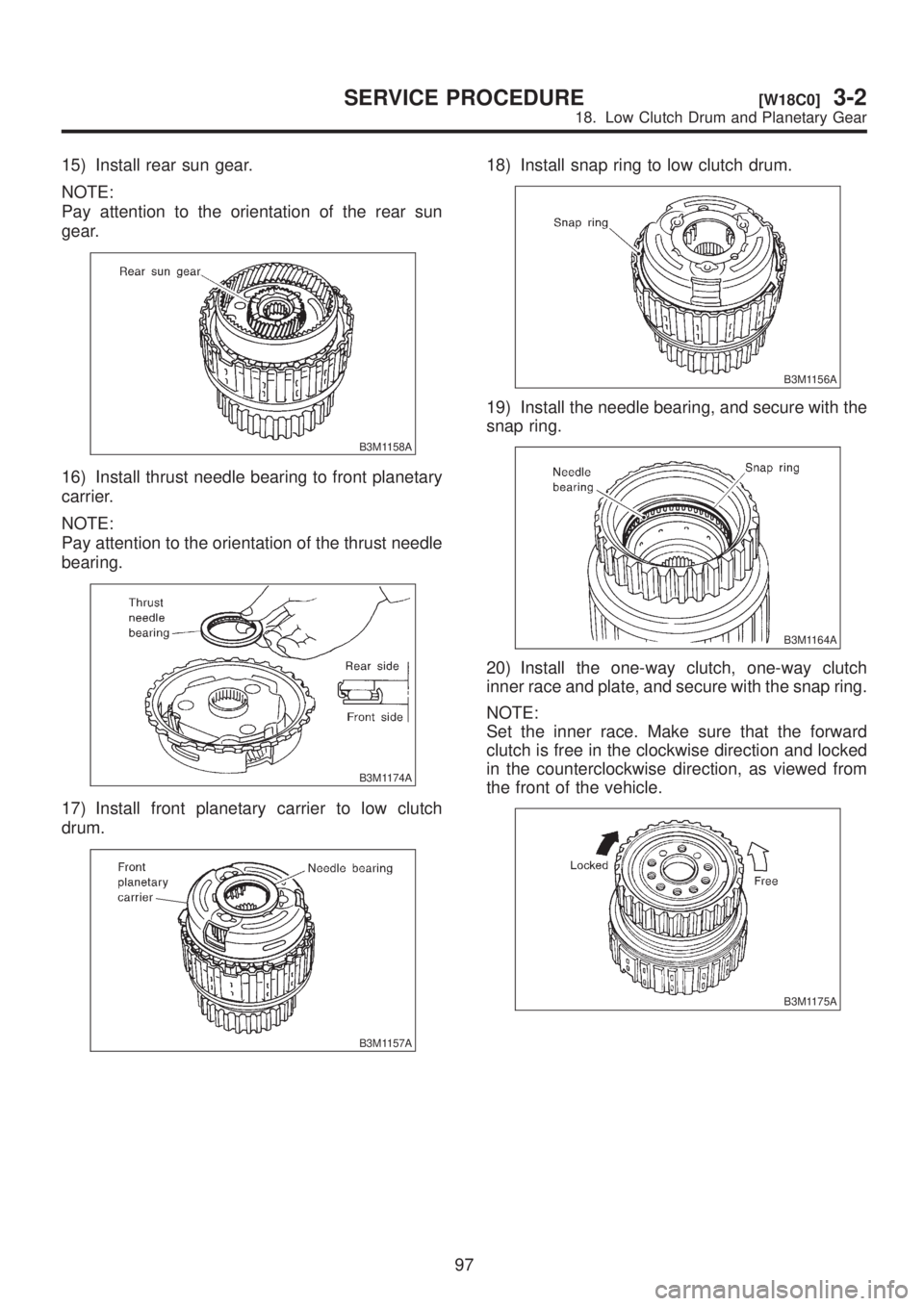
15) Install rear sun gear.
NOTE:
Pay attention to the orientation of the rear sun
gear.
B3M1158A
16) Install thrust needle bearing to front planetary
carrier.
NOTE:
Pay attention to the orientation of the thrust needle
bearing.
B3M1174A
17) Install front planetary carrier to low clutch
drum.
B3M1157A
18) Install snap ring to low clutch drum.
B3M1156A
19) Install the needle bearing, and secure with the
snap ring.
B3M1164A
20) Install the one-way clutch, one-way clutch
inner race and plate, and secure with the snap ring.
NOTE:
Set the inner race. Make sure that the forward
clutch is free in the clockwise direction and locked
in the counterclockwise direction, as viewed from
the front of the vehicle.
B3M1175A
97
[W18C0]3-2SERVICE PROCEDURE
18. Low Clutch Drum and Planetary Gear
Page 711 of 1456
2. CAMBER (FRONT AND REAR)
IInspection
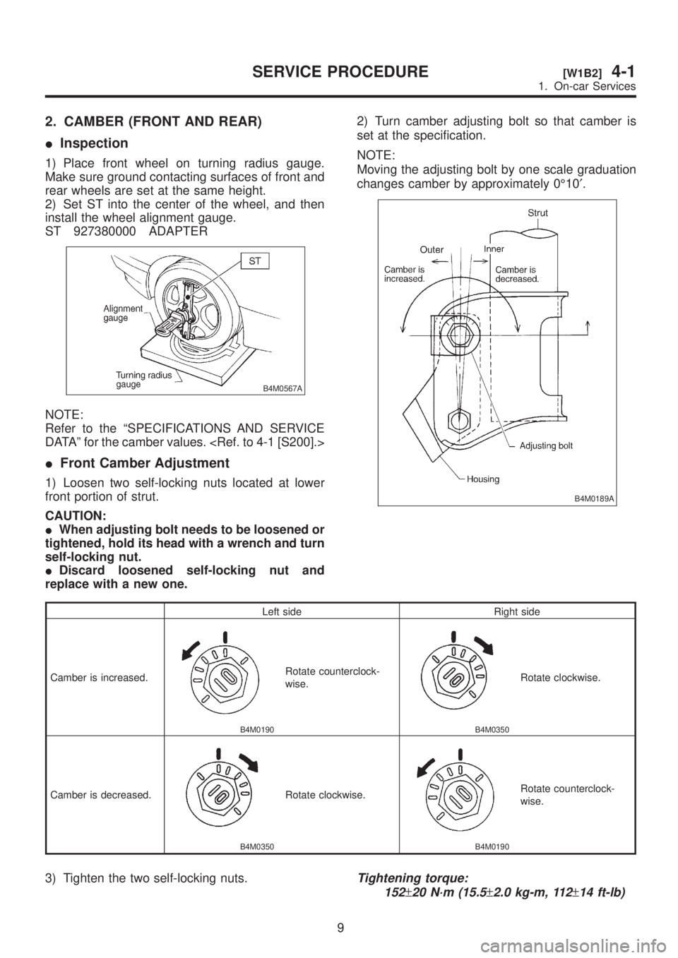
1) Place front wheel on turning radius gauge.
Make sure ground contacting surfaces of front and
rear wheels are set at the same height.
2) Set ST into the center of the wheel, and then
install the wheel alignment gauge.
ST 927380000 ADAPTER
B4M0567A
NOTE:
Refer to the ªSPECIFICATIONS AND SERVICE
DATAº for the camber values.
IFront Camber Adjustment
1) Loosen two self-locking nuts located at lower
front portion of strut.
CAUTION:
IWhen adjusting bolt needs to be loosened or
tightened, hold its head with a wrench and turn
self-locking nut.
IDiscard loosened self-locking nut and
replace with a new one.2) Turn camber adjusting bolt so that camber is
set at the specification.
NOTE:
Moving the adjusting bolt by one scale graduation
changes camber by approximately 0É10¢.
B4M0189A
Left side Right side
Camber is increased.
B4M0190
Rotate counterclock-
wise.
B4M0350
Rotate clockwise.
Camber is decreased.
B4M0350
Rotate clockwise.
B4M0190
Rotate counterclock-
wise.
3) Tighten the two self-locking nuts.Tightening torque:
152
±20 N´m (15.5±2.0 kg-m, 112±14 ft-lb)
9
[W1B2]4-1SERVICE PROCEDURE
1. On-car Services
Page 712 of 1456
3. CASTER (FRONT)
IInspection
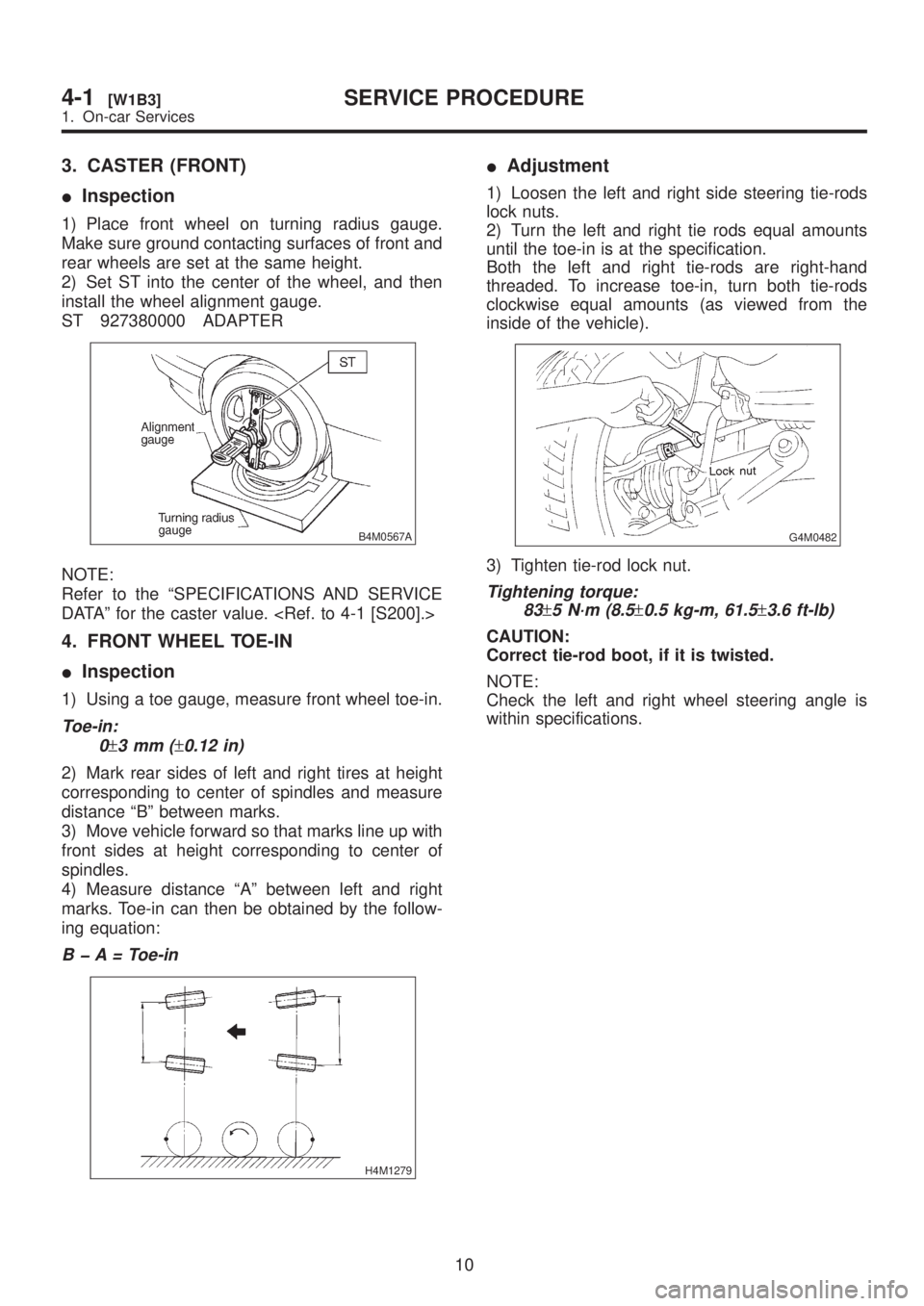
1) Place front wheel on turning radius gauge.
Make sure ground contacting surfaces of front and
rear wheels are set at the same height.
2) Set ST into the center of the wheel, and then
install the wheel alignment gauge.
ST 927380000 ADAPTER
B4M0567A
NOTE:
Refer to the ªSPECIFICATIONS AND SERVICE
DATAº for the caster value.
4. FRONT WHEEL TOE-IN
IInspection
1) Using a toe gauge, measure front wheel toe-in.
Toe-in:
0
±3mm(±0.12 in)
2) Mark rear sides of left and right tires at height
corresponding to center of spindles and measure
distance ªBº between marks.
3) Move vehicle forward so that marks line up with
front sides at height corresponding to center of
spindles.
4) Measure distance ªAº between left and right
marks. Toe-in can then be obtained by the follow-
ing equation:
B þ A = Toe-in
H4M1279
IAdjustment
1) Loosen the left and right side steering tie-rods
lock nuts.
2) Turn the left and right tie rods equal amounts
until the toe-in is at the specification.
Both the left and right tie-rods are right-hand
threaded. To increase toe-in, turn both tie-rods
clockwise equal amounts (as viewed from the
inside of the vehicle).
G4M0482
3) Tighten tie-rod lock nut.
Tightening torque:
83
±5 N´m (8.5±0.5 kg-m, 61.5±3.6 ft-lb)
CAUTION:
Correct tie-rod boot, if it is twisted.
NOTE:
Check the left and right wheel steering angle is
within specifications.
10
4-1[W1B3]SERVICE PROCEDURE
1. On-car Services
Page 713 of 1456
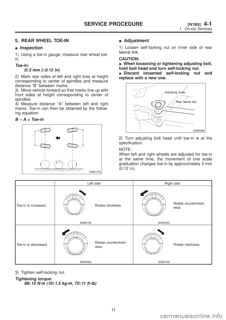
5. REAR WHEEL TOE-IN
IInspection
1) Using a toe-in gauge, measure rear wheel toe-
in.
Toe-in:
0
±3mm(±0.12 in)
2) Mark rear sides of left and right tires at height
corresponding to center of spindles and measure
distance ªBº between marks.
3) Move vehicle forward so that marks line up with
front sides at height corresponding to center of
spindles.
4) Measure distance ªAº between left and right
marks. Toe-in can then be obtained by the follow-
ing equation:
B þ A = Toe-in
H4M1279
IAdjustment
1) Loosen self-locking nut on inner side of rear
lateral link.
CAUTION:
IWhen loosening or tightening adjusting bolt,
hold bolt head and turn self-locking nut.
IDiscard loosened self-locking nut and
replace with a new one.
G4M0486
2) Turn adjusting bolt head until toe-in is at the
specification.
NOTE:
When left and right wheels are adjusted for toe-in
at the same time, the movement of one scale
graduation changes toe-in by approximately 3 mm
(0.12 in).
Left side Right side
Toe-in is increased.
B4M0192
Rotate clockwise.
B4M0352
Rotate counterclock-
wise.
Toe-in is decreased.
B4M0352
Rotate counterclock-
wise.
B4M0192
Rotate clockwise.
3) Tighten self-locking nut.
Tightening torque:
98
±15 N´m (10±1.5 kg-m, 72±11 ft-lb)
11
[W1B5]4-1SERVICE PROCEDURE
1. On-car Services
Page 793 of 1456
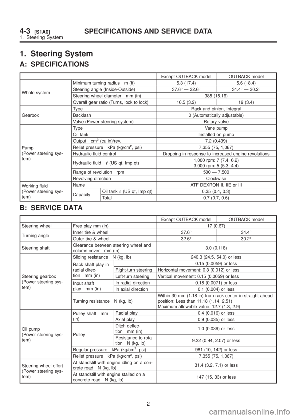
1. Steering System
A: SPECIFICATIONS
Except OUTBACK model OUTBACK model
Whole systemMinimum turning radius m (ft) 5.3 (17.4) 5.6 (18.4)
Steering angle (Inside-Outside) 37.6É Ð 32.6É 34.4É Ð 30.2É
Steering wheel diameter mm (in) 385 (15.16)
Overall gear ratio (Turns, lock to lock) 16.5 (3.2) 19 (3.4)
GearboxType Rack and pinion, Integral
Backlash 0 (Automatically adjustable)
Valve (Power steering system) Rotary valve
Pump
(Power steering sys-
tem)Type Vane pump
Oil tank Installed on pump
Output cm
3(cu in)/rev. 7.2 (0.439)
Relief pressure kPa (kg/cm2, psi) 7,355 (75, 1,067)
Hydraulic fluid control Dropping in response to increased engine revolutions
Hydraulic fluid(US qt, Imp qt)1,000 rpm: 7 (7.4, 6.2)
3,000 rpm: 5 (5.3, 4.4)
Range of revolution rpm 500 Ð 7,500
Revolving direction Clockwise
Working fluid
(Power steering sys-
tem)Name ATF DEXRON II, IIE or III
CapacityOil tank(US qt, Imp qt) 0.35 (0.4, 0.3)
Total 0.7 (0.7, 0.6)
B: SERVICE DATA
Except OUTBACK model OUTBACK model
Steering wheel Free play mm (in) 17 (0.67)
Turning angleInner tire & wheel 37.6É 34.4É
Outer tire & wheel 32.6É 30.2É
Steering shaftClearance between steering wheel and
column cover mm (in)3.0 (0.118)
Steering gearbox
(Power steering sys-
tem)Sliding resistance N (kg, lb) 240.3 (24.5, 54.0) or less
Rack shaft play in
radial direc-
tion mm (in)0.15 (0.0059) or less
Right-turn steering Horizontal movement: 0.3 (0.012) or less
Left-turn steering Vertical movement: 0.15 (0.0059) or less
Input shaft
play mm (in)In radial direction 0.18 (0.0071) or less
In axial direction 0.1 (0.004) or less
Turning resistance N (kg, lb)Within 30 mm (1.18 in) from rack center in straight ahead
position: Less than 11.18 (1.14, 2.51)
Maximum allowable value: 12.7 (1.3, 2.9)
Oil pump
(Power steering sys-
tem)Pulley shaft mm
(in)Radial play 0.4 (0.016) or less
Axial play 0.9 (0.035) or less
PulleyDitch deflec-
tion mm (in)1.0 (0.039) or less
Resistance to rota-
tion N (kg, lb)9.22 (0.94, 2.07) or less
Regular pressure kPa (kg/cm
2, psi) 981 (10, 142) or less
Relief pressure kPa (kg/cm2, psi) 7,355 (75, 1,067)
Steering wheel effort
(Power steering sys-
tem)At standstill with engine idling on a con-
crete road N (kg, lb)31.4 (3.2, 7.1) or less
At standstill with engine stalled on a
concrete road N (kg, lb)147 (15, 33) or less
2
4-3[S1A0]SPECIFICATIONS AND SERVICE DATA
1. Steering System
Page 807 of 1456
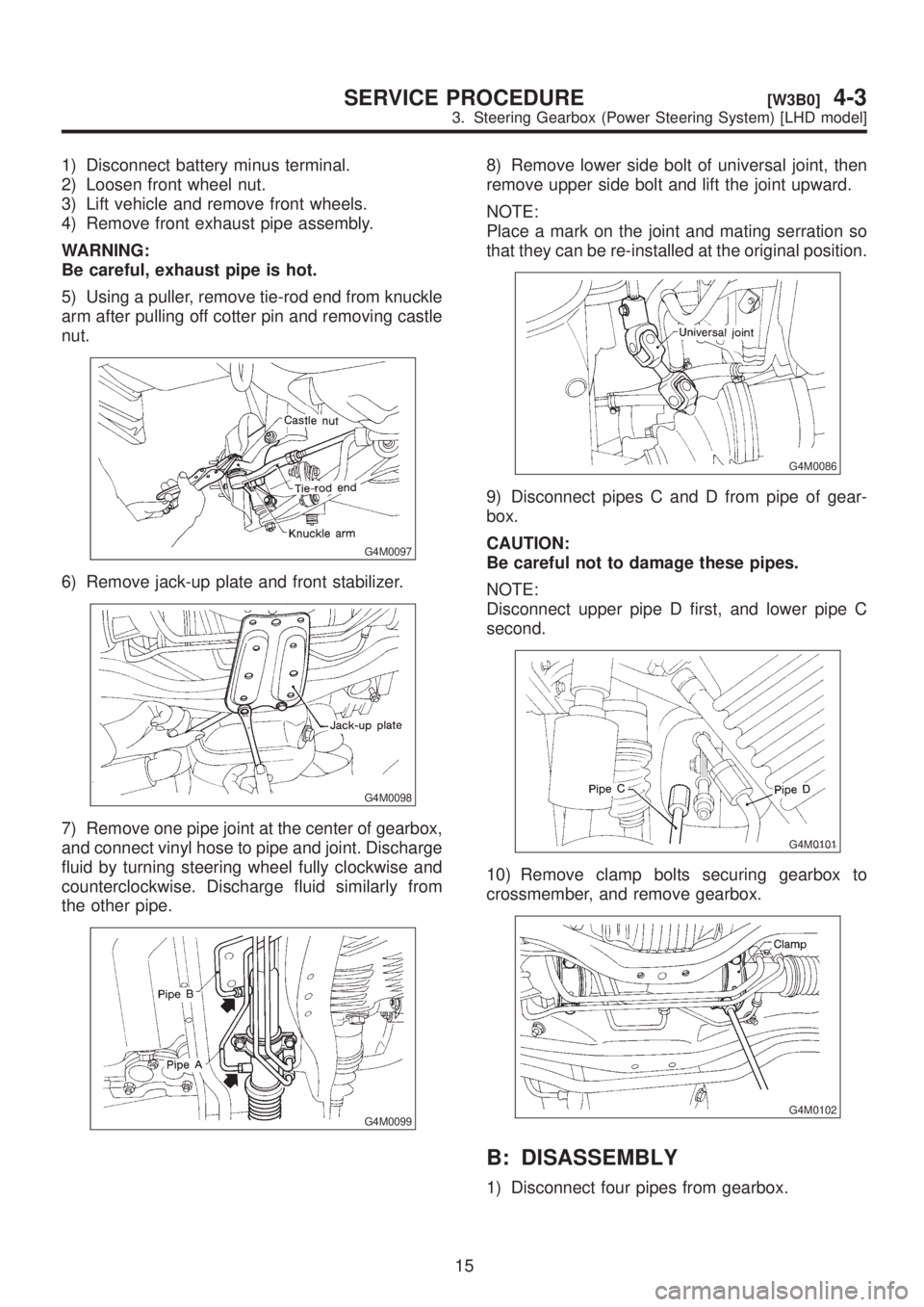
1) Disconnect battery minus terminal.
2) Loosen front wheel nut.
3) Lift vehicle and remove front wheels.
4) Remove front exhaust pipe assembly.
WARNING:
Be careful, exhaust pipe is hot.
5) Using a puller, remove tie-rod end from knuckle
arm after pulling off cotter pin and removing castle
nut.
G4M0097
6) Remove jack-up plate and front stabilizer.
G4M0098
7) Remove one pipe joint at the center of gearbox,
and connect vinyl hose to pipe and joint. Discharge
fluid by turning steering wheel fully clockwise and
counterclockwise. Discharge fluid similarly from
the other pipe.
G4M0099
8) Remove lower side bolt of universal joint, then
remove upper side bolt and lift the joint upward.
NOTE:
Place a mark on the joint and mating serration so
that they can be re-installed at the original position.
G4M0086
9) Disconnect pipes C and D from pipe of gear-
box.
CAUTION:
Be careful not to damage these pipes.
NOTE:
Disconnect upper pipe D first, and lower pipe C
second.
G4M0101
10) Remove clamp bolts securing gearbox to
crossmember, and remove gearbox.
G4M0102
B: DISASSEMBLY
1) Disconnect four pipes from gearbox.
15
[W3B0]4-3SERVICE PROCEDURE
3. Steering Gearbox (Power Steering System) [LHD model]