1999 SUBARU LEGACY clock
[x] Cancel search: clockPage 844 of 1456
4) If steering body, valve housing or pinion and
valve is replaced with a new one, add two or three
shims, install valve on pinion housing and tighten
with two bolts to 25±5 N´m (2.5±0.5 kg-m, 18.1±3.6
ft-lb). Then, measure clearance between steering
body and valve housing using a thickness gauge.
Remove shims so that the clearance is zero.
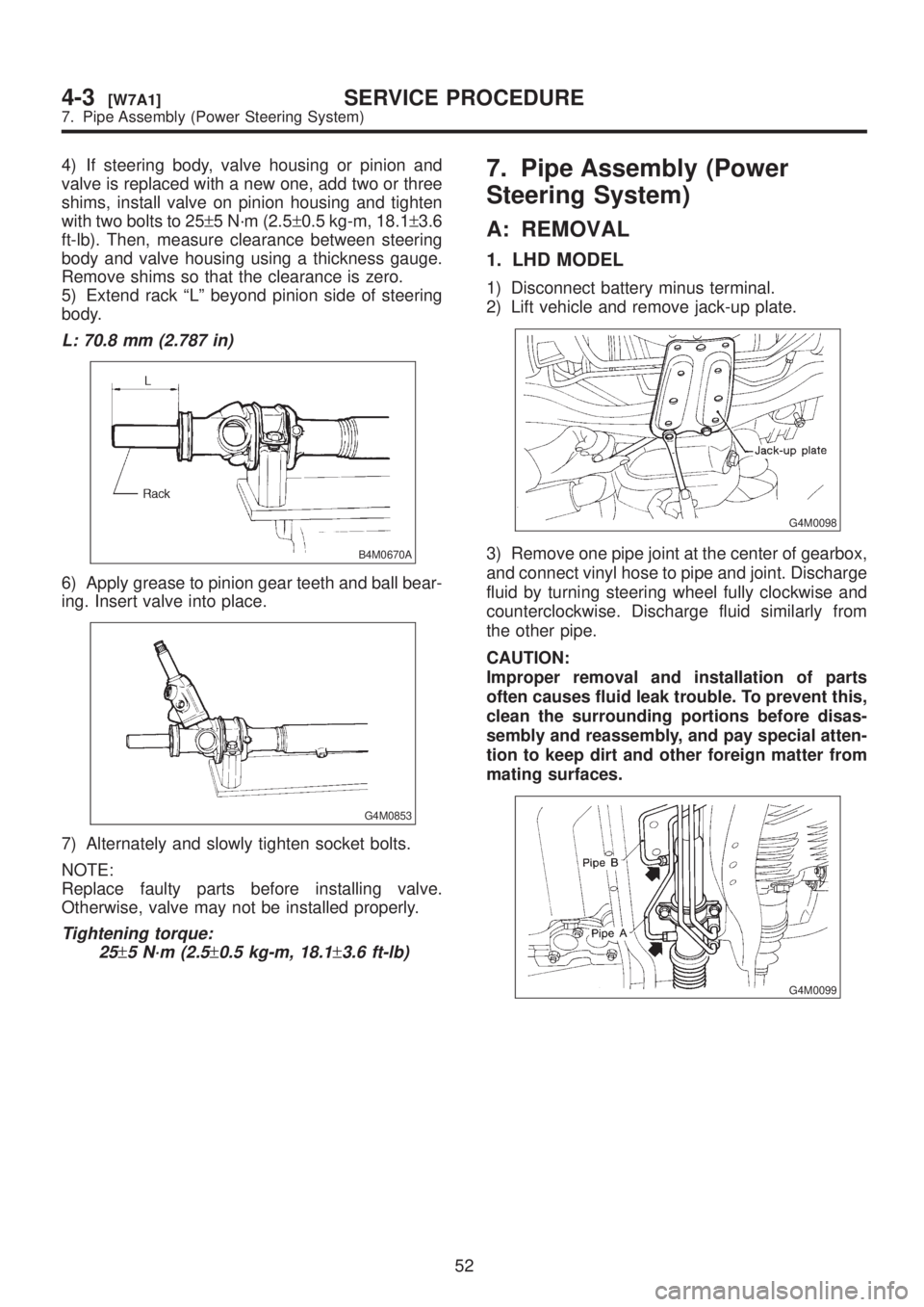
5) Extend rack ªLº beyond pinion side of steering
body.
L: 70.8 mm (2.787 in)
B4M0670A
6) Apply grease to pinion gear teeth and ball bear-
ing. Insert valve into place.
G4M0853
7) Alternately and slowly tighten socket bolts.
NOTE:
Replace faulty parts before installing valve.
Otherwise, valve may not be installed properly.
Tightening torque:
25
±5 N´m (2.5±0.5 kg-m, 18.1±3.6 ft-lb)
7. Pipe Assembly (Power
Steering System)
A: REMOVAL
1. LHD MODEL
1) Disconnect battery minus terminal.
2) Lift vehicle and remove jack-up plate.
G4M0098
3) Remove one pipe joint at the center of gearbox,
and connect vinyl hose to pipe and joint. Discharge
fluid by turning steering wheel fully clockwise and
counterclockwise. Discharge fluid similarly from
the other pipe.
CAUTION:
Improper removal and installation of parts
often causes fluid leak trouble. To prevent this,
clean the surrounding portions before disas-
sembly and reassembly, and pay special atten-
tion to keep dirt and other foreign matter from
mating surfaces.
G4M0099
52
4-3[W7A1]SERVICE PROCEDURE
7. Pipe Assembly (Power Steering System)
Page 845 of 1456
4) If steering body, valve housing or pinion and
valve is replaced with a new one, add two or three
shims, install valve on pinion housing and tighten
with two bolts to 25±5 N´m (2.5±0.5 kg-m, 18.1±3.6
ft-lb). Then, measure clearance between steering
body and valve housing using a thickness gauge.
Remove shims so that the clearance is zero.
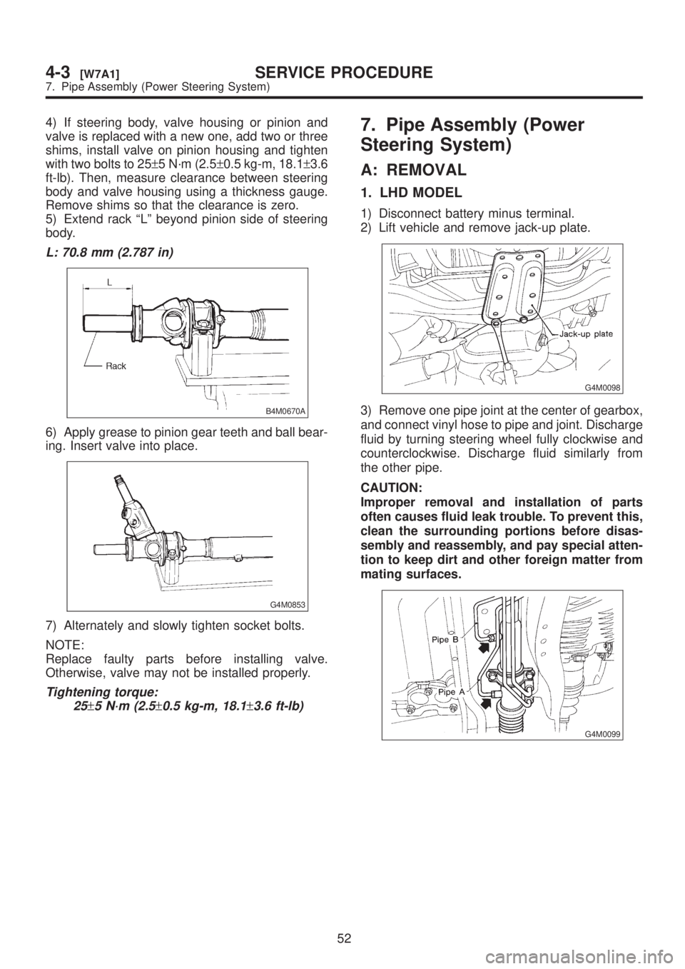
5) Extend rack ªLº beyond pinion side of steering
body.
L: 70.8 mm (2.787 in)
B4M0670A
6) Apply grease to pinion gear teeth and ball bear-
ing. Insert valve into place.
G4M0853
7) Alternately and slowly tighten socket bolts.
NOTE:
Replace faulty parts before installing valve.
Otherwise, valve may not be installed properly.
Tightening torque:
25
±5 N´m (2.5±0.5 kg-m, 18.1±3.6 ft-lb)
7. Pipe Assembly (Power
Steering System)
A: REMOVAL
1. LHD MODEL
1) Disconnect battery minus terminal.
2) Lift vehicle and remove jack-up plate.
G4M0098
3) Remove one pipe joint at the center of gearbox,
and connect vinyl hose to pipe and joint. Discharge
fluid by turning steering wheel fully clockwise and
counterclockwise. Discharge fluid similarly from
the other pipe.
CAUTION:
Improper removal and installation of parts
often causes fluid leak trouble. To prevent this,
clean the surrounding portions before disas-
sembly and reassembly, and pay special atten-
tion to keep dirt and other foreign matter from
mating surfaces.
G4M0099
52
4-3[W7A1]SERVICE PROCEDURE
7. Pipe Assembly (Power Steering System)
Page 847 of 1456
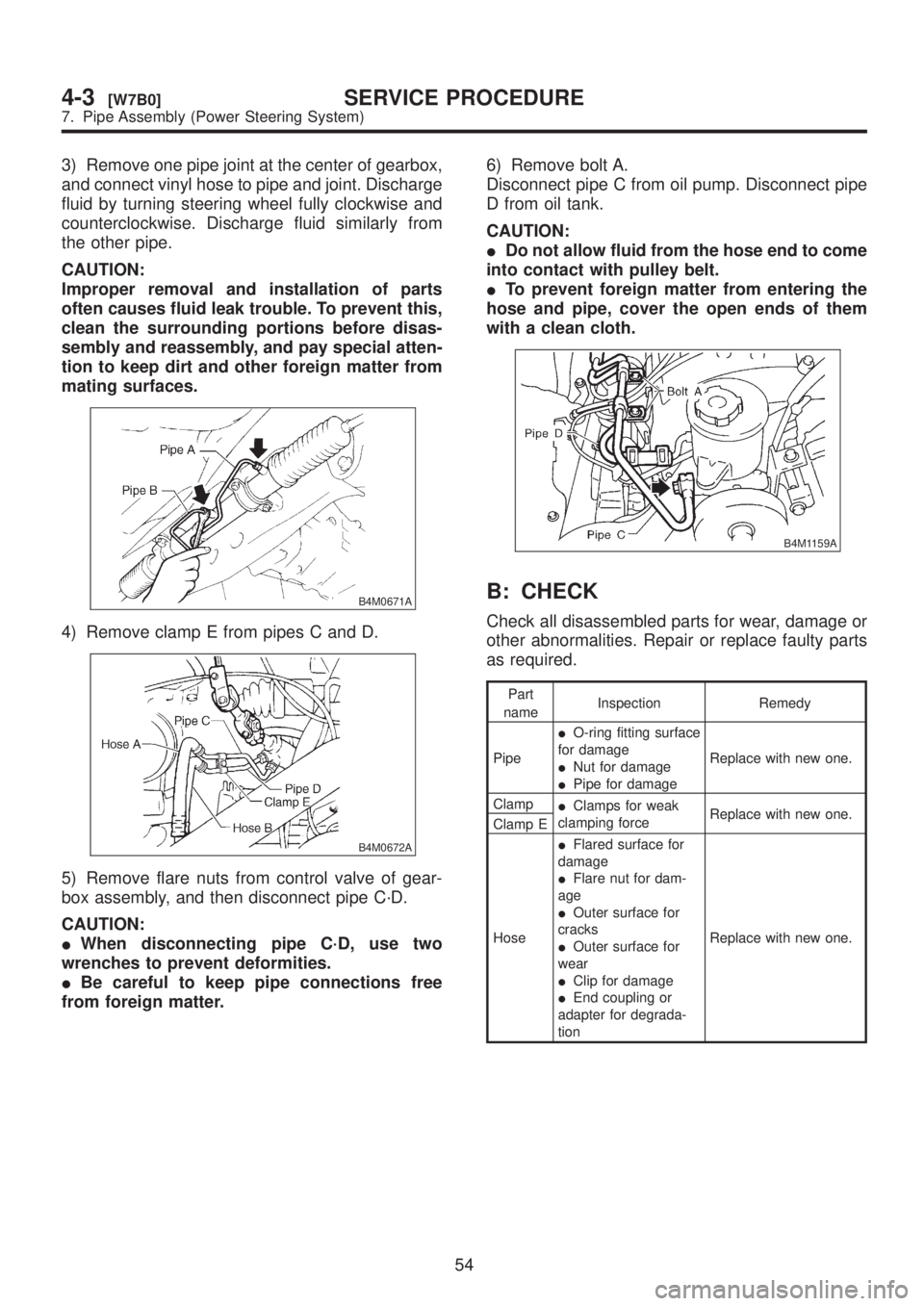
3) Remove one pipe joint at the center of gearbox,
and connect vinyl hose to pipe and joint. Discharge
fluid by turning steering wheel fully clockwise and
counterclockwise. Discharge fluid similarly from
the other pipe.
CAUTION:
Improper removal and installation of parts
often causes fluid leak trouble. To prevent this,
clean the surrounding portions before disas-
sembly and reassembly, and pay special atten-
tion to keep dirt and other foreign matter from
mating surfaces.
B4M0671A
4) Remove clamp E from pipes C and D.
B4M0672A
5) Remove flare nuts from control valve of gear-
box assembly, and then disconnect pipe C´D.
CAUTION:
IWhen disconnecting pipe C´D, use two
wrenches to prevent deformities.
IBe careful to keep pipe connections free
from foreign matter.6) Remove bolt A.
Disconnect pipe C from oil pump. Disconnect pipe
D from oil tank.
CAUTION:
IDo not allow fluid from the hose end to come
into contact with pulley belt.
ITo prevent foreign matter from entering the
hose and pipe, cover the open ends of them
with a clean cloth.
B4M1159A
B: CHECK
Check all disassembled parts for wear, damage or
other abnormalities. Repair or replace faulty parts
as required.
Part
nameInspection Remedy
PipeIO-ring fitting surface
for damage
INut for damage
IPipe for damageReplace with new one.
Clamp
IClamps for weak
clamping forceReplace with new one.
Clamp E
HoseIFlared surface for
damage
IFlare nut for dam-
age
IOuter surface for
cracks
IOuter surface for
wear
IClip for damage
IEnd coupling or
adapter for degrada-
tionReplace with new one.
54
4-3[W7B0]SERVICE PROCEDURE
7. Pipe Assembly (Power Steering System)
Page 953 of 1456
B: REMOVAL
1. ACCELERATOR PEDAL
1) Disconnect ground cable from battery.
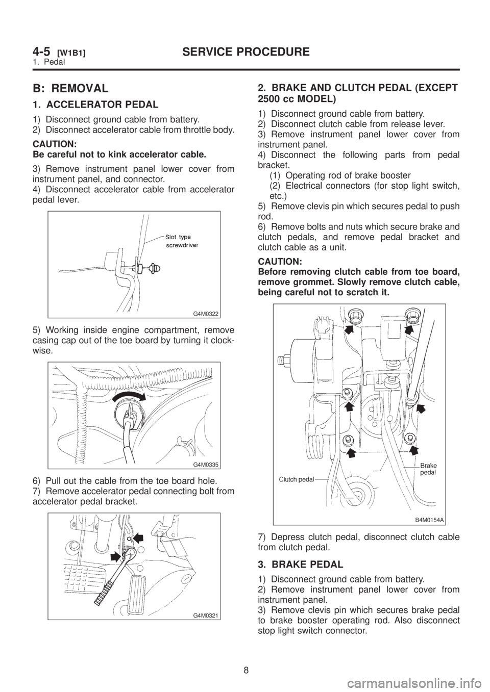
2) Disconnect accelerator cable from throttle body.
CAUTION:
Be careful not to kink accelerator cable.
3) Remove instrument panel lower cover from
instrument panel, and connector.
4) Disconnect accelerator cable from accelerator
pedal lever.
G4M0322
5) Working inside engine compartment, remove
casing cap out of the toe board by turning it clock-
wise.
G4M0335
6) Pull out the cable from the toe board hole.
7) Remove accelerator pedal connecting bolt from
accelerator pedal bracket.
G4M0321
2. BRAKE AND CLUTCH PEDAL (EXCEPT
2500 cc MODEL)
1) Disconnect ground cable from battery.
2) Disconnect clutch cable from release lever.
3) Remove instrument panel lower cover from
instrument panel.
4) Disconnect the following parts from pedal
bracket.
(1) Operating rod of brake booster
(2) Electrical connectors (for stop light switch,
etc.)
5) Remove clevis pin which secures pedal to push
rod.
6) Remove bolts and nuts which secure brake and
clutch pedals, and remove pedal bracket and
clutch cable as a unit.
CAUTION:
Before removing clutch cable from toe board,
remove grommet. Slowly remove clutch cable,
being careful not to scratch it.
B4M0154A
7) Depress clutch pedal, disconnect clutch cable
from clutch pedal.
3. BRAKE PEDAL
1) Disconnect ground cable from battery.
2) Remove instrument panel lower cover from
instrument panel.
3) Remove clevis pin which secures brake pedal
to brake booster operating rod. Also disconnect
stop light switch connector.
8
4-5[W1B1]SERVICE PROCEDURE
1. Pedal
Page 959 of 1456
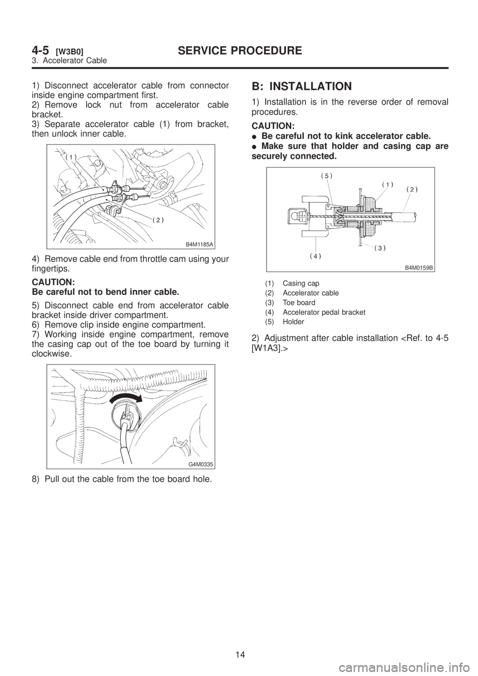
1) Disconnect accelerator cable from connector
inside engine compartment first.
2) Remove lock nut from accelerator cable
bracket.
3) Separate accelerator cable (1) from bracket,
then unlock inner cable.
B4M1185A
4) Remove cable end from throttle cam using your
fingertips.
CAUTION:
Be careful not to bend inner cable.
5) Disconnect cable end from accelerator cable
bracket inside driver compartment.
6) Remove clip inside engine compartment.
7) Working inside engine compartment, remove
the casing cap out of the toe board by turning it
clockwise.
G4M0335
8) Pull out the cable from the toe board hole.
B: INSTALLATION
1) Installation is in the reverse order of removal
procedures.
CAUTION:
IBe careful not to kink accelerator cable.
IMake sure that holder and casing cap are
securely connected.
B4M0159B
(1) Casing cap
(2) Accelerator cable
(3) Toe board
(4) Accelerator pedal bracket
(5) Holder
2) Adjustment after cable installation
14
4-5[W3B0]SERVICE PROCEDURE
3. Accelerator Cable
Page 1177 of 1456
![SUBARU LEGACY 1999 Service Repair Manual 6. Combination Switch
A: REMOVAL
1) Turn ignition switch off.
2) Disconnect ground cable from battery and wait
for at least 20 seconds before starting work.
3) Remove lower cover. <Ref. to 5-4 [W1A0]. SUBARU LEGACY 1999 Service Repair Manual 6. Combination Switch
A: REMOVAL
1) Turn ignition switch off.
2) Disconnect ground cable from battery and wait
for at least 20 seconds before starting work.
3) Remove lower cover. <Ref. to 5-4 [W1A0].](/manual-img/17/57435/w960_57435-1176.png)
6. Combination Switch
A: REMOVAL
1) Turn ignition switch off.
2) Disconnect ground cable from battery and wait
for at least 20 seconds before starting work.
3) Remove lower cover.
Disconnect airbag connector (AB3) and (AB8)
below steering column.
CAUTION:
Do not reconnect airbag connector at steering
column until combination switch is securely re-
installed.
G5M0312
4) Disconnect combination switch connectors
from body harness connector.
5) Set front wheels in straight ahead position.
Using TORX
TBIT T30, remove two TORXTbolts.
H5M0662A
6) Disconnect airbag connector on back of airbag
module.
module, and place it with pad side facing upward.
H5M0664
7) Using steering puller, remove steering wheel.
CAUTION:
Do not allow connector to interfere when
removing steering wheel.
G5M0332
8) Remove steering column covers.
9) Removing two retaining screws, remove combi-
nation switch.
B5M0106
B: ADJUSTMENT
1. CENTERING ROLL CONNECTOR
Before installing steering wheel, make sure to cen-
ter roll connector built into combination switch.
1) Make sure that front wheels are positioned
straight ahead.
2) Install steering gearbox, steering shaft and
combination switch properly. Turn roll connector
pin (A) clockwise until it stops.
3) Then, back off roll connector pin (A) approxi-
mately 2.65 turns until ªGº marks aligned.
B5M0457A
15
[W6B1]5-5SERVICE PROCEDURE
6. Combination Switch
Page 1183 of 1456
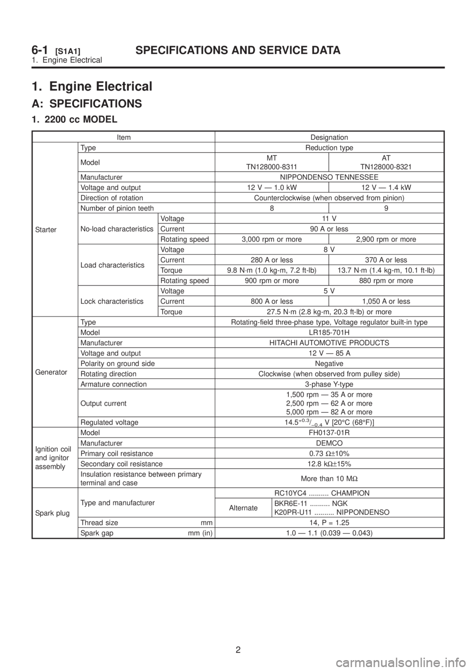
1. Engine Electrical
A: SPECIFICATIONS
1. 2200 cc MODEL
Item Designation
StarterType Reduction type
ModelMT
TN128000-8311AT
TN128000-8321
Manufacturer NIPPONDENSO TENNESSEE
Voltage and output 12 V Ð 1.0 kW 12 V Ð 1.4 kW
Direction of rotation Counterclockwise (when observed from pinion)
Number of pinion teeth 8 9
No-load characteristicsVoltage 11 V
Current 90 A or less
Rotating speed 3,000 rpm or more 2,900 rpm or more
Load characteristicsVoltage 8 V
Current 280 A or less 370 A or less
Torque 9.8 N´m (1.0 kg-m, 7.2 ft-lb) 13.7 N´m (1.4 kg-m, 10.1 ft-lb)
Rotating speed 900 rpm or more 880 rpm or more
Lock characteristicsVoltage 5 V
Current 800 A or less 1,050 A or less
Torque 27.5 N´m (2.8 kg-m, 20.3 ft-lb) or more
GeneratorType Rotating-field three-phase type, Voltage regulator built-in type
Model LR185-701H
Manufacturer HITACHI AUTOMOTIVE PRODUCTS
Voltage and output 12VÐ85A
Polarity on ground side Negative
Rotating direction Clockwise (when observed from pulley side)
Armature connection 3-phase Y-type
Output current1,500 rpm Ð 35 A or more
2,500 rpm Ð 62 A or more
5,000 rpm Ð 82 A or more
Regulated voltage 14.5
+0.3/þ0.4V [20ÉC (68ÉF)]
Ignition coil
and ignitor
assemblyModel FH0137-01R
Manufacturer DEMCO
Primary coil resistance 0.73W±10%
Secondary coil resistance 12.8 kW±15%
Insulation resistance between primary
terminal and caseMore than 10 MW
Spark plugType and manufacturerRC10YC4 .......... CHAMPION
AlternateBKR6E-11 .......... NGK
K20PR-U11 .......... NIPPONDENSO
Thread size mm 14, P = 1.25
Spark gap mm (in) 1.0 Ð 1.1 (0.039 Ð 0.043)
2
6-1[S1A1]SPECIFICATIONS AND SERVICE DATA
1. Engine Electrical
Page 1184 of 1456
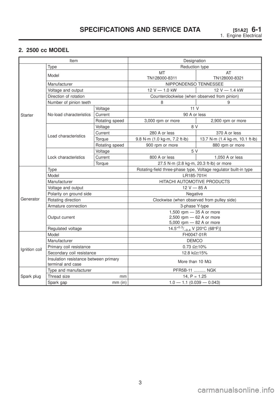
2. 2500 cc MODEL
Item Designation
StarterType Reduction type
ModelMT
TN128000-8311AT
TN128000-8321
Manufacturer NIPPONDENSO TENNESSEE
Voltage and output 12 V Ð 1.0 kW 12 V Ð 1.4 kW
Direction of rotation Counterclockwise (when observed from pinion)
Number of pinion teeth 8 9
No-load characteristicsVoltage 11 V
Current 90 A or less
Rotating speed 3,000 rpm or more 2,900 rpm or more
Load characteristicsVoltage 8 V
Current 280 A or less 370 A or less
Torque 9.8 N´m (1.0 kg-m, 7.2 ft-lb) 13.7 N´m (1.4 kg-m, 10.1 ft-lb)
Rotating speed 900 rpm or more 880 rpm or more
Lock characteristicsVoltage 5 V
Current 800 A or less 1,050 A or less
Torque 27.5 N´m (2.8 kg-m, 20.3 ft-lb) or more
GeneratorType Rotating-field three-phase type, Voltage regulator built-in type
Model LR185-701H
Manufacturer HITACHI AUTOMOTIVE PRODUCTS
Voltage and output 12VÐ85A
Polarity on ground side Negative
Rotating direction Clockwise (when observed from pulley side)
Armature connection 3-phase Y-type
Output current1,500 rpm Ð 35 A or more
2,500 rpm Ð 62 A or more
5,000 rpm Ð 82 A or more
Regulated voltage 14.5
+0.3/þ0.4V [20ÉC (68ÉF)]
Ignition coilModel FH0047-01R
Manufacturer DEMCO
Primary coil resistance 0.73W±10%
Secondary coil resistance 12.8 kW±15%
Insulation resistance between primary
terminal and caseMore than 10 MW
Spark plugType and manufacturer PFR5B-11 .......... NGK
Thread size mm 14, P = 1.25
Spark gap mm (in) 1.0 Ð 1.1 (0.039 Ð 0.043)
3
[S1A2]6-1SPECIFICATIONS AND SERVICE DATA
1. Engine Electrical