Page 563 of 1456
5. Duty Solenoid C and
Transfer Valve Body
A: REMOVAL
1) Remove air intake duct and chamber. (Except
2200 cc California spec. vehicles)
S6M0007
2) Remove air intake duct and cleaner case.
(2200 cc California spec. vehicles)
and
B2M2320
3) Remove pitching stopper.
B3M1042
4) Raise vehicle and drain ATF.
B3M1036A
5) Remove front exhaust pipe and center exhaust
pipe.
Disconnect oxygen sensor connector, and remove
exhaust pipe.
and
G3M0305
6) Remove propeller shaft.
NOTE:
Before removing propeller shaft, scribe matching
marks on propeller shaft and rear differential cou-
pling.
G3M0782
37
[W5A0]3-2SERVICE PROCEDURE
5. Duty Solenoid C and Transfer Valve Body
Page 564 of 1456
7) Remove rear crossmember.
(1) Support transmission using a transmission
jack and raise slightly.
(2) Remove bolts and nuts as shown in Figure.
S2M0221
8) Remove vehicle speed sensor 1 (rear).
B3M1043
9) Remove extension and gasket.
(1) Remove select cable nut.
G3M0308
(2) Move gear select cable so that extension
bolts can be removed.
(3) Remove bolts.(4) Remove extension case.
NOTE:
Use a container to catch oil flowing from extension.
B3M1044
10) Disconnect duty solenoid C (transfer) connec-
tor.
11) Remove duty solenoid C (transfer) and trans-
fer valve body.
B3M1045A
B: INSTALLATION
1) Install duty solenoid C and transfer valve body.
(1) Install duty solenoid C and transfer valve
body.
Tightening torque:
T: 8
±1 N´m (0.8±0.1 kg-m, 5.8±0.7 ft-lb)
(2) Connect duty solenoid C (transfer) connec-
tor.
B3M1045B
38
3-2[W5B0]SERVICE PROCEDURE
5. Duty Solenoid C and Transfer Valve Body
Page 565 of 1456
2) Install extension case to transmission case.
(1) Tighten 11 bolts.
Tightening torque:
25
±2 N´m (2.5±0.2 kg-m, 18.1±1.4 ft-lb)
(2) Install select cable.
Tightening torque:
14
±4 N´m (1.4±0.4 kg-m, 10.1±2.9 ft-lb)
G3M0308
3) Install vehicle speed sensor 1 (rear).
Tightening torque:
T: 7
±1 N´m (0.7±0.1 kg-m, 5.1±0.7 ft-lb)
B3M1043A
4) Install rear crossmember.
(1) Tighten bolts.
Tightening torque:
T1: 37
±10 N´m (3.8±1.0 kg-m, 27±7 ft-lb)
T2: 69
±15 N´m (7.0±1.5 kg-m, 51±11 ft-lb)
S2M0221B
(2) Lower and remove transmission jack.5) Install propeller shaft.
NOTE:
Align matching marks on propeller shaft and rear
differential coupling.
G3M0782
6) Install front exhaust pipe and center exhaust
pipe.
and
G3M0305
7) Lower and remove jack.
8) Connect the following parts:
(1) Oxygen sensor connector
(2) Transmission harness connector
S2M0212A
39
[W5B0]3-2SERVICE PROCEDURE
5. Duty Solenoid C and Transfer Valve Body
Page 570 of 1456

stall speed range on the tachometer scale.
3) Place the wheel chocks at the front and rear of
all wheels and engage the parking brake.
4) Move the manual linkage to ensure it operates
properly, and shift the select lever to the 2 range.
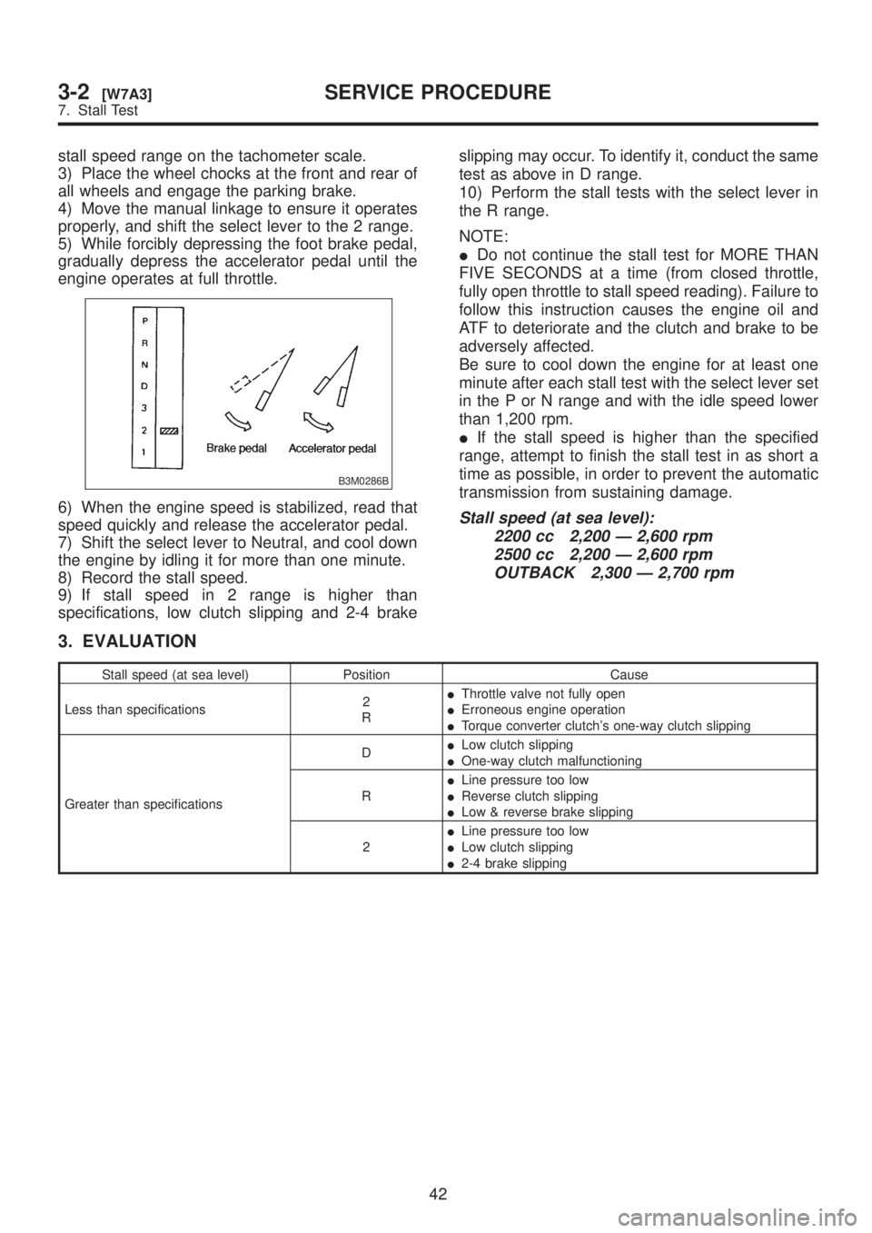
5) While forcibly depressing the foot brake pedal,
gradually depress the accelerator pedal until the
engine operates at full throttle.
B3M0286B
6) When the engine speed is stabilized, read that
speed quickly and release the accelerator pedal.
7) Shift the select lever to Neutral, and cool down
the engine by idling it for more than one minute.
8) Record the stall speed.
9) If stall speed in 2 range is higher than
specifications, low clutch slipping and 2-4 brakeslipping may occur. To identify it, conduct the same
test as above in D range.
10) Perform the stall tests with the select lever in
the R range.
NOTE:
IDo not continue the stall test for MORE THAN
FIVE SECONDS at a time (from closed throttle,
fully open throttle to stall speed reading). Failure to
follow this instruction causes the engine oil and
ATF to deteriorate and the clutch and brake to be
adversely affected.
Be sure to cool down the engine for at least one
minute after each stall test with the select lever set
in the P or N range and with the idle speed lower
than 1,200 rpm.
IIf the stall speed is higher than the specified
range, attempt to finish the stall test in as short a
time as possible, in order to prevent the automatic
transmission from sustaining damage.Stall speed (at sea level):
2200 cc 2,200 Ð 2,600 rpm
2500 cc 2,200 Ð 2,600 rpm
OUTBACK 2,300 Ð 2,700 rpm
3. EVALUATION
Stall speed (at sea level) Position Cause
Less than specifications2
RIThrottle valve not fully open
IErroneous engine operation
ITorque converter clutch's one-way clutch slipping
Greater than specificationsDILow clutch slipping
IOne-way clutch malfunctioning
RILine pressure too low
IReverse clutch slipping
ILow & reverse brake slipping
2ILine pressure too low
ILow clutch slipping
I2-4 brake slipping
42
3-2[W7A3]SERVICE PROCEDURE
7. Stall Test
Page 577 of 1456

10) Remove the oil cooler inlet and outlet pipes.
CAUTION:
When removing outlet pipes, be careful not to
lose balls and springs used with retaining
screws.
B3M1053A
2. SEPARATION OF EACH SECTION
1) Separation of torque converter clutch case and
transmission case sections
CAUTION:
IBe careful not to damage the oil seal and
bushing inside the torque converter clutch
case by the oil pump cover.
IBe careful not to lose the rubber seal.
NOTE:
Separate these cases while tapping lightly on the
housing.
B3M1055A
2) Separation of transmission case and extension
sections
(1) Remove vehicle speed sensor 1 (rear).
B3M1056A
(2) Separation of transmission case and exten-
sion case sections
B3M1057A
3. TRANSMISSION CASE SECTION
1) Remove the reduction driven gear.
(1) Straighten the staked portion, and remove
the lock nut.
NOTE:
Set the range selector lever to ªPº.
B3M1058A
(2) Using the ST1 and ST2, extract the reduc-
tion driven gear.
NOTE:
ST1 499737000 PULLER
ST2 899524100 PULLER SET
B3M0954A
48
3-2[W11B2]SERVICE PROCEDURE
11. Overall Transmission
Page 578 of 1456
(3) Using the ST, extract the reduction drive
gear.
ST 499737100 PULLER SET
B3M0953A
2) Remove transfer valve body and duty solenoid
C (Transfer).
(1) Disconnect connector from duty solenoid C
(Transfer).
(2) Remove transfer valve body and duty sole-
noid C (Transfer).
B2M2264
(3) Pull out inlet filter
B3M1061A
3) Remove the parking pawl, return spring and
shaft.
B3M1062A
4) Loosen the taper roller bearing mounting bolts.
B3M1063
5) Place two wooden blocks on the workbench,
and stand the transmission case with its rear end
facing down.
CAUTION:
IBe careful not to scratch the rear mating sur-
face of the transmission case.
INote that the parking rod and drive pinion
protrude from the mating surface.
B3M1064A
49
[W11B3]3-2SERVICE PROCEDURE
11. Overall Transmission
Page 583 of 1456

34) Remove parking support.
B3M1088A
4. TORQUE CONVERTER CLUTCH CASE
SECTION
1) Wrap the axle shaft serration with vinyl tape.
G3M0368
2) Remove the differential side retainer with ST.
CAUTION:
Hold the differential case assembly by hand to
avoid damaging retainer mounting hole of the
torque converter clutch case and speedometer
gears.
ST 499787000 WRENCH ASSY
3) Extract the axle shaft with ST1 and ST2.
CAUTION:
Do not reuse the circlip.
ST1 499095500 REMOVER
ST2 499247300 INSTALLER
G3M0956
4) Remove the differential case assembly.
CAUTION:
IRemove the seal pipe if it is attached. (Reus-
ing is not allowed.)
IBe careful not to damage the retainer mount-
ing hole of the torque converter clutch case
and the speedometer gears.
G3M0370
5. EXTENSION SECTION
1) Take out the transfer clutch by lightly tapping
the end of the rear drive shaft.
CAUTION:
Be careful not to damage the oil seal in the
extension.
B3M1089A
2) Remove the transfer pipe.
CAUTION:
Be careful not to bend the pipe.
B3M1090A
54
3-2[W11B4]SERVICE PROCEDURE
11. Overall Transmission
Page 591 of 1456

(1) Using a press and ST1, install the needle
bearing to the inner race.
ST1 398497701 INSTALLER
NOTE:
Use the following ST when removing.
ST 398527700 PULLER ASSY
B3M1409A
(2) Install two seal rings to one-way clutch inner
race.
NOTE:
Apply vaseline to the groove of the inner race and
to the seal ring after installation, so that the seal
ring will not expand.
B3M1100A
(3) Tighten eight socket head bolts from the
rear side of the transmission case.
Tightening torque:
25
±2 N´m (2.5±0.2 kg-m, 18.1±1.4 ft-lb)
CAUTION:
Be sure to tighten evenly.
B3M0958
(4) Install thrust needle bearing.NOTE:
Place transmission case with the front facing up.
12) Installation of the low & reverse brake:
(1) Install dish plate, driven plates, drive plates,
and a retaining plate, and secure with a snap
ring.
NOTE:
Pay attention to the orientation of the dish plate.
B3M1081A
(2) Apply compressed air intermittently to
check for operation.
B3M0957
(3) Check the clearance. (Selection of retaining
plate)
NOTE:
Before measuring clearance, place the same thick-
ness of shim on both sides to prevent retaining
plate from tilting.
Standard value:
0.7 Ð 1.2 mm (0.028 Ð 0.047 in)
Allowable limit:
2.2 mm (0.087 in)
B3M0977
62
3-2[W11C2]SERVICE PROCEDURE
11. Overall Transmission