1999 SUBARU LEGACY engine oil
[x] Cancel search: engine oilPage 835 of 1456
boots toward tie-rod end side, respectively, with the
gearbox mounted to the vehicle, and remove oil
from the surrounding portions. Then, turn the steer-
ing wheel from lock to lock 30 to 40 times with the
engine running, then make comparison of the
leaked portion immediately after and several hours
after this operation.
6) Leakage from ªeº
There are two possible causes. Take following step
first. Remove the pipe assembly B from the valve
housing, and close the circuit with ST.
ST 926420000 PLUG
Turn the steering wheel from lock to lock 30 to 40
times with the engine running, then make compari-
son of the leaked portion between immediately
after and several hours after this operation.
CAUTION:
IIf leakage from ªeº is noted again:
The oil seal of pinion and valve assembly is
damaged. Replace pinion and valve assembly
with a new one. Or replace the oil seal and the
parts that are damaged during disassembly
with new ones.
IIf oil stops leaking from ªeº:
The oil seal of rack housing is damaged.
Replace the oil seal and the parts that are dam-
aged during disassembly with new ones.
B: DISASSEMBLY
NOTE:
This section focuses on the disassembly and reas-
sembly of control valve. For the inspection and
adjustment and the service procedures for associ-
ated parts, refer to ªSteering Gearbox (Power
Steering System) [RHD model]º.
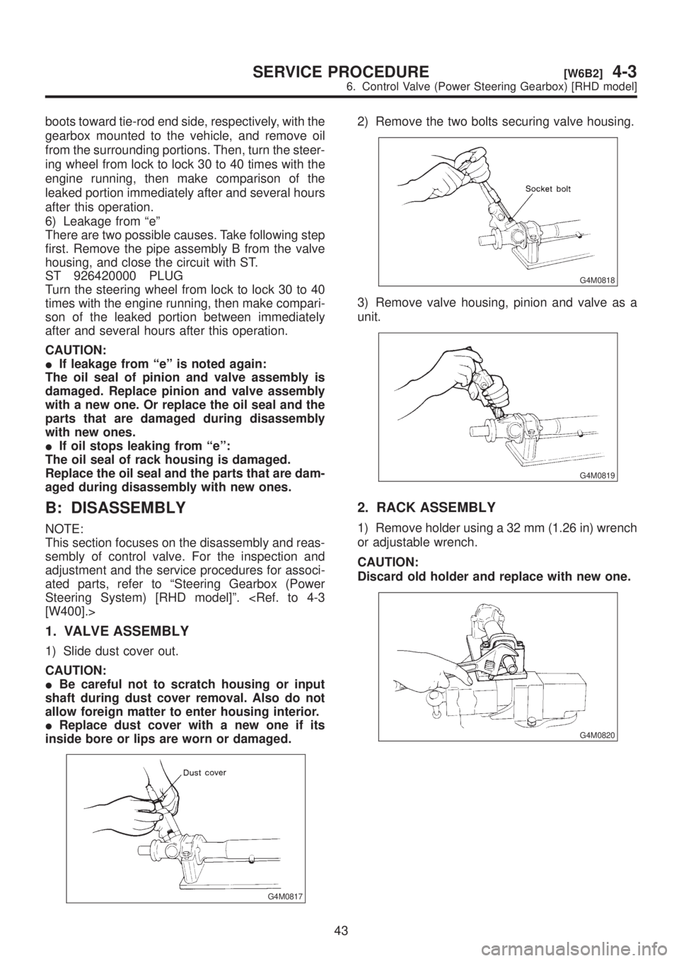
1. VALVE ASSEMBLY
1) Slide dust cover out.
CAUTION:
IBe careful not to scratch housing or input
shaft during dust cover removal. Also do not
allow foreign matter to enter housing interior.
IReplace dust cover with a new one if its
inside bore or lips are worn or damaged.
G4M0817
2) Remove the two bolts securing valve housing.
G4M0818
3) Remove valve housing, pinion and valve as a
unit.
G4M0819
2. RACK ASSEMBLY
1) Remove holder using a 32 mm (1.26 in) wrench
or adjustable wrench.
CAUTION:
Discard old holder and replace with new one.
G4M0820
43
[W6B2]4-3SERVICE PROCEDURE
6. Control Valve (Power Steering Gearbox) [RHD model]
Page 852 of 1456
8. Oil Pump (Power Steering
System)
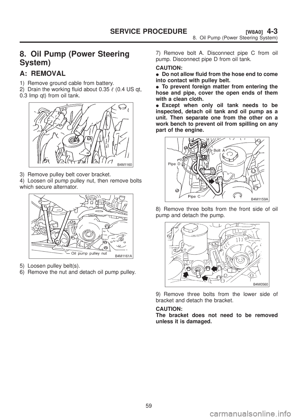
A: REMOVAL
1) Remove ground cable from battery.
2) Drain the working fluid about 0.35(0.4 US qt,
0.3 Imp qt) from oil tank.
B4M1160
3) Remove pulley belt cover bracket.
4) Loosen oil pump pulley nut, then remove bolts
which secure alternator.
B4M1161A
5) Loosen pulley belt(s).
6) Remove the nut and detach oil pump pulley.7) Remove bolt A. Disconnect pipe C from oil
pump. Disconnect pipe D from oil tank.
CAUTION:
IDo not allow fluid from the hose end to come
into contact with pulley belt.
ITo prevent foreign matter from entering the
hose and pipe, cover the open ends of them
with a clean cloth.
IExcept when only oil tank needs to be
inspected, detach oil tank and oil pump as a
unit. Then separate one from the other on a
work bench to prevent oil from spilling on any
part of the engine.
B4M1159A
8) Remove three bolts from the front side of oil
pump and detach the pump.
B4M0560
9) Remove three bolts from the lower side of
bracket and detach the bracket.
CAUTION:
The bracket does not need to be removed
unless it is damaged.
59
[W8A0]4-3SERVICE PROCEDURE
8. Oil Pump (Power Steering System)
Page 859 of 1456
improper installation. Eliminate the cause of
trouble.
(2) Check followings by referring to ªCHECKº
article.
IExcessive play in pulley shaft
IDitch deflection of pulley
IResistance to rotation of pulley
IMeasurement of generated oil pressure
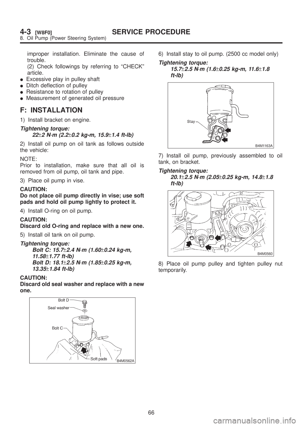
F: INSTALLATION
1) Install bracket on engine.
Tightening torque:
22
±2 N´m (2.2±0.2 kg-m, 15.9±1.4 ft-lb)
2) Install oil pump on oil tank as follows outside
the vehicle:
NOTE:
Prior to installation, make sure that all oil is
removed from oil pump, oil tank and pipe.
3) Place oil pump in vise.
CAUTION:
Do not place oil pump directly in vise; use soft
pads and hold oil pump lightly to protect it.
4) Install O-ring on oil pump.
CAUTION:
Discard old O-ring and replace with a new one.
5) Install oil tank on oil pump.
Tightening torque:
Bolt C: 15.7
±2.4 N´m (1.60±0.24 kg-m,
11.58
±1.77 ft-lb)
Bolt D: 18.1
±2.5 N´m (1.85±0.25 kg-m,
13.35
±1.84 ft-lb)
CAUTION:
Discard old seal washer and replace with a new
one.
B4M0562A
6) Install stay to oil pump. (2500 cc model only)
Tightening torque:
15.7
±2.5 N´m (1.6±0.25 kg-m, 11.6±1.8
ft-lb)
B4M1163A
7) Install oil pump, previously assembled to oil
tank, on bracket.
Tightening torque:
20.1
±2.5 N´m (2.05±0.25 kg-m, 14.8±1.8
ft-lb)
B4M0560
8) Place oil pump pulley and tighten pulley nut
temporarily.
66
4-3[W8F0]SERVICE PROCEDURE
8. Oil Pump (Power Steering System)
Page 860 of 1456
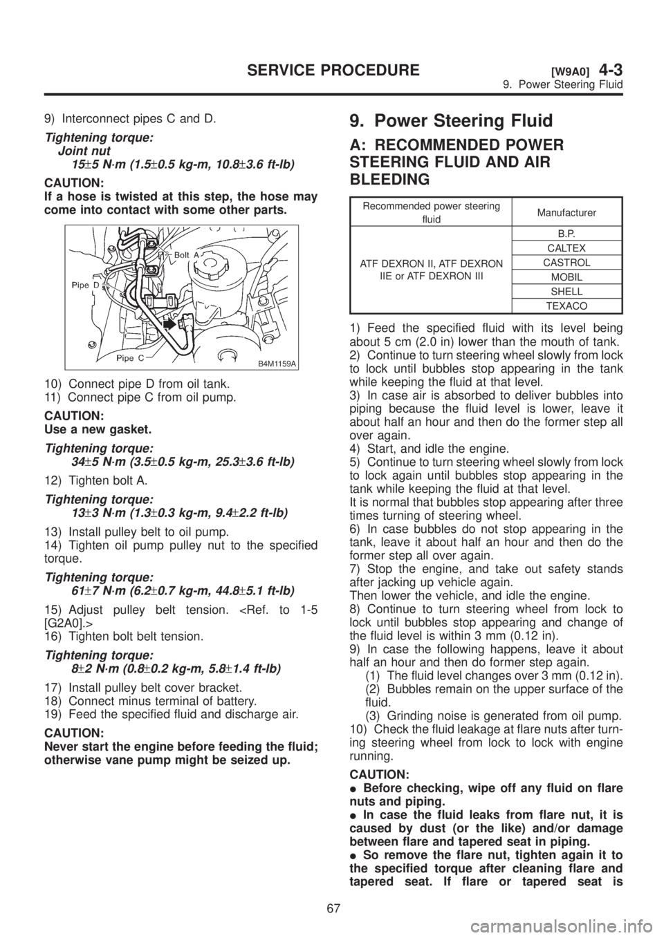
9) Interconnect pipes C and D.
Tightening torque:
Joint nut
15
±5 N´m (1.5±0.5 kg-m, 10.8±3.6 ft-lb)
CAUTION:
If a hose is twisted at this step, the hose may
come into contact with some other parts.
B4M1159A
10) Connect pipe D from oil tank.
11) Connect pipe C from oil pump.
CAUTION:
Use a new gasket.
Tightening torque:
34
±5 N´m (3.5±0.5 kg-m, 25.3±3.6 ft-lb)
12) Tighten bolt A.
Tightening torque:
13
±3 N´m (1.3±0.3 kg-m, 9.4±2.2 ft-lb)
13) Install pulley belt to oil pump.
14) Tighten oil pump pulley nut to the specified
torque.
Tightening torque:
61
±7 N´m (6.2±0.7 kg-m, 44.8±5.1 ft-lb)
15) Adjust pulley belt tension.
16) Tighten bolt belt tension.
Tightening torque:
8
±2 N´m (0.8±0.2 kg-m, 5.8±1.4 ft-lb)
17) Install pulley belt cover bracket.
18) Connect minus terminal of battery.
19) Feed the specified fluid and discharge air.
CAUTION:
Never start the engine before feeding the fluid;
otherwise vane pump might be seized up.
9. Power Steering Fluid
A: RECOMMENDED POWER
STEERING FLUID AND AIR
BLEEDING
Recommended power steering
fluidManufacturer
ATF DEXRON II, ATF DEXRON
IIE or ATF DEXRON IIIB.P.
CALTEX
CASTROL
MOBIL
SHELL
TEXACO
1) Feed the specified fluid with its level being
about 5 cm (2.0 in) lower than the mouth of tank.
2) Continue to turn steering wheel slowly from lock
to lock until bubbles stop appearing in the tank
while keeping the fluid at that level.
3) In case air is absorbed to deliver bubbles into
piping because the fluid level is lower, leave it
about half an hour and then do the former step all
over again.
4) Start, and idle the engine.
5) Continue to turn steering wheel slowly from lock
to lock again until bubbles stop appearing in the
tank while keeping the fluid at that level.
It is normal that bubbles stop appearing after three
times turning of steering wheel.
6) In case bubbles do not stop appearing in the
tank, leave it about half an hour and then do the
former step all over again.
7) Stop the engine, and take out safety stands
after jacking up vehicle again.
Then lower the vehicle, and idle the engine.
8) Continue to turn steering wheel from lock to
lock until bubbles stop appearing and change of
the fluid level is within 3 mm (0.12 in).
9) In case the following happens, leave it about
half an hour and then do former step again.
(1) The fluid level changes over 3 mm (0.12 in).
(2) Bubbles remain on the upper surface of the
fluid.
(3) Grinding noise is generated from oil pump.
10) Check the fluid leakage at flare nuts after turn-
ing steering wheel from lock to lock with engine
running.
CAUTION:
IBefore checking, wipe off any fluid on flare
nuts and piping.
IIn case the fluid leaks from flare nut, it is
caused by dust (or the like) and/or damage
between flare and tapered seat in piping.
ISo remove the flare nut, tighten again it to
the specified torque after cleaning flare and
tapered seat. If flare or tapered seat is
67
[W9A0]4-3SERVICE PROCEDURE
9. Power Steering Fluid
Page 861 of 1456
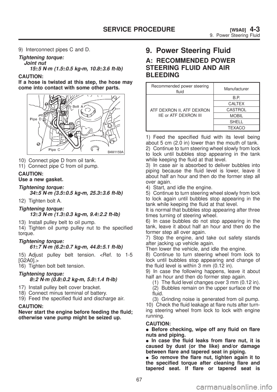
9) Interconnect pipes C and D.
Tightening torque:
Joint nut
15
±5 N´m (1.5±0.5 kg-m, 10.8±3.6 ft-lb)
CAUTION:
If a hose is twisted at this step, the hose may
come into contact with some other parts.
B4M1159A
10) Connect pipe D from oil tank.
11) Connect pipe C from oil pump.
CAUTION:
Use a new gasket.
Tightening torque:
34
±5 N´m (3.5±0.5 kg-m, 25.3±3.6 ft-lb)
12) Tighten bolt A.
Tightening torque:
13
±3 N´m (1.3±0.3 kg-m, 9.4±2.2 ft-lb)
13) Install pulley belt to oil pump.
14) Tighten oil pump pulley nut to the specified
torque.
Tightening torque:
61
±7 N´m (6.2±0.7 kg-m, 44.8±5.1 ft-lb)
15) Adjust pulley belt tension.
16) Tighten bolt belt tension.
Tightening torque:
8
±2 N´m (0.8±0.2 kg-m, 5.8±1.4 ft-lb)
17) Install pulley belt cover bracket.
18) Connect minus terminal of battery.
19) Feed the specified fluid and discharge air.
CAUTION:
Never start the engine before feeding the fluid;
otherwise vane pump might be seized up.
9. Power Steering Fluid
A: RECOMMENDED POWER
STEERING FLUID AND AIR
BLEEDING
Recommended power steering
fluidManufacturer
ATF DEXRON II, ATF DEXRON
IIE or ATF DEXRON IIIB.P.
CALTEX
CASTROL
MOBIL
SHELL
TEXACO
1) Feed the specified fluid with its level being
about 5 cm (2.0 in) lower than the mouth of tank.
2) Continue to turn steering wheel slowly from lock
to lock until bubbles stop appearing in the tank
while keeping the fluid at that level.
3) In case air is absorbed to deliver bubbles into
piping because the fluid level is lower, leave it
about half an hour and then do the former step all
over again.
4) Start, and idle the engine.
5) Continue to turn steering wheel slowly from lock
to lock again until bubbles stop appearing in the
tank while keeping the fluid at that level.
It is normal that bubbles stop appearing after three
times turning of steering wheel.
6) In case bubbles do not stop appearing in the
tank, leave it about half an hour and then do the
former step all over again.
7) Stop the engine, and take out safety stands
after jacking up vehicle again.
Then lower the vehicle, and idle the engine.
8) Continue to turn steering wheel from lock to
lock until bubbles stop appearing and change of
the fluid level is within 3 mm (0.12 in).
9) In case the following happens, leave it about
half an hour and then do former step again.
(1) The fluid level changes over 3 mm (0.12 in).
(2) Bubbles remain on the upper surface of the
fluid.
(3) Grinding noise is generated from oil pump.
10) Check the fluid leakage at flare nuts after turn-
ing steering wheel from lock to lock with engine
running.
CAUTION:
IBefore checking, wipe off any fluid on flare
nuts and piping.
IIn case the fluid leaks from flare nut, it is
caused by dust (or the like) and/or damage
between flare and tapered seat in piping.
ISo remove the flare nut, tighten again it to
the specified torque after cleaning flare and
tapered seat. If flare or tapered seat is
67
[W9A0]4-3SERVICE PROCEDURE
9. Power Steering Fluid
Page 863 of 1456
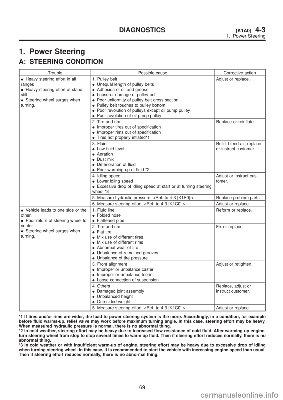
1. Power Steering
A: STEERING CONDITION
Trouble Possible cause Corrective action
IHeavy steering effort in all
ranges
IHeavy steering effort at stand
still
ISteering wheel surges when
turning.1. Pulley belt
IUnequal length of pulley belts
IAdhesion of oil and grease
ILoose or damage of pulley belt
IPoor uniformity of pulley belt cross section
IPulley belt touches to pulley bottom
IPoor revolution of pulleys except oil pump pulley
IPoor revolution of oil pump pulleyAdjust or replace.
2. Tire and rim
IImproper tires out of specification
IImproper rims out of specification
ITires not properly inflated*1Replace or reinflate.
3. Fluid
ILow fluid level
IAeration
IDust mix
IDeterioration of fluid
IPoor warming-up of fluid *2Refill, bleed air, replace
or instruct customer.
4. Idling speed
ILower idling speed
IExcessive drop of idling speed at start or at turning steering
wheel *3Adjust or instruct cus-
tomer.
5. Measure hydraulic pressure.
6. Measure steering effort.
IVehicle leads to one side or the
other.
IPoor return of steering wheel to
center
ISteering wheel surges when
turning.1. Fluid line
IFolded hose
IFlattened pipeReform or replace.
2. Tire and rim
IFlat tire
IMix use of different tires
IMix use of different rims
IAbnormal wear of tire
IUnbalance of remained grooves
IUnbalance of tire pressureFix or replace.
3. Front alignment
IImproper or unbalance caster
IImproper or unbalance toe-in
ILoose connection of suspensionAdjust or retighten.
4. Others
IDamaged joint assembly
IUnbalanced height
IOne-sided weightReplace, adjust or
instruct customer.
5. Measure steering effort.
*1 If tires and/or rims are wider, the load to power steering system is the more. Accordingly, in a condition, for example
before fluid warms-up, relief valve may work before maximum turning angle. In this case, steering effort may be heavy.
When measured hydraulic pressure is normal, there is no abnormal thing.
*2 In cold weather, steering effort may be heavy due to increased flow resistance of cold fluid. After warming up engine,
turn steering wheel from stop to stop several times to warm up fluid. Then if steering effort reduces normally, there is no
abnormal thing.
*3 In cold weather or with insufficient warm-up of engine, steering effort may be heavy due to excessive drop of idling
when turning steering wheel. In this case, it is recommended to start the vehicle with increasing engine speed than usual.
Then if steering effort reduces normally, there is no abnormal thing.
69
[K1A0]4-3DIAGNOSTICS
1. Power Steering
Page 864 of 1456
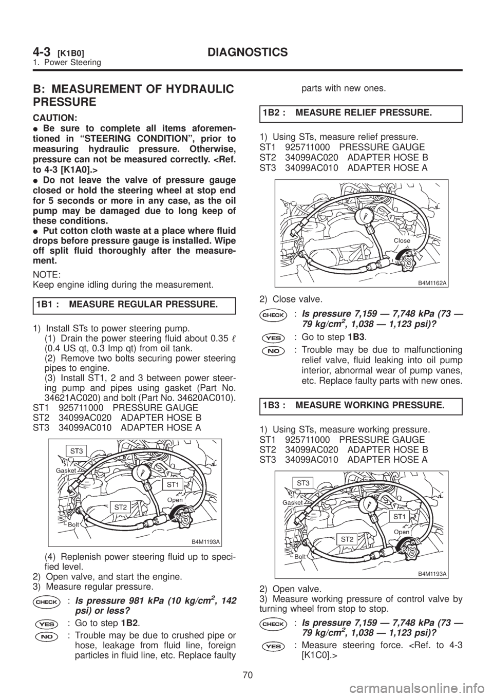
B: MEASUREMENT OF HYDRAULIC
PRESSURE
CAUTION:
IBe sure to complete all items aforemen-
tioned in ªSTEERING CONDITIONº, prior to
measuring hydraulic pressure. Otherwise,
pressure can not be measured correctly.
IDo not leave the valve of pressure gauge
closed or hold the steering wheel at stop end
for 5 seconds or more in any case, as the oil
pump may be damaged due to long keep of
these conditions.
IPut cotton cloth waste at a place where fluid
drops before pressure gauge is installed. Wipe
off split fluid thoroughly after the measure-
ment.
NOTE:
Keep engine idling during the measurement.
1B1 : MEASURE REGULAR PRESSURE.
1) Install STs to power steering pump.
(1) Drain the power steering fluid about 0.35
(0.4 US qt, 0.3 Imp qt) from oil tank.
(2) Remove two bolts securing power steering
pipes to engine.
(3) Install ST1, 2 and 3 between power steer-
ing pump and pipes using gasket (Part No.
34621AC020) and bolt (Part No. 34620AC010).
ST1 925711000 PRESSURE GAUGE
ST2 34099AC020 ADAPTER HOSE B
ST3 34099AC010 ADAPTER HOSE A
B4M1193A
(4) Replenish power steering fluid up to speci-
fied level.
2) Open valve, and start the engine.
3) Measure regular pressure.
:Is pressure 981 kPa (10 kg/cm2, 142
psi) or less?
: Go to step1B2.
: Trouble may be due to crushed pipe or
hose, leakage from fluid line, foreign
particles in fluid line, etc. Replace faultyparts with new ones.
1B2 : MEASURE RELIEF PRESSURE.
1) Using STs, measure relief pressure.
ST1 925711000 PRESSURE GAUGE
ST2 34099AC020 ADAPTER HOSE B
ST3 34099AC010 ADAPTER HOSE A
B4M1162A
2) Close valve.
:Is pressure 7,159 Ð 7,748 kPa (73 Ð
79 kg/cm2, 1,038 Ð 1,123 psi)?
: Go to step1B3.
: Trouble may be due to malfunctioning
relief valve, fluid leaking into oil pump
interior, abnormal wear of pump vanes,
etc. Replace faulty parts with new ones.
1B3 : MEASURE WORKING PRESSURE.
1) Using STs, measure working pressure.
ST1 925711000 PRESSURE GAUGE
ST2 34099AC020 ADAPTER HOSE B
ST3 34099AC010 ADAPTER HOSE A
B4M1193A
2) Open valve.
3) Measure working pressure of control valve by
turning wheel from stop to stop.
:Is pressure 7,159 Ð 7,748 kPa (73 Ð
79 kg/cm2, 1,038 Ð 1,123 psi)?
: Measure steering force.
70
4-3[K1B0]DIAGNOSTICS
1. Power Steering
Page 868 of 1456

Fluid leaking area Possible cause Corrective action
Leakage from connecting portions of
pipes and hoses, numbered with (1) thru
(9) in figureInsufficient tightening of flare nut, catch-
ing dirt or the like, damage to flare or
flare nutLoosen and retighten, if ineffective,
replace.
Poor insertion of hose, poor clamping Retighten or replace clamp.
Damaged O-ring Replace O-ring pipe or hose with new
one, if ineffective, replace gearbox also.
Leakage from hose (10) and (11) in fig-
ureCrack or damage in hose Replace with a new one.
Crack or damage in hose hardware Replace with a new one.
Leakage from surrounding of cast iron
portion of oil pump (12) and (13) in fig-
ureDamaged O-ring Replace O-ring.
Damaged gasket Replace gasket.
Leakage from oil tank, (14) and (15) in
figureCrack in oil tank, (14) Replace oil tank.
Damaged O-ring, (15) Replace O-ring.
Leakage from filler neck (16) Damaged cap packing Replace cap.
Crack in root of filler neck Replace oil tank.
High fluid level *1 Adjust fluid level.
Leakage from surrounding of power cyl-
inder of gearbox, (17) in figureDamaged oil seal Replace oil seal.
Leakage from control valve of gearbox,
(18) and (19) in figureDamaged packing or oil seal Replace problem parts.
Damage in control valve Replace control valve.
*1 Fluid level is specified at optimum position (range) for ordinary use. Accordingly, if the vehicle is used often under hard
conditions such as on very rough roads or in mountainous areas, fluid may bleed out from cap air vent hole. This is not
a problem. If a customer complains strongly and is not likely to be satisfied with the leakage, lower the fluid level to the
extent that fluid will not bleed out under the conditions described, and have the customer check the fluid level and its
quality more frequency than usual.
E: NOISE AND VIBRATION
CAUTION:
Don't keep the relief valve operated over 5 sec-
onds at any time or inner parts of the oil pump
may be damaged due to rapid increase of fluid
temperature.
NOTE:
IGrinding noise may be heard immediately after
the engine start in extremely cold condition. In this
case, if the noise goes off during warm-up there is
no abnormal function in the system. This is due to
the fluid characteristic in extremely cold condition.
IOil pump makes whine or growl noise slightly
due to its mechanism. Even if the noise can be
heard when steering wheel is turned at stand still
there is no abnormal function in the system pro-
vided that the noise eliminates when the vehicle is
running.
IWhen stopping with service brake and/or park-
ing brake applied, power steering can be operated
easily due to its light steering effort. If doing so, thedisk rotates slightly and makes creaking noise. The
noise is generated by creaking between the disk
and pads. If the noise goes off when the brake is
released, there is no abnormal function in the sys-
tem.
IThere may be a little vibration around the steer-
ing devices when turning steering wheel at
standstill, even though the component parts are
properly adjusted and have no defects.
Hydraulic systems are likely to generate this kind
of vibration as well as working noise and fluid noise
because of combined conditions, i.e., road surface
and tire surface, engine speed and turning speed
of steering wheel, fluid temperature and braking
condition.
This phenomena does not indicate there is some
abnormal function in the system.
The vibration can be known when steering wheel
is turned repeatedly at various speeds from slow to
rapid step by step with parking brake applied on
concrete road and in ªDº range for automatic trans-
mission vehicle.
Trouble Possible cause Corrective action
Hiss noise (continuous)
While engine is running.Relief valve emits operating sound when steering wheel is
completely turned in either direction. (Don't keep this condition
over 5 seconds.)Normal
Relief valve emits operating sound when steering wheel is not
turned. This means that the relief valve is faulty.Defective
Replace oil pump.
74
4-3[K1E0]DIAGNOSTICS
1. Power Steering