1999 SUBARU LEGACY engine oil
[x] Cancel search: engine oilPage 869 of 1456
![SUBARU LEGACY 1999 Service Repair Manual Trouble Possible cause Corrective action
Rattling noise (intermittent)
While engine is running.Interference with adjacent parts Check clearance.
Correct if necessary.
<Ref. to 4-3 [K1F0].>
Loosened in SUBARU LEGACY 1999 Service Repair Manual Trouble Possible cause Corrective action
Rattling noise (intermittent)
While engine is running.Interference with adjacent parts Check clearance.
Correct if necessary.
<Ref. to 4-3 [K1F0].>
Loosened in](/manual-img/17/57435/w960_57435-868.png)
Trouble Possible cause Corrective action
Rattling noise (intermittent)
While engine is running.Interference with adjacent parts Check clearance.
Correct if necessary.
Loosened installation of oil pump, oil tank, pump bracket, gear-
box or crossmemberRetighten.
Loosened installation of oil pump pulley or other pulley(s) Retighten.
Loosened linkage or play of steering or suspension
Loosened tightening of joint or steering columnRetighten or replace.
Sound generates from the inside of gearbox or oil pump. Replace the gearbox or oil
pump.
Knocking
When turning steering wheel
in both direction with small
angle repeatedly at engine
ON or OFF.Excessive backlash
Loosened lock nut for adjusting backlashAdjust and retighten.
Loosened tightening or play of tie-rod, tie-rod end Retighten or replace.
Grinding noise (continuous)
While engine is running.Vane pump aeration Inspect and retighten fluid line
connection.
Refill fluid and vent air.
Vane pump seizing Replace oil pump.
Pulley bearing seizing of oil pump Replace oil pump.
Folded hose, flat pipe Replace.
Squeal, squeak (intermittent
or continuous)
While engine is running.Maladjustment of pulley belt
Damaged or charged pulley belt
Unequal length of pulley beltsAdjust or replace.
(Replace two belts as a set.)
Run out or soilage of V-groove surface of oil pump pulley Clean or replace.
Sizzling noise (continuous)
While engine is running.Fluid aeration Fix wrong part causing aera-
tion.
Replace fluid and vent air.
Damaged pipe of gearbox Replace pipe.
Abnormal inside of hose or pipe
Flat hose or pipeRectify or replace.
Abnormal inside of oil tank Replace.
Removed oil tank cap Install cap.
Whistle (continuous)
While engine is running.Abnormal pipe of gearbox or abnormal inside of hose Replace bad parts of gearbox
or hose.
Whine or growl (continuous or
intermittent)
While engine is running with/
without steering turned.Loosened installation of oil pump, oil pump bracket Retighten.
Abnormal inside of oil pump, hose Replace oil pump, hose, if the
noise can be heard when run-
ning as well as stand still.
Torque converter growl air conditioner compression growl Remove power steering pul-
ley belt and confirm.
Creaking noise (intermittent)
While engine is running with
steering turned.Abnormal inside of gearbox Replace bad parts of gear-
box.
Abnormal bearing for steering shaft Apply grease or replace.
Generates when turning steering wheel with brake (service or
parking) applied.If the noise goes off when
brake is released, it is normal.
Vibration
While engine is running with/
without steering turned.Too low engine speed at start Adjust and instruct custom-
ers.
Vane pump aeration Fix wrong part.
Vent air.
Damaged valve in oil pump, gearbox Replace oil pump, bad parts
of gearbox.
Looseness of play of steering, suspension parts Retighten.
75
[K1E0]4-3DIAGNOSTICS
1. Power Steering
Page 870 of 1456
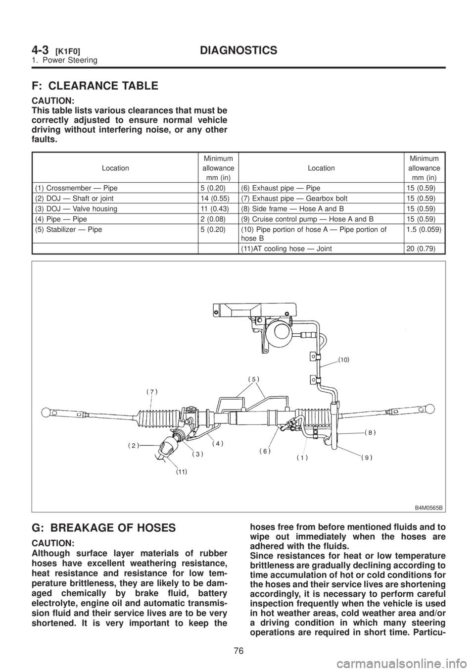
F: CLEARANCE TABLE
CAUTION:
This table lists various clearances that must be
correctly adjusted to ensure normal vehicle
driving without interfering noise, or any other
faults.
LocationMinimum
allowance
mm (in)LocationMinimum
allowance
mm (in)
(1) Crossmember Ð Pipe 5 (0.20) (6) Exhaust pipe Ð Pipe 15 (0.59)
(2) DOJ Ð Shaft or joint 14 (0.55) (7) Exhaust pipe Ð Gearbox bolt 15 (0.59)
(3) DOJ Ð Valve housing 11 (0.43) (8) Side frame Ð Hose A and B 15 (0.59)
(4) Pipe Ð Pipe 2 (0.08) (9) Cruise control pump Ð Hose A and B 15 (0.59)
(5) Stabilizer Ð Pipe 5 (0.20) (10) Pipe portion of hose A Ð Pipe portion of
hose B1.5 (0.059)
(11)AT cooling hose Ð Joint 20 (0.79)
B4M0565B
G: BREAKAGE OF HOSES
CAUTION:
Although surface layer materials of rubber
hoses have excellent weathering resistance,
heat resistance and resistance for low tem-
perature brittleness, they are likely to be dam-
aged chemically by brake fluid, battery
electrolyte, engine oil and automatic transmis-
sion fluid and their service lives are to be very
shortened. It is very important to keep thehoses free from before mentioned fluids and to
wipe out immediately when the hoses are
adhered with the fluids.
Since resistances for heat or low temperature
brittleness are gradually declining according to
time accumulation of hot or cold conditions for
the hoses and their service lives are shortening
accordingly, it is necessary to perform careful
inspection frequently when the vehicle is used
in hot weather areas, cold weather area and/or
a driving condition in which many steering
operations are required in short time. Particu-
76
4-3[K1F0]DIAGNOSTICS
1. Power Steering
Page 871 of 1456
larly continuous work of relief valve over 5 sec-
onds causes to reduce service lives of the
hoses, the oil pump, the fluid, etc. due to over
heat.So, avoid to keep this kind of condition when
servicing as well as driving.
Trouble Possible cause Corrective action
Pressure hose burst Excessive holding time of relief status Instruct customers.
Malfunction of relief valve Replace oil pump.
Poor cold characteristic of fluid Replace fluid.
Forced out return hose Poor connection Correct.
Poor holding of clip Retighten.
Poor cold characteristic of fluid Replace fluid.
Fluid bleeding out of hose
slightlyWrong layout, tensioned Replace hose.
Excessive play of engine due to deterioration of engine
mounting rubberReplace defective parts.
Improper stop position of pitching stopper Replace defective parts.
Crack on hose Excessive holding time of relief status Replace.
Instruct customer.
Excessive tightening torque for return hose clip Replace.
Power steering fluid, brake fluid, engine oil, electrolyte
adhere on the hose surfaceReplace.
Pay attention on service work.
Too many times use in extremely cold weather Replace.
Instruct customers.
77
[K1G0]4-3DIAGNOSTICS
1. Power Steering
Page 995 of 1456
8. Leak Testing
A: INSPECTION
The following points should be kept in mind when
conducting a refrigerant leak test.
1) The A/C system to be tested must have an
adequate refrigerant charge to begin with.
2) The area where the leak test is conducted must
be free of wind and drafts, with still air being the
ideal condition.
3) The atmosphere where the leak test is con-
ducted must be free of refrigerant contamination.
4) Operate the A/C system for approx. 10 minutes,
then turn the engine off an begin the leak test.
5) Refrigerant gas is heavier than air, therefore
always hold the probe below the connection being
tested.
6) When checking for a leak along a length of
hose or tube, the leak detector probe must be
moved slowly, approx. 25 mm (1 in) per second
making sure probe does not come in contact with
the component being tested.
7) When checking for a leak at a certain point, the
leak detector probe must be held at that point for
at least 5 seconds.
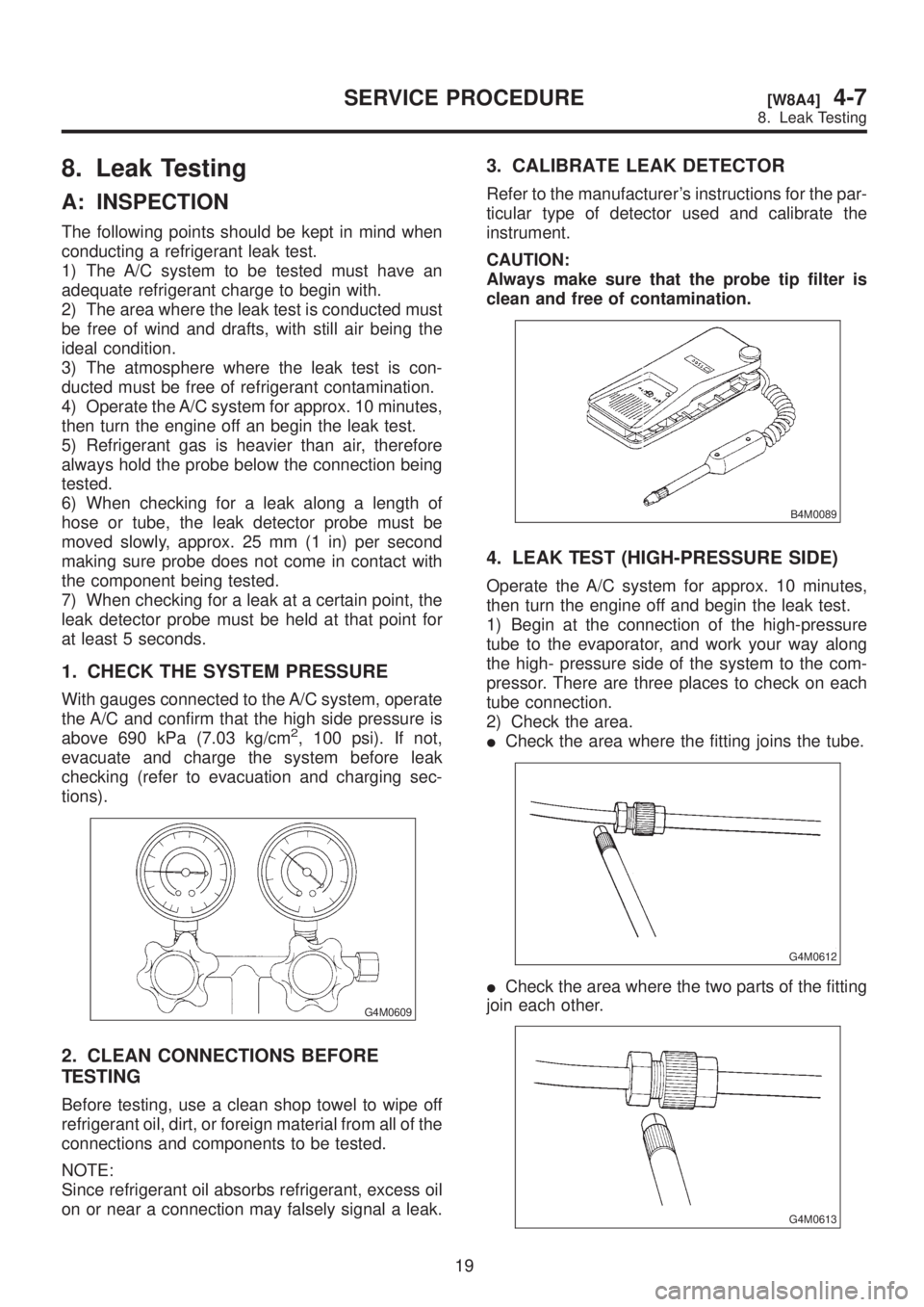
1. CHECK THE SYSTEM PRESSURE
With gauges connected to the A/C system, operate
the A/C and confirm that the high side pressure is
above 690 kPa (7.03 kg/cm
2, 100 psi). If not,
evacuate and charge the system before leak
checking (refer to evacuation and charging sec-
tions).
G4M0609
2. CLEAN CONNECTIONS BEFORE
TESTING
Before testing, use a clean shop towel to wipe off
refrigerant oil, dirt, or foreign material from all of the
connections and components to be tested.
NOTE:
Since refrigerant oil absorbs refrigerant, excess oil
on or near a connection may falsely signal a leak.
3. CALIBRATE LEAK DETECTOR
Refer to the manufacturer's instructions for the par-
ticular type of detector used and calibrate the
instrument.
CAUTION:
Always make sure that the probe tip filter is
clean and free of contamination.
B4M0089
4. LEAK TEST (HIGH-PRESSURE SIDE)
Operate the A/C system for approx. 10 minutes,
then turn the engine off and begin the leak test.
1) Begin at the connection of the high-pressure
tube to the evaporator, and work your way along
the high- pressure side of the system to the com-
pressor. There are three places to check on each
tube connection.
2) Check the area.
ICheck the area where the fitting joins the tube.
G4M0612
ICheck the area where the two parts of the fitting
join each other.
G4M0613
19
[W8A4]4-7SERVICE PROCEDURE
8. Leak Testing
Page 997 of 1456
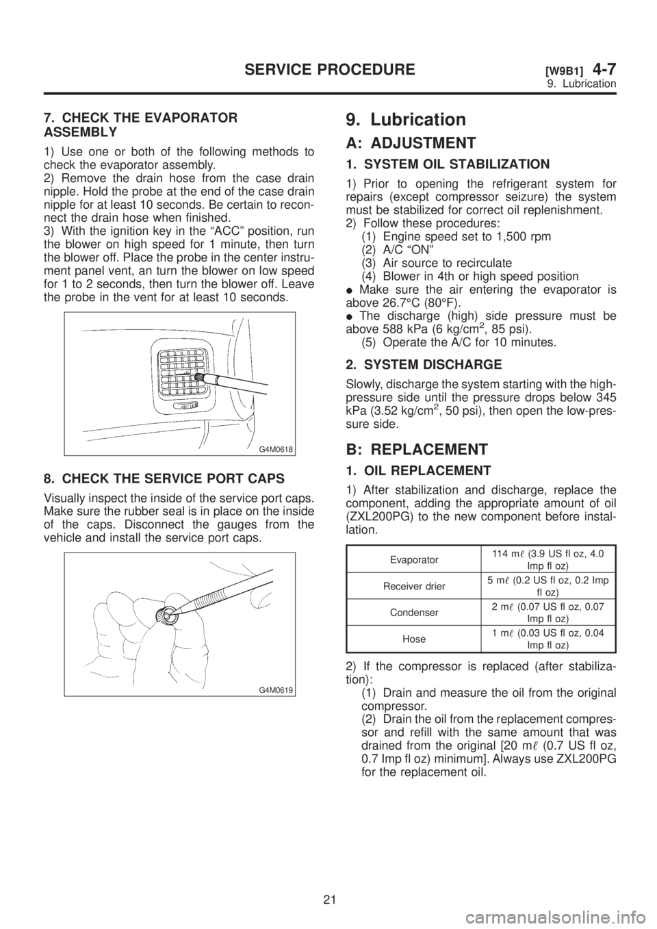
7. CHECK THE EVAPORATOR
ASSEMBLY
1) Use one or both of the following methods to
check the evaporator assembly.
2) Remove the drain hose from the case drain
nipple. Hold the probe at the end of the case drain
nipple for at least 10 seconds. Be certain to recon-
nect the drain hose when finished.
3) With the ignition key in the ªACCº position, run
the blower on high speed for 1 minute, then turn
the blower off. Place the probe in the center instru-
ment panel vent, an turn the blower on low speed
for 1 to 2 seconds, then turn the blower off. Leave
the probe in the vent for at least 10 seconds.
G4M0618
8. CHECK THE SERVICE PORT CAPS
Visually inspect the inside of the service port caps.
Make sure the rubber seal is in place on the inside
of the caps. Disconnect the gauges from the
vehicle and install the service port caps.
G4M0619
9. Lubrication
A: ADJUSTMENT
1. SYSTEM OIL STABILIZATION
1) Prior to opening the refrigerant system for
repairs (except compressor seizure) the system
must be stabilized for correct oil replenishment.
2) Follow these procedures:
(1) Engine speed set to 1,500 rpm
(2) A/C ªONº
(3) Air source to recirculate
(4) Blower in 4th or high speed position
IMake sure the air entering the evaporator is
above 26.7ÉC (80ÉF).
IThe discharge (high) side pressure must be
above 588 kPa (6 kg/cm
2, 85 psi).
(5) Operate the A/C for 10 minutes.
2. SYSTEM DISCHARGE
Slowly, discharge the system starting with the high-
pressure side until the pressure drops below 345
kPa (3.52 kg/cm
2, 50 psi), then open the low-pres-
sure side.
B: REPLACEMENT
1. OIL REPLACEMENT
1) After stabilization and discharge, replace the
component, adding the appropriate amount of oil
(ZXL200PG) to the new component before instal-
lation.
Evaporator11 4 m(3.9 US fl oz, 4.0
Imp fl oz)
Receiver drier5m(0.2 US fl oz, 0.2 Imp
fl oz)
Condenser2m(0.07 US fl oz, 0.07
Imp fl oz)
Hose1m(0.03 US fl oz, 0.04
Imp fl oz)
2) If the compressor is replaced (after stabiliza-
tion):
(1) Drain and measure the oil from the original
compressor.
(2) Drain the oil from the replacement compres-
sor and refill with the same amount that was
drained from the original [20 m(0.7 US fl oz,
0.7 Imp fl oz) minimum]. Always use ZXL200PG
for the replacement oil.
21
[W9B1]4-7SERVICE PROCEDURE
9. Lubrication
Page 998 of 1456
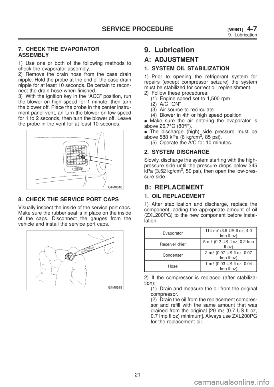
7. CHECK THE EVAPORATOR
ASSEMBLY
1) Use one or both of the following methods to
check the evaporator assembly.
2) Remove the drain hose from the case drain
nipple. Hold the probe at the end of the case drain
nipple for at least 10 seconds. Be certain to recon-
nect the drain hose when finished.
3) With the ignition key in the ªACCº position, run
the blower on high speed for 1 minute, then turn
the blower off. Place the probe in the center instru-
ment panel vent, an turn the blower on low speed
for 1 to 2 seconds, then turn the blower off. Leave
the probe in the vent for at least 10 seconds.
G4M0618
8. CHECK THE SERVICE PORT CAPS
Visually inspect the inside of the service port caps.
Make sure the rubber seal is in place on the inside
of the caps. Disconnect the gauges from the
vehicle and install the service port caps.
G4M0619
9. Lubrication
A: ADJUSTMENT
1. SYSTEM OIL STABILIZATION
1) Prior to opening the refrigerant system for
repairs (except compressor seizure) the system
must be stabilized for correct oil replenishment.
2) Follow these procedures:
(1) Engine speed set to 1,500 rpm
(2) A/C ªONº
(3) Air source to recirculate
(4) Blower in 4th or high speed position
IMake sure the air entering the evaporator is
above 26.7ÉC (80ÉF).
IThe discharge (high) side pressure must be
above 588 kPa (6 kg/cm
2, 85 psi).
(5) Operate the A/C for 10 minutes.
2. SYSTEM DISCHARGE
Slowly, discharge the system starting with the high-
pressure side until the pressure drops below 345
kPa (3.52 kg/cm
2, 50 psi), then open the low-pres-
sure side.
B: REPLACEMENT
1. OIL REPLACEMENT
1) After stabilization and discharge, replace the
component, adding the appropriate amount of oil
(ZXL200PG) to the new component before instal-
lation.
Evaporator11 4 m(3.9 US fl oz, 4.0
Imp fl oz)
Receiver drier5m(0.2 US fl oz, 0.2 Imp
fl oz)
Condenser2m(0.07 US fl oz, 0.07
Imp fl oz)
Hose1m(0.03 US fl oz, 0.04
Imp fl oz)
2) If the compressor is replaced (after stabiliza-
tion):
(1) Drain and measure the oil from the original
compressor.
(2) Drain the oil from the replacement compres-
sor and refill with the same amount that was
drained from the original [20 m(0.7 US fl oz,
0.7 Imp fl oz) minimum]. Always use ZXL200PG
for the replacement oil.
21
[W9B1]4-7SERVICE PROCEDURE
9. Lubrication
Page 1017 of 1456
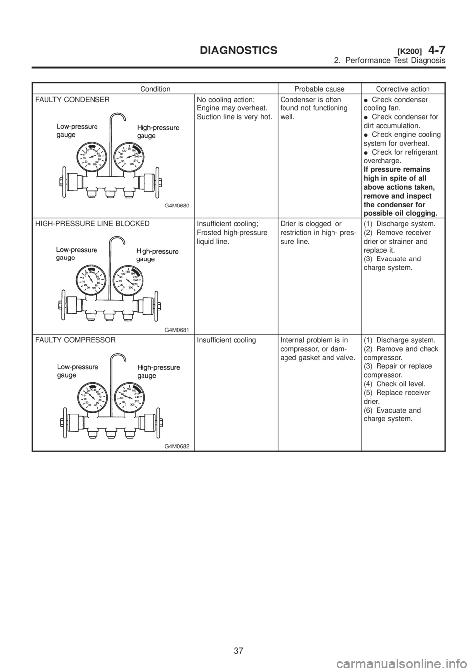
Condition Probable cause Corrective action
FAULTY CONDENSER
G4M0680
No cooling action;
Engine may overheat.
Suction line is very hot.Condenser is often
found not functioning
well.ICheck condenser
cooling fan.
ICheck condenser for
dirt accumulation.
ICheck engine cooling
system for overheat.
ICheck for refrigerant
overcharge.
If pressure remains
high in spite of all
above actions taken,
remove and inspect
the condenser for
possible oil clogging.
HIGH-PRESSURE LINE BLOCKED
G4M0681
Insufficient cooling;
Frosted high-pressure
liquid line.Drier is clogged, or
restriction in high- pres-
sure line.(1) Discharge system.
(2) Remove receiver
drier or strainer and
replace it.
(3) Evacuate and
charge system.
FAULTY COMPRESSOR
G4M0682
Insufficient cooling Internal problem is in
compressor, or dam-
aged gasket and valve.(1) Discharge system.
(2) Remove and check
compressor.
(3) Repair or replace
compressor.
(4) Check oil level.
(5) Replace receiver
drier.
(6) Evacuate and
charge system.
37
[K200]4-7DIAGNOSTICS
2. Performance Test Diagnosis
Page 1183 of 1456
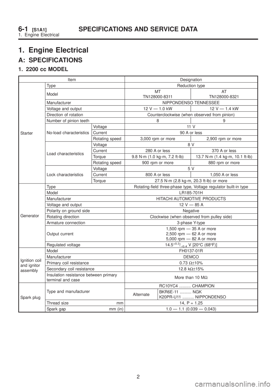
1. Engine Electrical
A: SPECIFICATIONS
1. 2200 cc MODEL
Item Designation
StarterType Reduction type
ModelMT
TN128000-8311AT
TN128000-8321
Manufacturer NIPPONDENSO TENNESSEE
Voltage and output 12 V Ð 1.0 kW 12 V Ð 1.4 kW
Direction of rotation Counterclockwise (when observed from pinion)
Number of pinion teeth 8 9
No-load characteristicsVoltage 11 V
Current 90 A or less
Rotating speed 3,000 rpm or more 2,900 rpm or more
Load characteristicsVoltage 8 V
Current 280 A or less 370 A or less
Torque 9.8 N´m (1.0 kg-m, 7.2 ft-lb) 13.7 N´m (1.4 kg-m, 10.1 ft-lb)
Rotating speed 900 rpm or more 880 rpm or more
Lock characteristicsVoltage 5 V
Current 800 A or less 1,050 A or less
Torque 27.5 N´m (2.8 kg-m, 20.3 ft-lb) or more
GeneratorType Rotating-field three-phase type, Voltage regulator built-in type
Model LR185-701H
Manufacturer HITACHI AUTOMOTIVE PRODUCTS
Voltage and output 12VÐ85A
Polarity on ground side Negative
Rotating direction Clockwise (when observed from pulley side)
Armature connection 3-phase Y-type
Output current1,500 rpm Ð 35 A or more
2,500 rpm Ð 62 A or more
5,000 rpm Ð 82 A or more
Regulated voltage 14.5
+0.3/þ0.4V [20ÉC (68ÉF)]
Ignition coil
and ignitor
assemblyModel FH0137-01R
Manufacturer DEMCO
Primary coil resistance 0.73W±10%
Secondary coil resistance 12.8 kW±15%
Insulation resistance between primary
terminal and caseMore than 10 MW
Spark plugType and manufacturerRC10YC4 .......... CHAMPION
AlternateBKR6E-11 .......... NGK
K20PR-U11 .......... NIPPONDENSO
Thread size mm 14, P = 1.25
Spark gap mm (in) 1.0 Ð 1.1 (0.039 Ð 0.043)
2
6-1[S1A1]SPECIFICATIONS AND SERVICE DATA
1. Engine Electrical