Page 42 of 1456

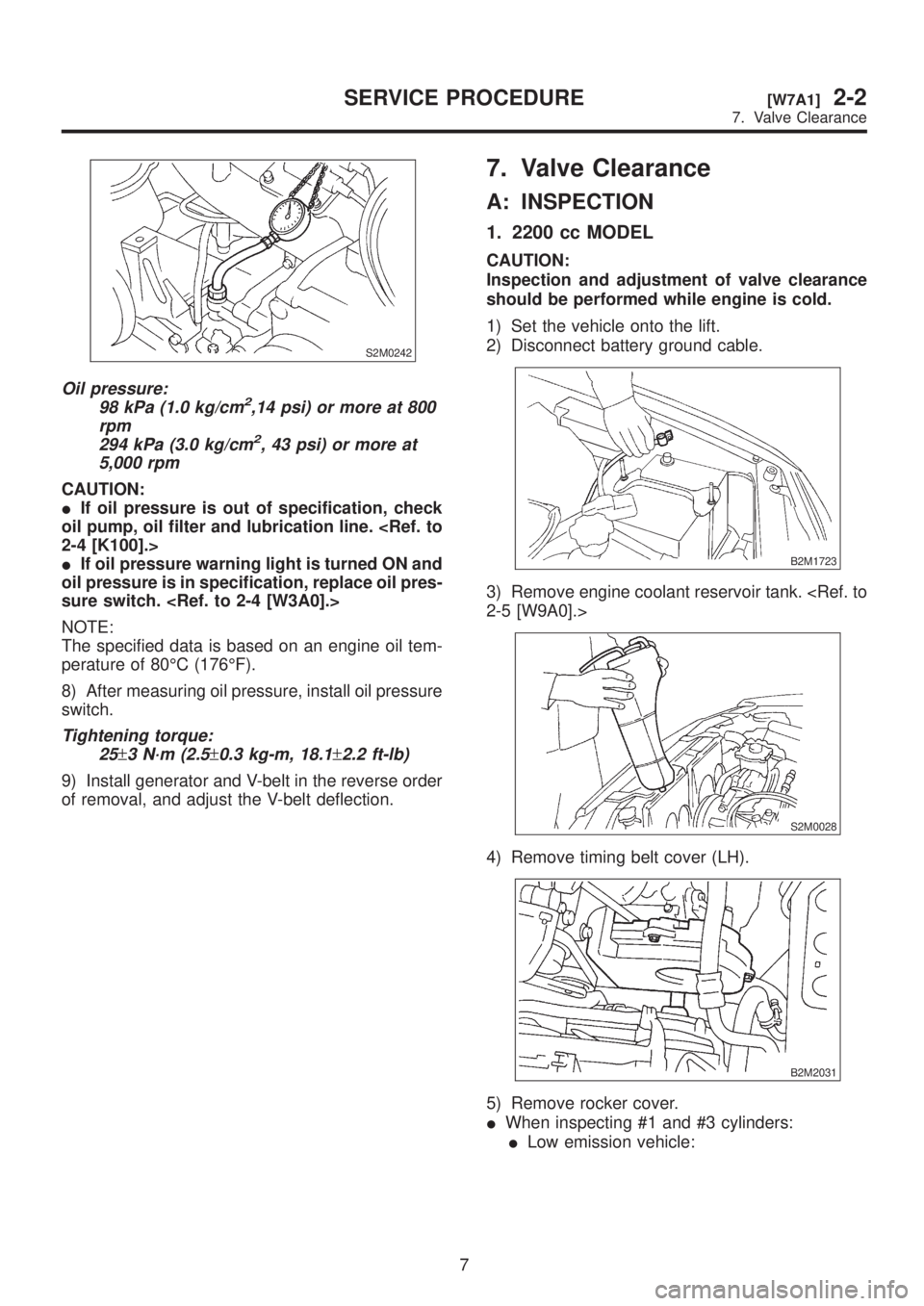
S2M0242
Oil pressure:
98 kPa (1.0 kg/cm2,14 psi) or more at 800
rpm
294 kPa (3.0 kg/cm
2, 43 psi) or more at
5,000 rpm
CAUTION:
IIf oil pressure is out of specification, check
oil pump, oil filter and lubrication line.
2-4 [K100].>
IIf oil pressure warning light is turned ON and
oil pressure is in specification, replace oil pres-
sure switch.
NOTE:
The specified data is based on an engine oil tem-
perature of 80ÉC (176ÉF).
8) After measuring oil pressure, install oil pressure
switch.
Tightening torque:
25
±3 N´m (2.5±0.3 kg-m, 18.1±2.2 ft-lb)
9) Install generator and V-belt in the reverse order
of removal, and adjust the V-belt deflection.
7. Valve Clearance
A: INSPECTION
1. 2200 cc MODEL
CAUTION:
Inspection and adjustment of valve clearance
should be performed while engine is cold.
1) Set the vehicle onto the lift.
2) Disconnect battery ground cable.
B2M1723
3) Remove engine coolant reservoir tank.
2-5 [W9A0].>
S2M0028
4) Remove timing belt cover (LH).
B2M2031
5) Remove rocker cover.
IWhen inspecting #1 and #3 cylinders:
ILow emission vehicle:
7
[W7A1]2-2SERVICE PROCEDURE
7. Valve Clearance
Page 43 of 1456

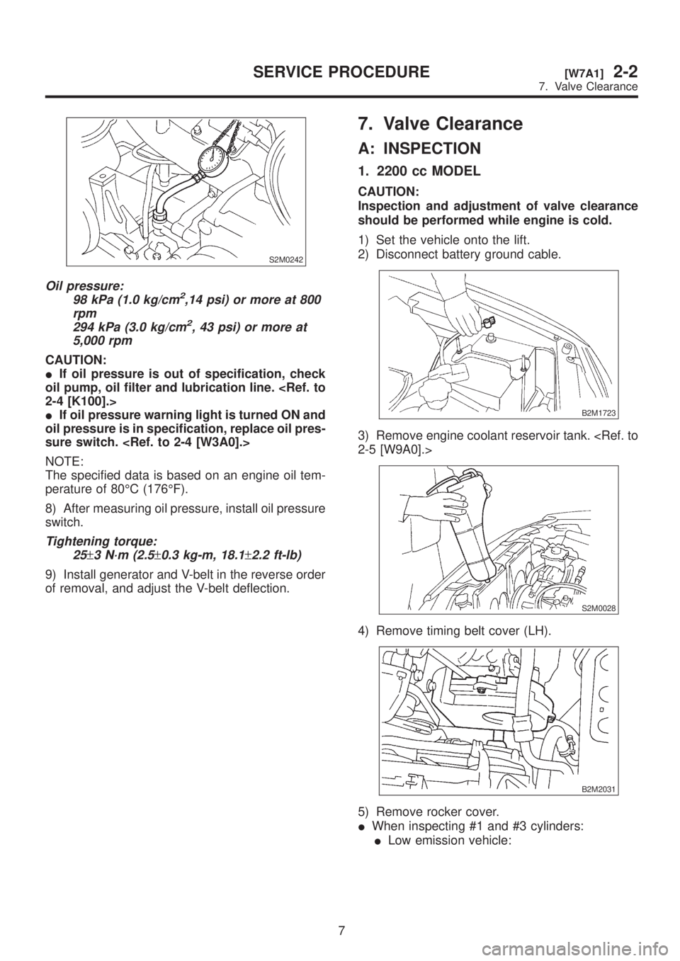
S2M0242
Oil pressure:
98 kPa (1.0 kg/cm2,14 psi) or more at 800
rpm
294 kPa (3.0 kg/cm
2, 43 psi) or more at
5,000 rpm
CAUTION:
IIf oil pressure is out of specification, check
oil pump, oil filter and lubrication line.
2-4 [K100].>
IIf oil pressure warning light is turned ON and
oil pressure is in specification, replace oil pres-
sure switch.
NOTE:
The specified data is based on an engine oil tem-
perature of 80ÉC (176ÉF).
8) After measuring oil pressure, install oil pressure
switch.
Tightening torque:
25
±3 N´m (2.5±0.3 kg-m, 18.1±2.2 ft-lb)
9) Install generator and V-belt in the reverse order
of removal, and adjust the V-belt deflection.
7. Valve Clearance
A: INSPECTION
1. 2200 cc MODEL
CAUTION:
Inspection and adjustment of valve clearance
should be performed while engine is cold.
1) Set the vehicle onto the lift.
2) Disconnect battery ground cable.
B2M1723
3) Remove engine coolant reservoir tank.
2-5 [W9A0].>
S2M0028
4) Remove timing belt cover (LH).
B2M2031
5) Remove rocker cover.
IWhen inspecting #1 and #3 cylinders:
ILow emission vehicle:
7
[W7A1]2-2SERVICE PROCEDURE
7. Valve Clearance
Page 44 of 1456
(1) Remove air intake duct A and B as a unit.
B2M2012
(2) Remove resonator chamber.
B2M2013
(3) Disconnect spark plug cords from spark
plugs (#1 and #3 cylinders).
B2M2014
(4) Disconnect blow-by hose from rocker
cover (RH).
B2M2015
(5) Lift-up the vehicle.
(6) Remove under cover (RH).
(7) Place suitable container under the
vehicle.(8) Lower the vehicle.
(9) Remove the timing belt cover (RH) bolt.
B2M2016
(10) Remove rocker cover bolts, then
remove rocker cover (RH).
B2M2017
IExcept low emission vehicle:
(1) Disconnect connector from mass air flow
sensor.
B2M2018
(2) Loosen clamp which connects air intake
duct and air intake chamber.
B2M2019
8
2-2[W7A1]SERVICE PROCEDURE
7. Valve Clearance
Page 45 of 1456
(3) Remove clips of air cleaner upper cover.
(4) Remove air intake duct and air cleaner
upper cover as a unit.
B2M2020
(5) Remove air cleaner element.
(6) Remive air cleaner lower case.
S2M0179
(7) Disconnect spark plug cords from spark
plugs (#1 and #3 cylinders).
B2M2014
(8) Disconnect blow-by hose from rocker
cover (RH).
B2M2015
(9) Lift-up the vehicle.(10) Remove under cover (RH).
(11) Place suitable container under the
vehicle.
(12) Lower the vehicle.
(13) Remove the timing belt cover (RH) bolt.
B2M2016
(14) Remove rocker cover bolts, then
remove rocker cover (RH).
B2M2017
IWhen inspecting #2 and #4 cylinders:
(1) Disconnect battery cables, and then
remove battery and battery carrier.
(2) Disconnect front window washer motor
connector.
(3) Disconnect rear gate glass washer motor
connector. (Wagon only)
S2M0546
9
[W7A1]2-2SERVICE PROCEDURE
7. Valve Clearance
Page 47 of 1456

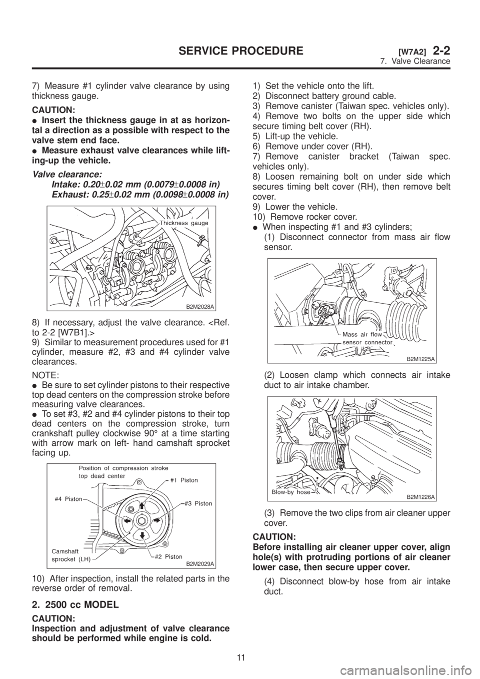
7) Measure #1 cylinder valve clearance by using
thickness gauge.
CAUTION:
IInsert the thickness gauge in at as horizon-
tal a direction as a possible with respect to the
valve stem end face.
IMeasure exhaust valve clearances while lift-
ing-up the vehicle.
Valve clearance:
Intake: 0.20
±0.02 mm (0.0079±0.0008 in)
Exhaust: 0.25
±0.02 mm (0.0098±0.0008 in)
B2M2028A
8) If necessary, adjust the valve clearance.
to 2-2 [W7B1].>
9) Similar to measurement procedures used for #1
cylinder, measure #2, #3 and #4 cylinder valve
clearances.
NOTE:
IBe sure to set cylinder pistons to their respective
top dead centers on the compression stroke before
measuring valve clearances.
ITo set #3, #2 and #4 cylinder pistons to their top
dead centers on the compression stroke, turn
crankshaft pulley clockwise 90É at a time starting
with arrow mark on left- hand camshaft sprocket
facing up.
B2M2029A
10) After inspection, install the related parts in the
reverse order of removal.
2. 2500 cc MODEL
CAUTION:
Inspection and adjustment of valve clearance
should be performed while engine is cold.1) Set the vehicle onto the lift.
2) Disconnect battery ground cable.
3) Remove canister (Taiwan spec. vehicles only).
4) Remove two bolts on the upper side which
secure timing belt cover (RH).
5) Lift-up the vehicle.
6) Remove under cover (RH).
7) Remove canister bracket (Taiwan spec.
vehicles only).
8) Loosen remaining bolt on under side which
secures timing belt cover (RH), then remove belt
cover.
9) Lower the vehicle.
10) Remove rocker cover.
IWhen inspecting #1 and #3 cylinders;
(1) Disconnect connector from mass air flow
sensor.
B2M1225A
(2) Loosen clamp which connects air intake
duct to air intake chamber.
B2M1226A
(3) Remove the two clips from air cleaner upper
cover.
CAUTION:
Before installing air cleaner upper cover, align
hole(s) with protruding portions of air cleaner
lower case, then secure upper cover.
(4) Disconnect blow-by hose from air intake
duct.
11
[W7A2]2-2SERVICE PROCEDURE
7. Valve Clearance
Page 55 of 1456

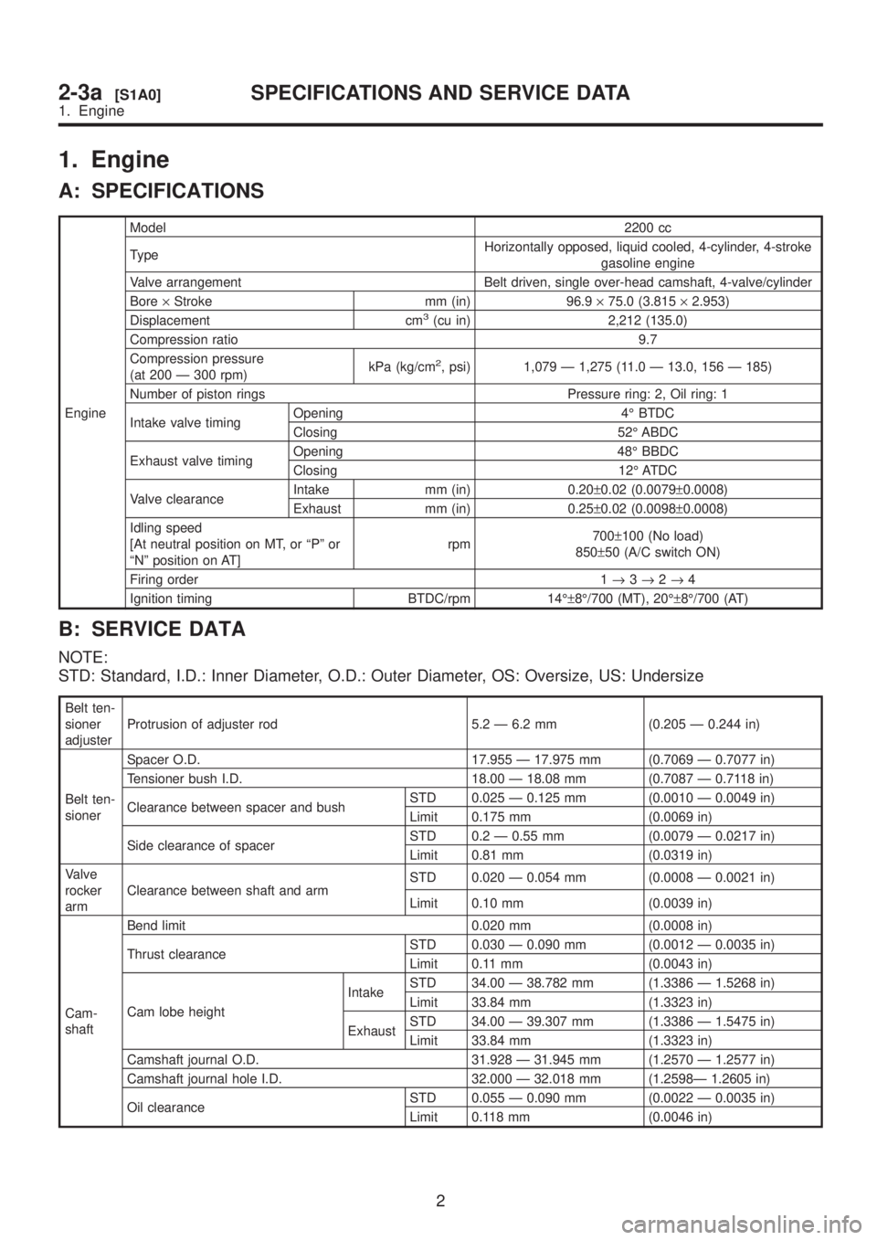
1. Engine
A: SPECIFICATIONS
EngineModel2200 cc
TypeHorizontally opposed, liquid cooled, 4-cylinder, 4-stroke
gasoline engine
Valve arrangement Belt driven, single over-head camshaft, 4-valve/cylinder
Bore´Stroke mm (in) 96.9´75.0 (3.815´2.953)
Displacement cm
3(cu in) 2,212 (135.0)
Compression ratio 9.7
Compression pressure
(at 200 Ð 300 rpm)kPa (kg/cm
2, psi) 1,079 Ð 1,275 (11.0 Ð 13.0, 156 Ð 185)
Number of piston rings Pressure ring: 2, Oil ring: 1
Intake valve timingOpening 4É BTDC
Closing 52É ABDC
Exhaust valve timingOpening 48É BBDC
Closing 12É ATDC
Valve clearanceIntake mm (in) 0.20±0.02 (0.0079±0.0008)
Exhaust mm (in) 0.25±0.02 (0.0098±0.0008)
Idling speed
[At neutral position on MT, or ªPº or
ªNº position on AT]rpm700±100 (No load)
850±50 (A/C switch ON)
Firing order 1®3®2®4
Ignition timing BTDC/rpm 14ɱ8É/700 (MT), 20ɱ8É/700 (AT)
B: SERVICE DATA
NOTE:
STD: Standard, I.D.: Inner Diameter, O.D.: Outer Diameter, OS: Oversize, US: Undersize
Belt ten-
sioner
adjusterProtrusion of adjuster rod 5.2 Ð 6.2 mm (0.205 Ð 0.244 in)
Belt ten-
sionerSpacer O.D. 17.955 Ð 17.975 mm (0.7069 Ð 0.7077 in)
Tensioner bush I.D. 18.00 Ð 18.08 mm (0.7087 Ð 0.7118 in)
Clearance between spacer and bushSTD 0.025 Ð 0.125 mm (0.0010 Ð 0.0049 in)
Limit 0.175 mm (0.0069 in)
Side clearance of spacerSTD 0.2 Ð 0.55 mm (0.0079 Ð 0.0217 in)
Limit 0.81 mm (0.0319 in)
Valve
rocker
armClearance between shaft and armSTD 0.020 Ð 0.054 mm (0.0008 Ð 0.0021 in)
Limit 0.10 mm (0.0039 in)
Cam-
shaftBend limit 0.020 mm (0.0008 in)
Thrust clearanceSTD 0.030 Ð 0.090 mm (0.0012 Ð 0.0035 in)
Limit 0.11 mm (0.0043 in)
Cam lobe heightIntakeSTD 34.00 Ð 38.782 mm (1.3386 Ð 1.5268 in)
Limit 33.84 mm (1.3323 in)
ExhaustSTD 34.00 Ð 39.307 mm (1.3386 Ð 1.5475 in)
Limit 33.84 mm (1.3323 in)
Camshaft journal O.D. 31.928 Ð 31.945 mm (1.2570 Ð 1.2577 in)
Camshaft journal hole I.D. 32.000 Ð 32.018 mm (1.2598Ð 1.2605 in)
Oil clearanceSTD 0.055 Ð 0.090 mm (0.0022 Ð 0.0035 in)
Limit 0.118 mm (0.0046 in)
2
2-3a[S1A0]SPECIFICATIONS AND SERVICE DATA
1. Engine
Page 59 of 1456
1. Timing Belt
B2M1953A
(1) Belt cover No. 2 (RH)
(2) Timing belt guide (MT vehicles
only)
(3) Crankshaft sprocket (Except
California spec. vehicles)
(4) Crankshaft sprocket (California
spec. vehicles)
(5) Belt cover No. 2 (LH)
(6) Camshaft sprocket No. 1
(7) Belt idler (No. 1)(8) Tensioner bracket
(9) Belt idler (No. 2)
(10) Automatic belt tension adjuster
ASSY
(11) Belt idler No. 2
(12) Camshaft sprocket No. 2
(13) Timing belt
(14) Front belt cover
(15) Belt cover (LH)
(16) Crankshaft pulleyTightening torque: N´m (kg-m, ft-lb)
T1:
5±1 (0.5±0.1, 3.6±0.7)
T2:9.8±1.0 (1.0±0.1, 7.2±0.7)
T3:25±3 (2.5±0.3, 18.1±2.2)
T4:39±4 (4.0±0.4, 28.9±2.9)
T5:78±5 (8.0±0.5, 57.9±3.6)
T6:127+10/þ5(13.0+1.0/þ0.5,
94+7.2/þ3.6)
6
2-3a[C100]COMPONENT PARTS
1. Timing Belt
Page 65 of 1456
1. General Precautions
A: GENERAL PRECAUTIONS
1) Before disassembling engine, place it on ST3.
ST1 498457000 ENGINE STAND ADAPTER
RH
ST2 498457100 ENGINE STAND ADAPTER
LH
ST3 499817000 ENGINE STAND
B2M2582A
2) All parts should be thoroughly cleaned, paying
special attention to the engine oil passages, pis-
tons and bearings.
3) Rotating parts and sliding parts such as piston,
bearing and gear should be coated with oil prior to
assembly.
4) Be careful not to let oil, grease or coolant con-
tact the timing belt, clutch disc and flywheel.
5) All removed parts, if to be reused, should be
reinstalled in the original positions and directions.
6) All removed parts, if to be reused, should be
reinstalled in the original positions and directions.
7) Bolts, nuts and washers should be replaced
with new ones as required.
8) Even if necessary inspections have been made
in advance, proceed with assembly work while
making rechecks.
12
2-3a[W1A0]SERVICE PROCEDURE
1. General Precautions