Page 373 of 1456
13) Loosen clamp, and disconnect evaporation
hose from canister.
B2M2381A
14) Loosen clamp, disconnect hose from joint
pipe.
B2M2382A
15) Disconnect connector from pressure control
solenoid valve.
B2M1742
16) Disconnect connector from drain valve.
B2M1743
17) Disconnect hoses from roll over valve.
S2M0167
18) Remove bolts which hold parking brake cable
holding bracket.
S2M0191
19) Remove rear differential assembly.
(1) Remove rear axle shafts from rear differen-
tial assembly.
(2) Remove rear differential front cover.
(3) Remove propeller shaft.
(4) Remove lower differential bracket.
(5) Set transmission jack under rear differential.
(6) Remove bolts which install rear differential
onto rear crossmember.
G3M0059
11
[W2A0]2-8SERVICE PROCEDURE
2. Fuel Tank
Page 456 of 1456
(8) Remove rear exhaust pipe.
CAUTION:
When removing exhaust pipes, be careful each
exhaust pipe does not drop out.
S2M0158
(9) Remove heat shield cover of rear exhaust
pipe.
G2M0830
(10) Remove hanger bracket from right side of
transmission.
B2M0032
16) Drain ATF to remove ATF drain plug. (AT
vehicles)
B3M1036A
17) Disconnect ATF cooler hoses from pipes of
transmission side, and remove ATF level gauge
guide. (AT vehicles)
G2M0317
18) Remove propeller shaft.
(1) Remove front cover of rear differential
mount.
(2) Separate propeller shaft from rear differen-
tial.
G3M0023
24
2-11[W2B0]SERVICE PROCEDURE
2. Transmission
Page 461 of 1456

12) Install stabilizer clamps onto front crossmem-
ber.
Tightening torque:
25
±4 N´m (2.5±0.4 kg-m, 18.1±2.9 ft-lb)
G2M0323
13) Install gear shift rod and stay. (MT vehicles)
(1) Install gear shift rod onto transmission.
G3M0697
(2) Install stay onto transmission.
(3) Install spring.
14) Install shift selector cable onto selector lever.
(AT vehicles)
(1) Install selector cable into selector lever.
(2) Install cable bracket onto body.
NOTE:
Tighten selector cable adjusting and lock nut after
checking selector lever operation.
S3M0013A
15) Install ATF level gauge guide, and ATF cooler
hoses onto pipe. (AT vehicles)
G2M0317
16) Install propeller shaft.
(1) Install propeller shaft into transmission.
(2) Tighten bolts which install propeller shaft
onto companion flange of rear differential.
Tightening torque:
31
±8 N´m (3.2±0.8 kg-m, 23.1±5.8 ft-lb)
G3M0023
(3) Install center bearing bracket on body.
Tightening torque:
52
±5 N´m (5.3±0.5 kg-m, 38.3±3.6 ft-lb)
S2M0219A
17) Install exhaust system.
29
[W2C0]2-11SERVICE PROCEDURE
2. Transmission
Page 463 of 1456

18) Install ATF level gauge. (AT vehicles)
S2M0214
19) Connect the following connectors.
(1) Transmission harness connectors (AT
vehicles)
(2) Transmission ground terminal
(3) Front oxygen sensor connector
(4) Rear oxygen sensor connector (California
spec. vehicles)
(5) Neutral position switch connector (MT
vehicles)
(6) Back-up light switch connector (MT
vehicles)
20) Connect the following cables.
(1) Cruise control cable
(With cruise control vehicles)
(2) Clutch cable (2200 cc MT vehicles)
21) Install return spring.
(Without hill holder vehicles)
22) Install starter.
(1) Install starter onto transmission case, and
connect connectors and terminals.
(2) Tighten bolt and nut which install starter
onto transmission.
Tightening torque:
40
±4 N´m (4.1±0.4 kg-m, 29.7±2.9 ft-lb)
G2M0309
23) Install chamber stay.
IMT vehicles
S2M0210
IAT vehicles
S6M0023
24) Install air intake duct and chamber. (Except
2200 cc California spec. vehicles)
[W1A0].>
25) Install air intake duct with air cleaner case.
(2200 cc California spec. vehicles)
[W1A0].> and
26) Connect battery ground cable.
27) Fill ATF and differential gear oil. (AT vehicles)
28) Check selector lever operation. (AT vehicles)
29) Take off vehicle from lift arms.
30) Check the vehicle on road tester. (AT vehicles)
31
[W2C0]2-11SERVICE PROCEDURE
2. Transmission
Page 465 of 1456

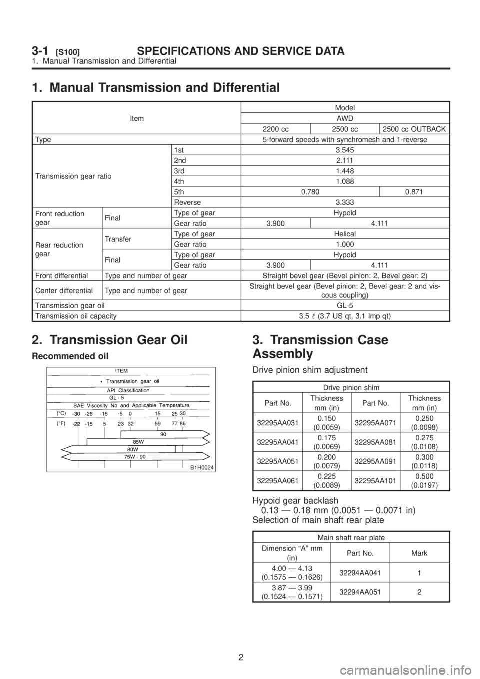
1. Manual Transmission and Differential
ItemModel
AWD
2200 cc 2500 cc 2500 cc OUTBACK
Type 5-forward speeds with synchromesh and 1-reverse
Transmission gear ratio1st 3.545
2nd 2.111
3rd 1.448
4th 1.088
5th 0.780 0.871
Reverse 3.333
Front reduction
gearFinalType of gear Hypoid
Gear ratio 3.900 4.111
Rear reduction
gearTransferType of gear Helical
Gear ratio 1.000
FinalType of gear Hypoid
Gear ratio 3.900 4.111
Front differential Type and number of gear Straight bevel gear (Bevel pinion: 2, Bevel gear: 2)
Center differential Type and number of gearStraight bevel gear (Bevel pinion: 2, Bevel gear: 2 and vis-
cous coupling)
Transmission gear oilGL-5
Transmission oil capacity 3.5(3.7 US qt, 3.1 Imp qt)
2. Transmission Gear Oil
Recommended oil
B1H0024
3. Transmission Case
Assembly
Drive pinion shim adjustment
Drive pinion shim
Part No.Thickness
mm (in)Part No.Thickness
mm (in)
32295AA0310.150
(0.0059)32295AA0710.250
(0.0098)
32295AA0410.175
(0.0069)32295AA0810.275
(0.0108)
32295AA0510.200
(0.0079)32295AA0910.300
(0.0118)
32295AA0610.225
(0.0089)32295AA1010.500
(0.0197)
Hypoid gear backlash
0.13 Ð 0.18 mm (0.0051 Ð 0.0071 in)
Selection of main shaft rear plate
Main shaft rear plate
Dimension ªAº mm
(in)Part No. Mark
4.00 Ð 4.13
(0.1575 Ð 0.1626)32294AA041 1
3.87 Ð 3.99
(0.1524 Ð 0.1571)32294AA051 2
2
3-1[S100]SPECIFICATIONS AND SERVICE DATA
1. Manual Transmission and Differential
Page 466 of 1456

1. Manual Transmission and Differential
ItemModel
AWD
2200 cc 2500 cc 2500 cc OUTBACK
Type 5-forward speeds with synchromesh and 1-reverse
Transmission gear ratio1st 3.545
2nd 2.111
3rd 1.448
4th 1.088
5th 0.780 0.871
Reverse 3.333
Front reduction
gearFinalType of gear Hypoid
Gear ratio 3.900 4.111
Rear reduction
gearTransferType of gear Helical
Gear ratio 1.000
FinalType of gear Hypoid
Gear ratio 3.900 4.111
Front differential Type and number of gear Straight bevel gear (Bevel pinion: 2, Bevel gear: 2)
Center differential Type and number of gearStraight bevel gear (Bevel pinion: 2, Bevel gear: 2 and vis-
cous coupling)
Transmission gear oilGL-5
Transmission oil capacity 3.5(3.7 US qt, 3.1 Imp qt)
2. Transmission Gear Oil
Recommended oil
B1H0024
3. Transmission Case
Assembly
Drive pinion shim adjustment
Drive pinion shim
Part No.Thickness
mm (in)Part No.Thickness
mm (in)
32295AA0310.150
(0.0059)32295AA0710.250
(0.0098)
32295AA0410.175
(0.0069)32295AA0810.275
(0.0108)
32295AA0510.200
(0.0079)32295AA0910.300
(0.0118)
32295AA0610.225
(0.0089)32295AA1010.500
(0.0197)
Hypoid gear backlash
0.13 Ð 0.18 mm (0.0051 Ð 0.0071 in)
Selection of main shaft rear plate
Main shaft rear plate
Dimension ªAº mm
(in)Part No. Mark
4.00 Ð 4.13
(0.1575 Ð 0.1626)32294AA041 1
3.87 Ð 3.99
(0.1524 Ð 0.1571)32294AA051 2
2
3-1[S100]SPECIFICATIONS AND SERVICE DATA
1. Manual Transmission and Differential
Page 467 of 1456

1. Manual Transmission and Differential
ItemModel
AWD
2200 cc 2500 cc 2500 cc OUTBACK
Type 5-forward speeds with synchromesh and 1-reverse
Transmission gear ratio1st 3.545
2nd 2.111
3rd 1.448
4th 1.088
5th 0.780 0.871
Reverse 3.333
Front reduction
gearFinalType of gear Hypoid
Gear ratio 3.900 4.111
Rear reduction
gearTransferType of gear Helical
Gear ratio 1.000
FinalType of gear Hypoid
Gear ratio 3.900 4.111
Front differential Type and number of gear Straight bevel gear (Bevel pinion: 2, Bevel gear: 2)
Center differential Type and number of gearStraight bevel gear (Bevel pinion: 2, Bevel gear: 2 and vis-
cous coupling)
Transmission gear oilGL-5
Transmission oil capacity 3.5(3.7 US qt, 3.1 Imp qt)
2. Transmission Gear Oil
Recommended oil
B1H0024
3. Transmission Case
Assembly
Drive pinion shim adjustment
Drive pinion shim
Part No.Thickness
mm (in)Part No.Thickness
mm (in)
32295AA0310.150
(0.0059)32295AA0710.250
(0.0098)
32295AA0410.175
(0.0069)32295AA0810.275
(0.0108)
32295AA0510.200
(0.0079)32295AA0910.300
(0.0118)
32295AA0610.225
(0.0089)32295AA1010.500
(0.0197)
Hypoid gear backlash
0.13 Ð 0.18 mm (0.0051 Ð 0.0071 in)
Selection of main shaft rear plate
Main shaft rear plate
Dimension ªAº mm
(in)Part No. Mark
4.00 Ð 4.13
(0.1575 Ð 0.1626)32294AA041 1
3.87 Ð 3.99
(0.1524 Ð 0.1571)32294AA051 2
2
3-1[S100]SPECIFICATIONS AND SERVICE DATA
1. Manual Transmission and Differential
Page 472 of 1456

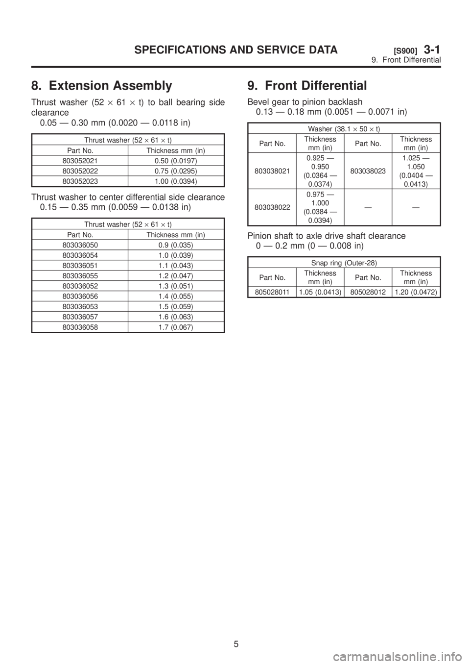
8. Extension Assembly
Thrust washer (52´61´t) to ball bearing side
clearance
0.05 Ð 0.30 mm (0.0020 Ð 0.0118 in)
Thrust washer (52´61´t)
Part No. Thickness mm (in)
803052021 0.50 (0.0197)
803052022 0.75 (0.0295)
803052023 1.00 (0.0394)
Thrust washer to center differential side clearance
0.15 Ð 0.35 mm (0.0059 Ð 0.0138 in)
Thrust washer (52´61´t)
Part No. Thickness mm (in)
803036050 0.9 (0.035)
803036054 1.0 (0.039)
803036051 1.1 (0.043)
803036055 1.2 (0.047)
803036052 1.3 (0.051)
803036056 1.4 (0.055)
803036053 1.5 (0.059)
803036057 1.6 (0.063)
803036058 1.7 (0.067)
9. Front Differential
Bevel gear to pinion backlash
0.13 Ð 0.18 mm (0.0051 Ð 0.0071 in)
Washer (38.1´50´t)
Part No.Thickness
mm (in)Part No.Thickness
mm (in)
8030380210.925 Ð
0.950
(0.0364 Ð
0.0374)8030380231.025 Ð
1.050
(0.0404 Ð
0.0413)
8030380220.975 Ð
1.000
(0.0384 Ð
0.0394)ÐÐ
Pinion shaft to axle drive shaft clearance
0 Ð 0.2 mm (0 Ð 0.008 in)
Snap ring (Outer-28)
Part No.Thickness
mm (in)Part No.Thickness
mm (in)
805028011 1.05 (0.0413) 805028012 1.20 (0.0472)
5
[S900]3-1SPECIFICATIONS AND SERVICE DATA
9. Front Differential