1999 NISSAN PRIMERA warning light
[x] Cancel search: warning lightPage 211 of 2267
pA
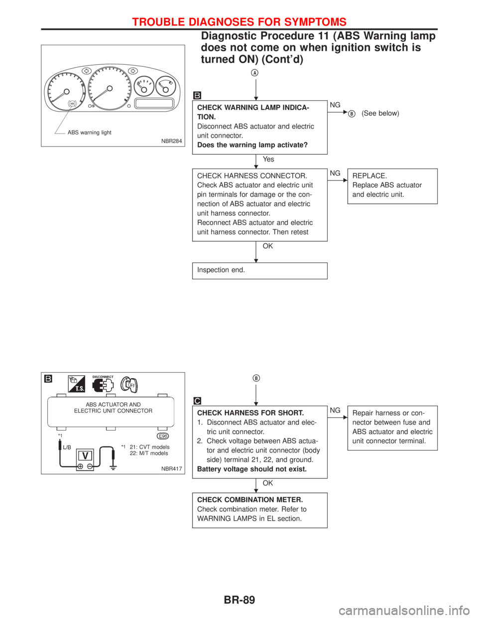
CHECK WARNING LAMP INDICA-
TION.
Disconnect ABS actuator and electric
unit connector.
Does the warning lamp activate?
Ye s
ENG
pB(See below)
CHECK HARNESS CONNECTOR.
Check ABS actuator and electric unit
pin terminals for damage or the con-
nection of ABS actuator and electric
unit harness connector.
Reconnect ABS actuator and electric
unit harness connector. Then retest
OK
ENG
REPLACE.
Replace ABS actuator
and electric unit.
Inspection end.
pB
CHECK HARNESS FOR SHORT.
1. Disconnect ABS actuator and elec-
tric unit connector.
2. Check voltage between ABS actua-
tor and electric unit connector (body
side) terminal 21, 22, and ground.
Battery voltage should not exist.
OK
ENG
Repair harness or con-
nector between fuse and
ABS actuator and electric
unit connector terminal.
CHECK COMBINATION METER.
Check combination meter. Refer to
WARNING LAMPS in EL section.
NBR284 ABS warning light
NBR417
ABS ACTUATOR AND
ELECTRIC UNIT CONNECTOR
.21: CVT models
22: M/T models
H
H
H
H
H
TROUBLE DIAGNOSES FOR SYMPTOMS
Diagnostic Procedure 11 (ABS Warning lamp
does not come on when ignition switch is
turned ON) (Cont'd)
BR-89
Page 300 of 2267
Supplemental Restraint System (SRS) ªAIR
BAGº and ªSEAT BELT PRE-TENSIONERº
NCEC0002
The Supplemental Restraint System ªAIR BAGº and ªSEAT BELT PRE-TENSIONERº, used along with a seat
belt, help to reduce the risk or severity of injury to the driver and front passenger in a frontal collision. The
Supplemental Restraint System consists of air bag modules (located in the center of the steering wheel and
on the instrument panel on the passenger side), seat belt pre-tensioners, a diagnosis sensor unit, warning
lamp, wiring harness and spiral cable.
In addition to the supplemental air bag modules for a frontal collision, the supplemental side air bag used
along with the seat belt helps to reduce the risk or severity of injury to the driver and front passenger in a
side collision. The supplemental side air bag consists of air bag modules (located in the outer side of front
seats), satellite sensor, diagnosis sensor unit (one of components of supplemental air bags for a frontal
collision), wiring harness, warning lamp (one of components of supplemental air bags for a frontal collision).
Information necessary to service the system safely is included in theRS sectionof this Service Manual.
WARNING:
lTo avoid rendering the SRS inoperative, which could increase the risk of personal injury or death
in the event of a collision which would result in air bag inflation, all maintenance must be per-
formed by an authorized NISSAN dealer.
lImproper maintenance, including incorrect removal and installation of the SRS, can lead to per-
sonal injury caused by unintentional activation of the system.
lDo not use electrical test equipment on any circuit related to the SRS unless instructed to in this
Service Manual. SRS wiring harnesses (except ªSEAT BELT PRE-TENSIONERº connector) can be
identified with yellow harness connector (and with yellow harness protector or yellow insulation
tape before the harness connectors).
Precautions for On Board Diagnostic (OBD)
System of Engine
NCEC0003
The ECM has an on board diagnostic system. It will light up the malfunction indicator (MI) to warn the driver
of a malfunction causing emission deterioration.
CAUTION:
lBe sure to turn the ignition switch ªOFFº and disconnect the negative battery terminal before any
repair or inspection work. The open/short circuit of related switches, sensors, solenoid valves,
etc. will cause the MI to light up.
lBe sure to connect and lock the connectors securely after work. A loose (unlocked) connector
will cause the MI to light up due to the open circuit. (Be sure the connector is free from water,
grease, dirt, bent terminals, etc.)
lCertain systems and components, especially those related to OBD, may use a new style slide-
locking type harness connector.
For description and how to disconnect, refer to EL section, ªDescriptionº, ªHARNESS CONNEC-
TORº.
lBe sure to route and secure the harnesses properly after work. The interference of the harness
with a bracket, etc. may cause the MI to light up due to the short circuit.
lBe sure to connect rubber tubes properly after work. A misconnected or disconnected rubber
tube may cause the MI to light up due to the malfunction of the EGR system or fuel injection
system, etc.
lBe sure to erase the unnecessary malfunction information (repairs completed) from the ECM
before returning the vehicle to the customer.
PRECAUTIONS AND PREPARATIONCD20T
EC-6
Page 451 of 2267
Supplemental Restraint System (SRS) ªAIR
BAGº and ªSEAT BELT PRE-TENSIONERº
NCEC0002The Supplemental Restraint System ªAIR BAGº and ªSEAT BELT PRE-TENSIONERº, used along with a seat
belt, help to reduce the risk or severity of injury to the driver and front passenger in a frontal collision. The
Supplemental Restraint System consists of air bag modules (located in the center of the steering wheel and
on the instrument panel on the passenger side), seat belt pre-tensioners, a diagnosis sensor unit, warning
lamp, wiring harness and spiral cable.
In addition to the supplemental air bag modules for a frontal collision, the supplemental side air bag used along
with the seat belt helps to reduce the risk or severity of injury to the driver and front passenger in a side col-
lision. The supplemental side air bag consists of air bag modules (located in the outer side of front seats),
satellite sensor, diagnosis sensor unit (one of components of supplemental air bags for a frontal collision),
wiring harness, warning lamp (one of components of supplemental air bags for a frontal collision). Information
necessary to service the system safely is included in theRS sectionof this Service Manual.
WARNING:
ITo avoid rendering the SRS inoperative, which could increase the risk of personal injury or death
in the event of a collision which would result in air bag inflation, all maintenance must be performed
by an authorized NISSAN dealer.
IImproper maintenance, including incorrect removal and installation of the SRS, can lead to per-
sonal injury caused by unintentional activation of the system.
IDo not use electrical test equipment on any circuit related to the SRS unless instructed to in this
Service Manual. SRS wiring harnesses (except ªSEAT BELT PRE-TENSIONERº connector) can be
identified with yellow harness connector (and with yellow harness protector or yellow insulation
tape before the harness connectors).
Precautions for On Board Diagnostic (OBD)
System of Engine
NCEC0003The ECM has an on board diagnostic system. It will light up the malfunction indicator (MI) to warn the driver
of a malfunction causing emission deterioration.
CAUTION:
IBe sure to turn the ignition switch ªOFFº and disconnect the negative battery terminal before any
repair or inspection work. The open/short circuit of related switches, sensors, solenoid valves, etc.
will cause the MI to light up.
IBe sure to connect and lock the connectors securely after work. A loose (unlocked) connector will
cause the MI to light up due to the open circuit. (Be sure the connector is free from water, grease,
dirt, bent terminals, etc.)
ICertain systems and components, especially those related to OBD, may use a new style slide-
locking type harness connector.
For description and how to disconnect, refer to EL section, ªDescriptionº, ªHARNESS CONNEC-
TORº.
IBe sure to route and secure the harnesses properly after work. The interference of the harness with
a bracket, etc. may cause the MI to light up due to the short circuit.
IBe sure to connect rubber tubes properly after work. A misconnected or disconnected rubber tube
may cause the MI to light up due to the malfunction of the EGR system or fuel injection system,
etc.
IBe sure to erase the unnecessary malfunction information (repairs completed) from the ECM before
returning the vehicle to the customer.
PRECAUTIONSQG16I18DE
Supplemental Restraint System (SRS) ªAIR BAGº and ªSEAT BELT PRE-TENSIONERº
EC-9
Page 488 of 2267
DESCRIPTIONNCEC0032
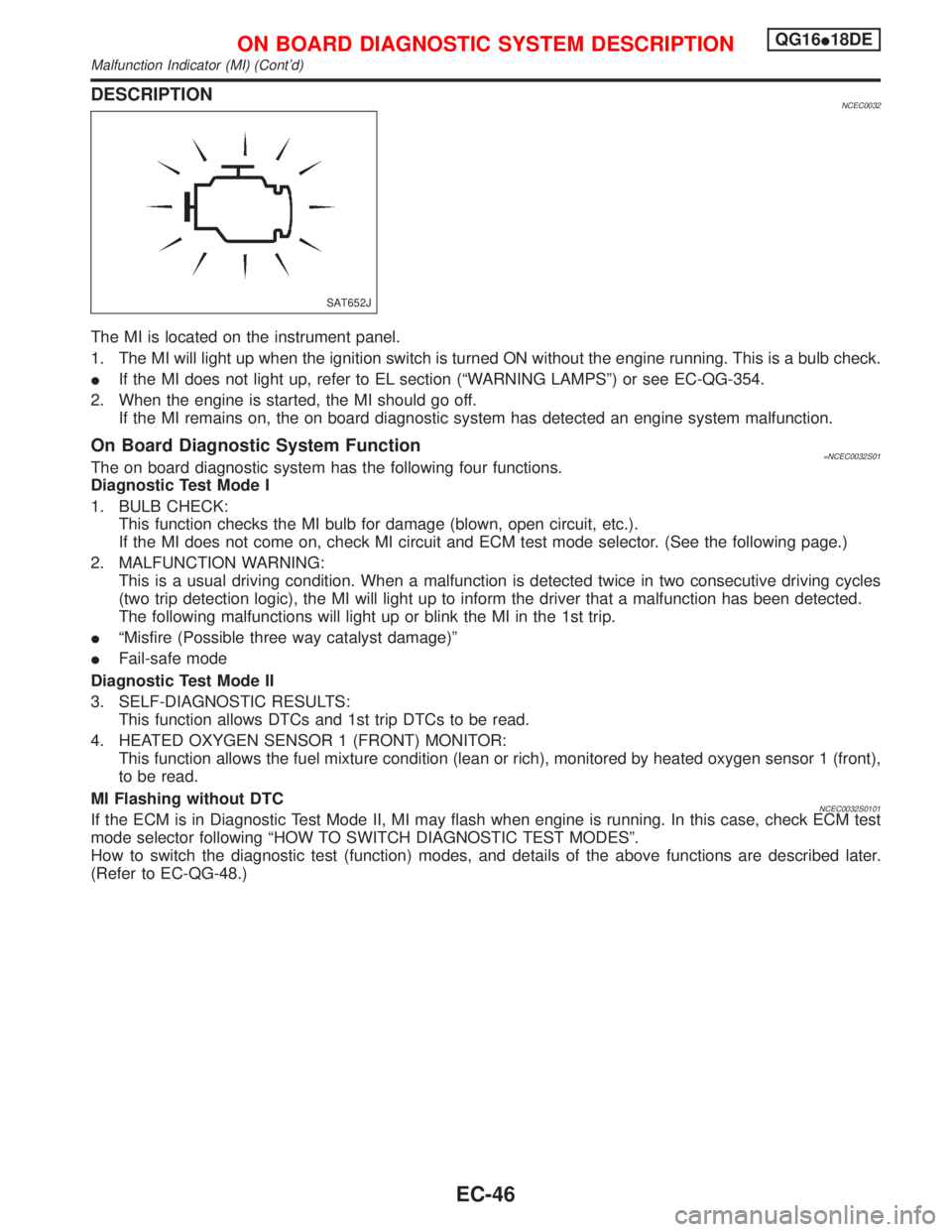
The MI is located on the instrument panel.
1. The MI will light up when the ignition switch is turned ON without the engine running. This is a bulb check.
IIf the MI does not light up, refer to EL section (ªWARNING LAMPSº) or see EC-QG-354.
2. When the engine is started, the MI should go off.
If the MI remains on, the on board diagnostic system has detected an engine system malfunction.
On Board Diagnostic System Function=NCEC0032S01The on board diagnostic system has the following four functions.
Diagnostic Test Mode I
1. BULB CHECK:
This function checks the MI bulb for damage (blown, open circuit, etc.).
If the MI does not come on, check MI circuit and ECM test mode selector. (See the following page.)
2. MALFUNCTION WARNING:
This is a usual driving condition. When a malfunction is detected twice in two consecutive driving cycles
(two trip detection logic), the MI will light up to inform the driver that a malfunction has been detected.
The following malfunctions will light up or blink the MI in the 1st trip.
IªMisfire (Possible three way catalyst damage)º
IFail-safe mode
Diagnostic Test Mode II
3. SELF-DIAGNOSTIC RESULTS:
This function allows DTCs and 1st trip DTCs to be read.
4. HEATED OXYGEN SENSOR 1 (FRONT) MONITOR:
This function allows the fuel mixture condition (lean or rich), monitored by heated oxygen sensor 1 (front),
to be read.
MI Flashing without DTC
NCEC0032S0101If the ECM is in Diagnostic Test Mode II, MI may flash when engine is running. In this case, check ECM test
mode selector following ªHOW TO SWITCH DIAGNOSTIC TEST MODESº.
How to switch the diagnostic test (function) modes, and details of the above functions are described later.
(Refer to EC-QG-48.)
SAT652J
ON BOARD DIAGNOSTIC SYSTEM DESCRIPTIONQG16I18DE
Malfunction Indicator (MI) (Cont'd)
EC-46
Page 810 of 2267
Supplemental Restraint System (SRS) ªAIR
BAGº and ªSEAT BELT PRE-TENSIONERº
NCEC0002The Supplemental Restraint System ªAIR BAGº and ªSEAT BELT PRE-TENSIONERº, used along with a seat
belt, help to reduce the risk or severity of injury to the driver and front passenger in a frontal collision. The
Supplemental Restraint System consists of air bag modules (located in the center of the steering wheel and
on the instrument panel on the passenger side), seat belt pre-tensioners, a diagnosis sensor unit, warning
lamp, wiring harness and spiral cable.
In addition to the supplemental air bag modules for a frontal collision, the supplemental side air bag used along
with the seat belt helps to reduce the risk or severity of injury to the driver and front passenger in a side col-
lision. The supplemental side air bag consists of air bag modules (located in the outer side of front seats),
satellite sensor, diagnosis sensor unit (one of components of supplemental air bags for a frontal collision),
wiring harness, warning lamp (one of components of supplemental air bags for a frontal collision). Information
necessary to service the system safely is included in theRS sectionof this Service Manual.
WARNING:
ITo avoid rendering the SRS inoperative, which could increase the risk of personal injury or death
in the event of a collision which would result in air bag inflation, all maintenance must be performed
by an authorized NISSAN dealer.
IImproper maintenance, including incorrect removal and installation of the SRS, can lead to per-
sonal injury caused by unintentional activation of the system.
IDo not use electrical test equipment on any circuit related to the SRS unless instructed to in this
Service Manual. SRS wiring harnesses (except ªSEAT BELT PRE-TENSIONERº connector) can be
identified with yellow harness connector (and with yellow harness protector or yellow insulation
tape before the harness connectors).
Precautions for On Board Diagnostic (OBD)
System of Engine and CVT
NCEC0003The ECM has an on board diagnostic system. It will light up the malfunction indicator (MI) to warn the driver
of a malfunction causing emission deterioration.
CAUTION:
IBe sure to turn the ignition switch ªOFFº and disconnect the negative battery terminal before any
repair or inspection work. The open/short circuit of related switches, sensors, solenoid valves, etc.
will cause the MI to light up.
IBe sure to connect and lock the connectors securely after work. A loose (unlocked) connector will
cause the MI to light up due to the open circuit. (Be sure the connector is free from water, grease,
dirt, bent terminals, etc.)
ICertain systems and components, especially those related to OBD, may use a new style slide-
locking type harness connector.
For description and how to disconnect, refer to EL section, ªDescriptionº, ªHARNESS CONNEC-
TORº.
IBe sure to route and secure the harnesses properly after work. The interference of the harness with
a bracket, etc. may cause the MI to light up due to the short circuit.
IBe sure to connect rubber tubes properly after work. A misconnected or disconnected rubber tube
may cause the MI to light up due to the malfunction of the fuel injection system, etc.
IBe sure to erase the unnecessary malfunction information (repairs completed) from the ECM and
TCM (Transmission Control Module) before returning the vehicle to the customer.
PRECAUTIONSSR20DE
Supplemental Restraint System (SRS) ªAIR BAGº and ªSEAT BELT PRE-TENSIONERº
EC-10
Page 859 of 2267
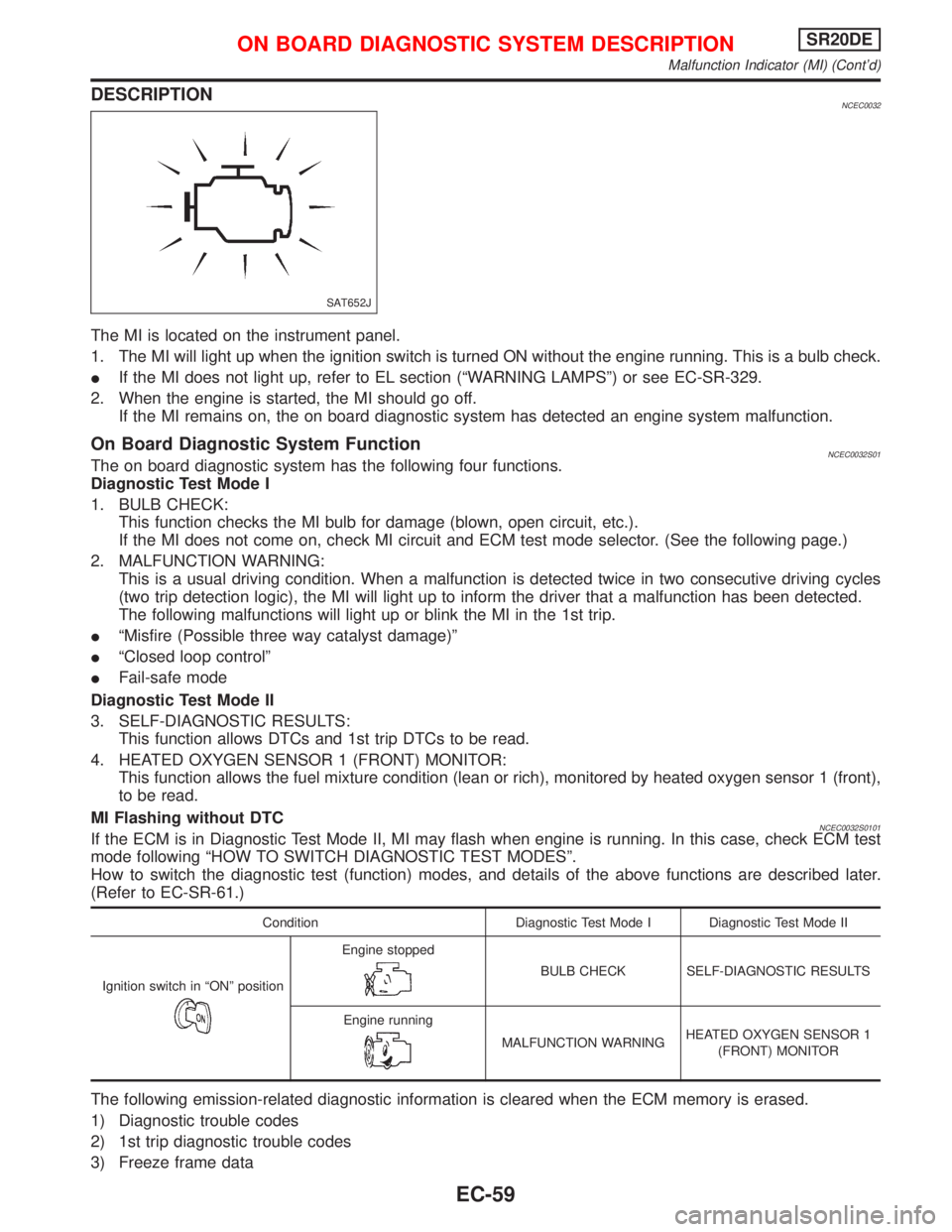
DESCRIPTIONNCEC0032
The MI is located on the instrument panel.
1. The MI will light up when the ignition switch is turned ON without the engine running. This is a bulb check.
IIf the MI does not light up, refer to EL section (ªWARNING LAMPSº) or see EC-SR-329.
2. When the engine is started, the MI should go off.
If the MI remains on, the on board diagnostic system has detected an engine system malfunction.
On Board Diagnostic System FunctionNCEC0032S01The on board diagnostic system has the following four functions.
Diagnostic Test Mode I
1. BULB CHECK:
This function checks the MI bulb for damage (blown, open circuit, etc.).
If the MI does not come on, check MI circuit and ECM test mode selector. (See the following page.)
2. MALFUNCTION WARNING:
This is a usual driving condition. When a malfunction is detected twice in two consecutive driving cycles
(two trip detection logic), the MI will light up to inform the driver that a malfunction has been detected.
The following malfunctions will light up or blink the MI in the 1st trip.
IªMisfire (Possible three way catalyst damage)º
IªClosed loop controlº
IFail-safe mode
Diagnostic Test Mode II
3. SELF-DIAGNOSTIC RESULTS:
This function allows DTCs and 1st trip DTCs to be read.
4. HEATED OXYGEN SENSOR 1 (FRONT) MONITOR:
This function allows the fuel mixture condition (lean or rich), monitored by heated oxygen sensor 1 (front),
to be read.
MI Flashing without DTC
NCEC0032S0101If the ECM is in Diagnostic Test Mode II, MI may flash when engine is running. In this case, check ECM test
mode following ªHOW TO SWITCH DIAGNOSTIC TEST MODESº.
How to switch the diagnostic test (function) modes, and details of the above functions are described later.
(Refer to EC-SR-61.)
Condition Diagnostic Test Mode I Diagnostic Test Mode II
Ignition switch in ªONº position
Engine stopped
BULB CHECK SELF-DIAGNOSTIC RESULTS
Engine running
MALFUNCTION WARNINGHEATED OXYGEN SENSOR 1
(FRONT) MONITOR
The following emission-related diagnostic information is cleared when the ECM memory is erased.
1) Diagnostic trouble codes
2) 1st trip diagnostic trouble codes
3) Freeze frame data
SAT652J
ON BOARD DIAGNOSTIC SYSTEM DESCRIPTIONSR20DE
Malfunction Indicator (MI) (Cont'd)
EC-59
Page 1134 of 2267
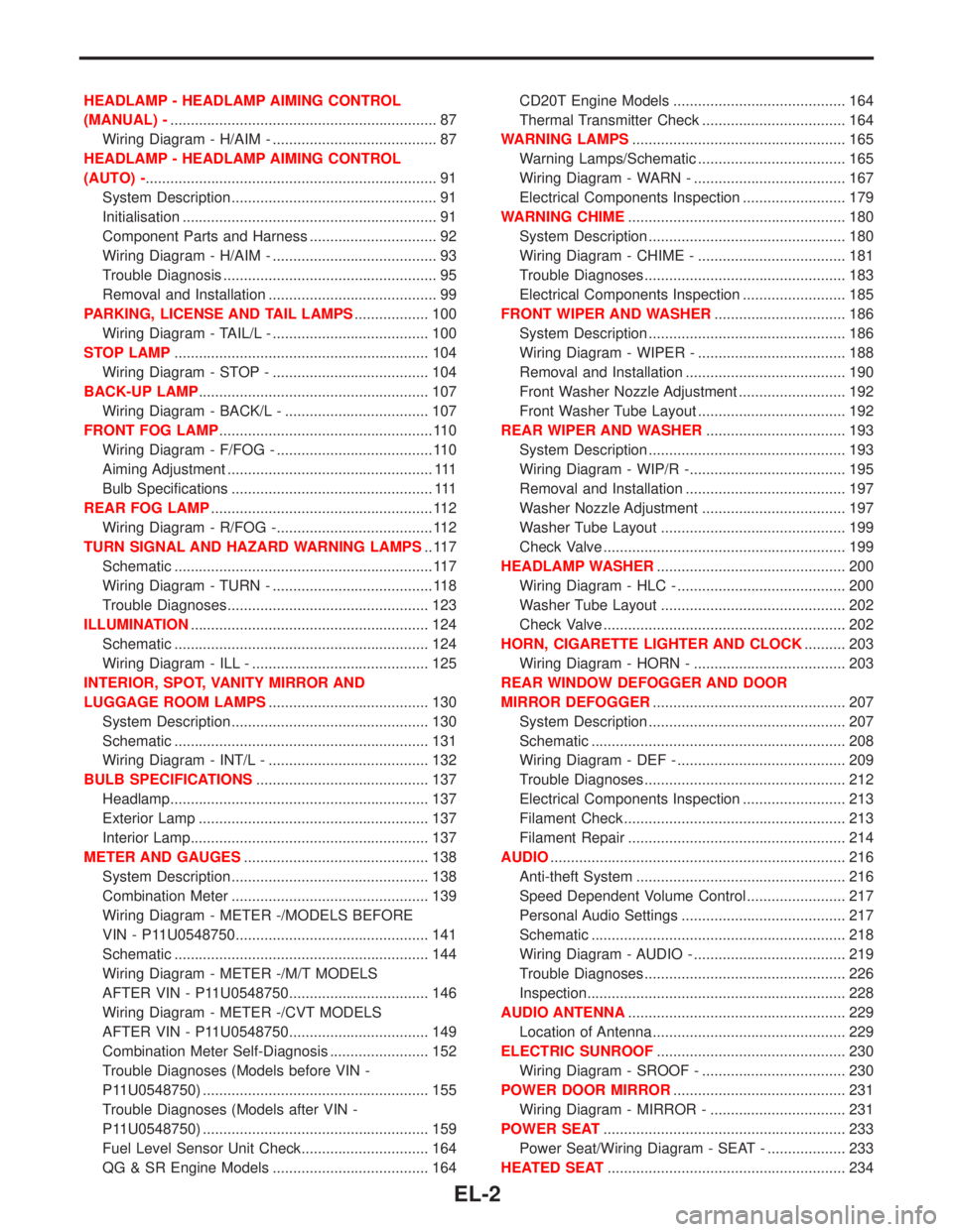
HEADLAMP - HEADLAMP AIMING CONTROL
(MANUAL) -................................................................. 87
Wiring Diagram - H/AIM - ........................................ 87
HEADLAMP - HEADLAMP AIMING CONTROL
(AUTO) -....................................................................... 91
System Description .................................................. 91
Initialisation .............................................................. 91
Component Parts and Harness ............................... 92
Wiring Diagram - H/AIM - ........................................ 93
Trouble Diagnosis .................................................... 95
Removal and Installation ......................................... 99
PARKING, LICENSE AND TAIL LAMPS.................. 100
Wiring Diagram - TAIL/L - ...................................... 100
STOP LAMP.............................................................. 104
Wiring Diagram - STOP - ...................................... 104
BACK-UP LAMP........................................................ 107
Wiring Diagram - BACK/L - ................................... 107
FRONT FOG LAMP.................................................... 110
Wiring Diagram - F/FOG - ...................................... 110
Aiming Adjustment .................................................. 111
Bulb Specifications ................................................. 111
REAR FOG LAMP...................................................... 112
Wiring Diagram - R/FOG -...................................... 112
TURN SIGNAL AND HAZARD WARNING LAMPS.. 117
Schematic ............................................................... 117
Wiring Diagram - TURN - ....................................... 118
Trouble Diagnoses................................................. 123
ILLUMINATION.......................................................... 124
Schematic .............................................................. 124
Wiring Diagram - ILL - ........................................... 125
INTERIOR, SPOT, VANITY MIRROR AND
LUGGAGE ROOM LAMPS....................................... 130
System Description ................................................ 130
Schematic .............................................................. 131
Wiring Diagram - INT/L - ....................................... 132
BULB SPECIFICATIONS.......................................... 137
Headlamp............................................................... 137
Exterior Lamp ........................................................ 137
Interior Lamp.......................................................... 137
METER AND GAUGES............................................. 138
System Description ................................................ 138
Combination Meter ................................................ 139
Wiring Diagram - METER -/MODELS BEFORE
VIN - P11U0548750............................................... 141
Schematic .............................................................. 144
Wiring Diagram - METER -/M/T MODELS
AFTER VIN - P11U0548750.................................. 146
Wiring Diagram - METER -/CVT MODELS
AFTER VIN - P11U0548750.................................. 149
Combination Meter Self-Diagnosis ........................ 152
Trouble Diagnoses (Models before VIN -
P11U0548750) ....................................................... 155
Trouble Diagnoses (Models after VIN -
P11U0548750) ....................................................... 159
Fuel Level Sensor Unit Check............................... 164
QG & SR Engine Models ...................................... 164CD20T Engine Models .......................................... 164
Thermal Transmitter Check ................................... 164
WARNING LAMPS.................................................... 165
Warning Lamps/Schematic .................................... 165
Wiring Diagram - WARN - ..................................... 167
Electrical Components Inspection ......................... 179
WARNING CHIME..................................................... 180
System Description ................................................ 180
Wiring Diagram - CHIME - .................................... 181
Trouble Diagnoses................................................. 183
Electrical Components Inspection ......................... 185
FRONT WIPER AND WASHER................................ 186
System Description ................................................ 186
Wiring Diagram - WIPER - .................................... 188
Removal and Installation ....................................... 190
Front Washer Nozzle Adjustment .......................... 192
Front Washer Tube Layout .................................... 192
REAR WIPER AND WASHER.................................. 193
System Description ................................................ 193
Wiring Diagram - WIP/R -...................................... 195
Removal and Installation ....................................... 197
Washer Nozzle Adjustment ................................... 197
Washer Tube Layout ............................................. 199
Check Valve ........................................................... 199
HEADLAMP WASHER.............................................. 200
Wiring Diagram - HLC - ......................................... 200
Washer Tube Layout ............................................. 202
Check Valve ........................................................... 202
HORN, CIGARETTE LIGHTER AND CLOCK.......... 203
Wiring Diagram - HORN - ..................................... 203
REAR WINDOW DEFOGGER AND DOOR
MIRROR DEFOGGER............................................... 207
System Description ................................................ 207
Schematic .............................................................. 208
Wiring Diagram - DEF - ......................................... 209
Trouble Diagnoses................................................. 212
Electrical Components Inspection ......................... 213
Filament Check ...................................................... 213
Filament Repair ..................................................... 214
AUDIO........................................................................ 216
Anti-theft System ................................................... 216
Speed Dependent Volume Control ........................ 217
Personal Audio Settings ........................................ 217
Schematic .............................................................. 218
Wiring Diagram - AUDIO - ..................................... 219
Trouble Diagnoses................................................. 226
Inspection............................................................... 228
AUDIO ANTENNA..................................................... 229
Location of Antenna ............................................... 229
ELECTRIC SUNROOF.............................................. 230
Wiring Diagram - SROOF - ................................... 230
POWER DOOR MIRROR.......................................... 231
Wiring Diagram - MIRROR - ................................. 231
POWER SEAT........................................................... 233
Power Seat/Wiring Diagram - SEAT - ................... 233
HEATED SEAT.......................................................... 234
EL-2
Page 1155 of 2267
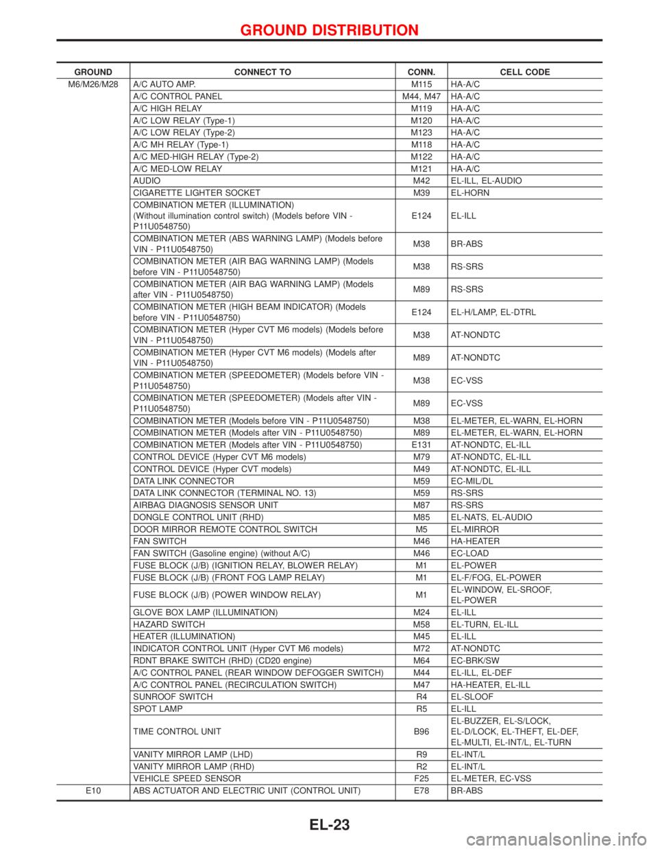
GROUND CONNECT TO CONN. CELL CODE
M6/M26/M28 A/C AUTO AMP. M115 HA-A/C
A/C CONTROL PANEL M44, M47 HA-A/C
A/C HIGH RELAY M119 HA-A/C
A/C LOW RELAY (Type-1) M120 HA-A/C
A/C LOW RELAY (Type-2) M123 HA-A/C
A/C MH RELAY (Type-1) M118 HA-A/C
A/C MED-HIGH RELAY (Type-2) M122 HA-A/C
A/C MED-LOW RELAY M121 HA-A/C
AUDIO M42 EL-ILL, EL-AUDIO
CIGARETTE LIGHTER SOCKET M39 EL-HORN
COMBINATION METER (ILLUMINATION)
(Without illumination control switch) (Models before VIN -
P11U0548750)E124 EL-ILL
COMBINATION METER (ABS WARNING LAMP) (Models before
VIN - P11U0548750)M38 BR-ABS
COMBINATION METER (AIR BAG WARNING LAMP) (Models
before VIN - P11U0548750)M38 RS-SRS
COMBINATION METER (AIR BAG WARNING LAMP) (Models
after VIN - P11U0548750)M89 RS-SRS
COMBINATION METER (HIGH BEAM INDICATOR) (Models
before VIN - P11U0548750)E124 EL-H/LAMP, EL-DTRL
COMBINATION METER (Hyper CVT M6 models) (Models before
VIN - P11U0548750)M38 AT-NONDTC
COMBINATION METER (Hyper CVT M6 models) (Models after
VIN - P11U0548750)M89 AT-NONDTC
COMBINATION METER (SPEEDOMETER) (Models before VIN -
P11U0548750)M38 EC-VSS
COMBINATION METER (SPEEDOMETER) (Models after VIN -
P11U0548750)M89 EC-VSS
COMBINATION METER (Models before VIN - P11U0548750) M38 EL-METER, EL-WARN, EL-HORN
COMBINATION METER (Models after VIN - P11U0548750) M89 EL-METER, EL-WARN, EL-HORN
COMBINATION METER (Models after VIN - P11U0548750) E131 AT-NONDTC, EL-ILL
CONTROL DEVICE (Hyper CVT M6 models) M79 AT-NONDTC, EL-ILL
CONTROL DEVICE (Hyper CVT models) M49 AT-NONDTC, EL-ILL
DATA LINK CONNECTOR M59 EC-MIL/DL
DATA LINK CONNECTOR (TERMINAL NO. 13) M59 RS-SRS
AIRBAG DIAGNOSIS SENSOR UNIT M87 RS-SRS
DONGLE CONTROL UNIT (RHD) M85 EL-NATS, EL-AUDIO
DOOR MIRROR REMOTE CONTROL SWITCH M5 EL-MIRROR
FAN SWITCH M46 HA-HEATER
FAN SWITCH (Gasoline engine) (without A/C) M46 EC-LOAD
FUSE BLOCK (J/B) (IGNITION RELAY, BLOWER RELAY) M1 EL-POWER
FUSE BLOCK (J/B) (FRONT FOG LAMP RELAY) M1 EL-F/FOG, EL-POWER
FUSE BLOCK (J/B) (POWER WINDOW RELAY) M1EL-WINDOW, EL-SROOF,
EL-POWER
GLOVE BOX LAMP (ILLUMINATION) M24 EL-ILL
HAZARD SWITCH M58 EL-TURN, EL-ILL
HEATER (ILLUMINATION) M45 EL-ILL
INDICATOR CONTROL UNIT (Hyper CVT M6 models) M72 AT-NONDTC
RDNT BRAKE SWITCH (RHD) (CD20 engine) M64 EC-BRK/SW
A/C CONTROL PANEL (REAR WINDOW DEFOGGER SWITCH) M44 EL-ILL, EL-DEF
A/C CONTROL PANEL (RECIRCULATION SWITCH) M47 HA-HEATER, EL-ILL
SUNROOF SWITCH R4 EL-SLOOF
SPOT LAMP R5 EL-ILL
TIME CONTROL UNIT B96EL-BUZZER, EL-S/LOCK,
EL-D/LOCK, EL-THEFT, EL-DEF,
EL-MULTI, EL-INT/L, EL-TURN
VANITY MIRROR LAMP (LHD) R9 EL-INT/L
VANITY MIRROR LAMP (RHD) R2 EL-INT/L
VEHICLE SPEED SENSOR F25 EL-METER, EC-VSS
E10 ABS ACTUATOR AND ELECTRIC UNIT (CONTROL UNIT) E78 BR-ABS
GROUND DISTRIBUTION
EL-23