1999 NISSAN PRIMERA sensor
[x] Cancel search: sensorPage 17 of 2267
IntroductionNCAT0017The CVT system has two self-diagnostic systems.
The first is the emission-related on board diagnostic system (OBD) performed by the TCM in combination with
the ECM. The malfunction is indicated by the MI (malfunction indicator) and is stored as a DTC in the ECM
memory but not the TCM memory.
The second is the TCM original self-diagnosis indicated by the CVT indicator (warning) lamp or SPORT indi-
cator lamp. The malfunction is stored in the TCM memory. The detected items are overlapped with OBD self-
diagnostic items. For detail, refer to AT-26.
OBD Function for CVT SystemNCAT0018The ECM provides emission-related on board diagnostic (OBD) functions for the CVT system. One function
is to receive a signal from the TCM used with OBD-related parts of the CVT system. The signal is sent to the
ECM when a malfunction occurs in the corresponding OBD-related part. The other function is to indicate a
diagnostic result by means of the MI (malfunction indicator) on the instrument panel. Sensors, switches and
solenoid valves are used as sensing elements.
The MI automatically illuminates in Two Trip Detection Logic when a malfunction is sensed in relation to CVT
system parts.
OBD Diagnostic Trouble Code (DTC)NCAT0020HOW TO READ DTC AND 1ST TRIP DTCNCAT0020S01DTC and 1st trip DTC can be read by the following methods.
1.(
No Tools)The number of blinks of the malfunction indicator in the Diagnostic Test Mode II (Self-Di-
agnostic Results) Examples: 0705, 0710, 0715, 0720, etc. For details, refer to EC section [ªMalfunction
Indicator (MI)º, ªON BOARD DIAGNOSTIC SYSTEM DESCRIPTIONº].
These DTCs are controlled by NISSAN.
2.(
with CONSULT-II orGST)CONSULT-II or GST (Generic Scan Tool) Examples: P0705, P0710,
P0720, P0725, etc.
These DTCs are prescribed by ISO15031-6.
(CONSULT-II also displays the malfunctioning component or system.)
I1st trip DTC No. is the same as DTC No.
IOutput of the diagnostic trouble code indicates that the indicated circuit has a malfunction.
However, in case of the Mode II and GST they do not indicate whether the malfunction is still
occurring or occurred in the past and returned to normal.
CONSULT-II can identify them as shown below. Therefore, using CONSULT-II (if available) is rec-
ommended.
A sample of CONSULT-II display for DTC is shown at left. DTC or 1st trip DTC of a malfunction is displayed
in SELF-DIAGNOSTIC RESULTS mode for ªENGINEº with CONSULT-II. Time data indicates how many times
the vehicle was driven after the last detection of a DTC.
If the DTC is being detected currently, the time data will be ª0º.
SAT651J
ON BOARD DIAGNOSTIC SYSTEM DESCRIPTION
Introduction
AT-15
Page 21 of 2267
SELF-DIAGNOSTIC PROCEDURE
(WITH CONSULT-II)
NCAT0022S021. Turn on CONSULT-II and touch ªENGINEº for OBD detected
items or touch ªCVTº for TCM self-diagnosis.
If CVT is not displayed, check TCM power supply and ground
circuit. Refer to AT-41. If result is NG, refer to EL section
(ªPOWER SUPPLY ROUTINGº).
2. Touch ªSELF DIAGNOSISº.
Display shows malfunction experienced since the last erasing
operation.
CONSULT-II performs REAL-TIME SELF-DIAGNOSIS.
Also, any malfunction detected while in this mode will be dis-
played at real time.
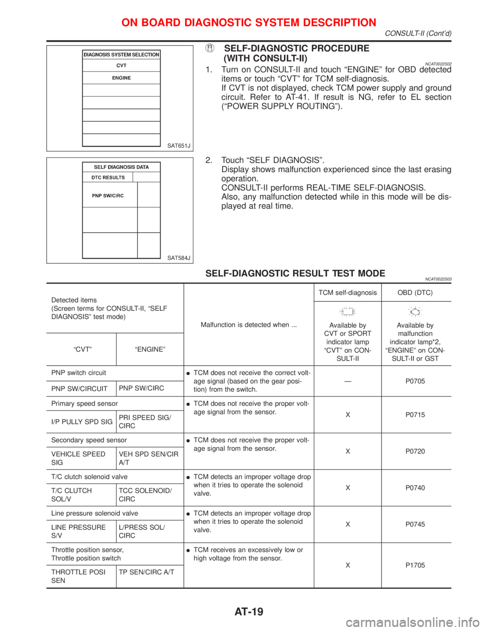
SELF-DIAGNOSTIC RESULT TEST MODENCAT0022S03
Detected items
(Screen terms for CONSULT-II, ªSELF
DIAGNOSISº test mode)
Malfunction is detected when ...TCM self-diagnosis OBD (DTC)
Available by
CVT or SPORT
indicator lamp
ªCVTº on CON-
SULT-IIAvailable by
malfunction
indicator lamp*2,
ªENGINEº on CON-
SULT-II or GST ªCVTº ªENGINEº
PNP switch circuitITCM does not receive the correct volt-
age signal (based on the gear posi-
tion) from the switch.Ð P0705
PNP SW/CIRCUITPNP SW/CIRC
Primary speed sensorITCM does not receive the proper volt-
age signal from the sensor.
X P0715
I/P PULLY SPD SIGPRI SPEED SIG/
CIRC
Secondary speed sensorITCM does not receive the proper volt-
age signal from the sensor.
X P0720
VEHICLE SPEED
SIGVEH SPD SEN/CIR
A/T
T/C clutch solenoid valveITCM detects an improper voltage drop
when it tries to operate the solenoid
valve.X P0740
T/C CLUTCH
SOL/VTCC SOLENOID/
CIRC
Line pressure solenoid valveITCM detects an improper voltage drop
when it tries to operate the solenoid
valve.X P0745
LINE PRESSURE
S/VL/PRESS SOL/
CIRC
Throttle position sensor,
Throttle position switchITCM receives an excessively low or
high voltage from the sensor.
X P1705
THROTTLE POSI
SENTP SEN/CIRC A/T
SAT651J
SAT584J
ON BOARD DIAGNOSTIC SYSTEM DESCRIPTION
CONSULT-II (Cont'd)
AT-19
Page 22 of 2267
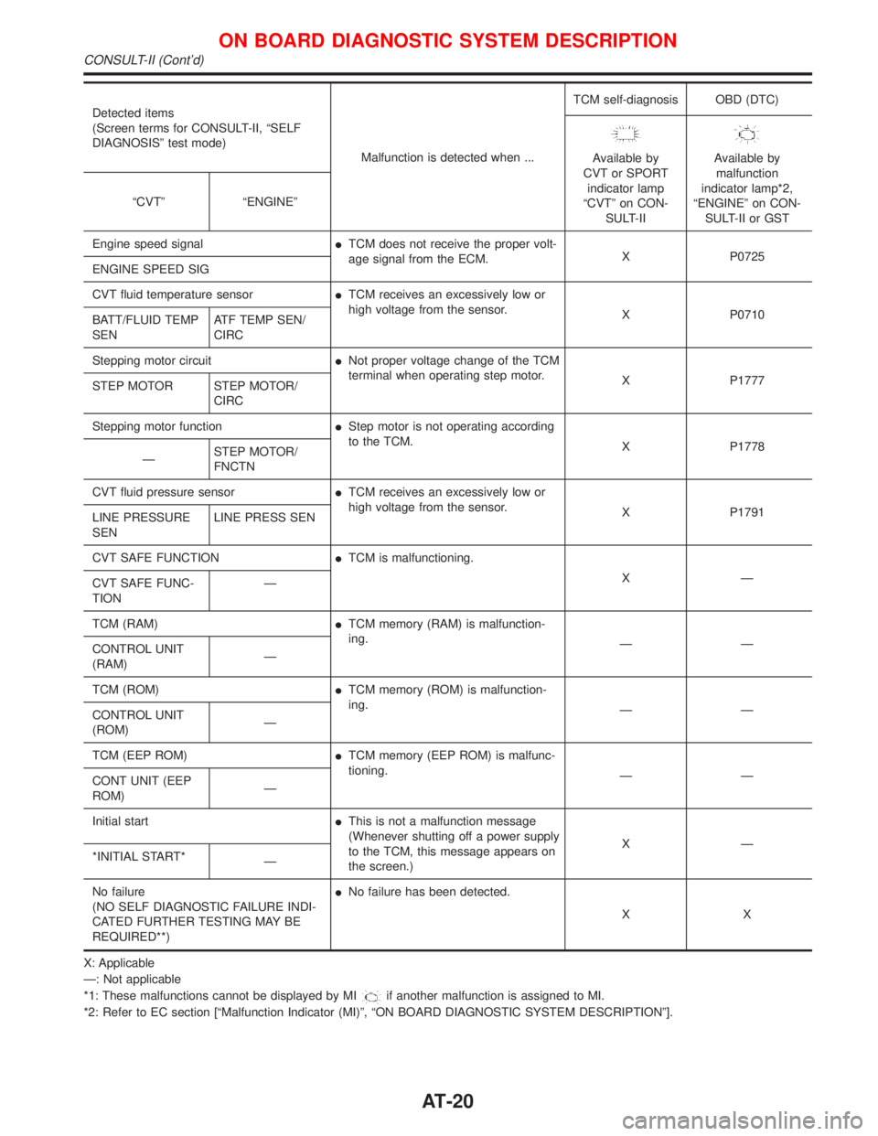
Detected items
(Screen terms for CONSULT-II, ªSELF
DIAGNOSISº test mode)
Malfunction is detected when ...TCM self-diagnosis OBD (DTC)
Available by
CVT or SPORT
indicator lamp
ªCVTº on CON-
SULT-IIAvailable by
malfunction
indicator lamp*2,
ªENGINEº on CON-
SULT-II or GST ªCVTº ªENGINEº
Engine speed signalITCM does not receive the proper volt-
age signal from the ECM.X P0725
ENGINE SPEED SIG
CVT fluid temperature sensorITCM receives an excessively low or
high voltage from the sensor.
X P0710
BATT/FLUID TEMP
SENATF TEMP SEN/
CIRC
Stepping motor circuitINot proper voltage change of the TCM
terminal when operating step motor.
X P1777
STEP MOTOR STEP MOTOR/
CIRC
Stepping motor functionIStep motor is not operating according
to the TCM.
X P1778
ÐSTEP MOTOR/
FNCTN
CVT fluid pressure sensorITCM receives an excessively low or
high voltage from the sensor.
X P1791
LINE PRESSURE
SENLINE PRESS SEN
CVT SAFE FUNCTIONITCM is malfunctioning.
XÐ
CVT SAFE FUNC-
TIONÐ
TCM (RAM)ITCM memory (RAM) is malfunction-
ing.
ÐÐ
CONTROL UNIT
(RAM)Ð
TCM (ROM)ITCM memory (ROM) is malfunction-
ing.
ÐÐ
CONTROL UNIT
(ROM)Ð
TCM (EEP ROM)ITCM memory (EEP ROM) is malfunc-
tioning.
ÐÐ
CONT UNIT (EEP
ROM)Ð
Initial startIThis is not a malfunction message
(Whenever shutting off a power supply
to the TCM, this message appears on
the screen.)XÐ
*INITIAL START*
Ð
No failure
(NO SELF DIAGNOSTIC FAILURE INDI-
CATED FURTHER TESTING MAY BE
REQUIRED**)INo failure has been detected.
XX
X: Applicable
Ð: Not applicable
*1: These malfunctions cannot be displayed by MI
if another malfunction is assigned to MI.
*2: Refer to EC section [ªMalfunction Indicator (MI)º, ªON BOARD DIAGNOSTIC SYSTEM DESCRIPTIONº].
ON BOARD DIAGNOSTIC SYSTEM DESCRIPTION
CONSULT-II (Cont'd)
AT-20
Page 23 of 2267
![NISSAN PRIMERA 1999 Electronic Repair Manual DATA MONITOR MODE (CVT)NCAT0022S04
Item DisplayMonitor item
Description Remarks
TCM input
signalsMain
signals
Vehicle speed sensor
(Secondary speed sensor)VHCL SPEED
SE
[km/h] or [mph] X ÐIVehicle sp NISSAN PRIMERA 1999 Electronic Repair Manual DATA MONITOR MODE (CVT)NCAT0022S04
Item DisplayMonitor item
Description Remarks
TCM input
signalsMain
signals
Vehicle speed sensor
(Secondary speed sensor)VHCL SPEED
SE
[km/h] or [mph] X ÐIVehicle sp](/manual-img/5/57377/w960_57377-22.png)
DATA MONITOR MODE (CVT)NCAT0022S04
Item DisplayMonitor item
Description Remarks
TCM input
signalsMain
signals
Vehicle speed sensor
(Secondary speed sensor)VHCL SPEED
SE
[km/h] or [mph] X ÐIVehicle speed com-
puted from signal of
revolution sensor is dis-
played.When racing engine in ªNº
or ªPº position with vehicle
stationary, CONSULT-II data
may not indicate
0 km/h (0 mph).
Throttle position sensor THRTL POS
SEN
[V]XÐIThrottle position sensor
signal voltage is dis-
played.Ð
CVT fluid temperature
sensorFLUID TEMP
SE
[V]
XÐICVT fluid temperature
sensor signal voltage is
displayed.
ISignal voltage lowers
as fluid temperature
rises.Ð
Battery voltage BATTERY VOLT
[V]XÐISource voltage of TCM
is displayed.Ð
Engine speed ENGINE
SPEED
[rpm] X XIEngine speed, com-
puted from engine
speed signal, is dis-
played.Engine speed display may
not be accurate under
approx. 800 rpm. It may not
indicate 0 rpm even when
engine is not running.
P/N position switch N POSITION
SW
[ON/OFF]XÐION/OFF state com-
puted from signal of
P/N position SW is dis-
played.Ð
R position switch R POSITION
SW
[ON/OFF]XÐION/OFF state com-
puted from signal of R
position SW is dis-
played.Ð
D position switch D POSITION
SW
[ON/OFF]XÐION/OFF state com-
puted from signal of D
position SW is dis-
played.Ð
Sport mode switch S POSITION
SW
[ON/OFF]XÐION/OFF status, com-
puted from signal of
Sport mode SW, is dis-
played.Ð
L position switch L POSITION
SW
[ON/OFF]XÐION/OFF status, com-
puted from signal of L
position SW, is dis-
played.Ð
Closed throttle position
switchCLOSED
THL/SW
[ON/OFF]XÐION/OFF status, com-
puted from signal of
closed throttle position
SW, is displayed.Ð
Wide open throttle position
switchW/O THRL/
P-SW
[ON/OFF]XÐION/OFF status, com-
puted from signal of
wide open throttle posi-
tion SW, is displayed.Ð
ON BOARD DIAGNOSTIC SYSTEM DESCRIPTION
CONSULT-II (Cont'd)
AT-21
Page 24 of 2267
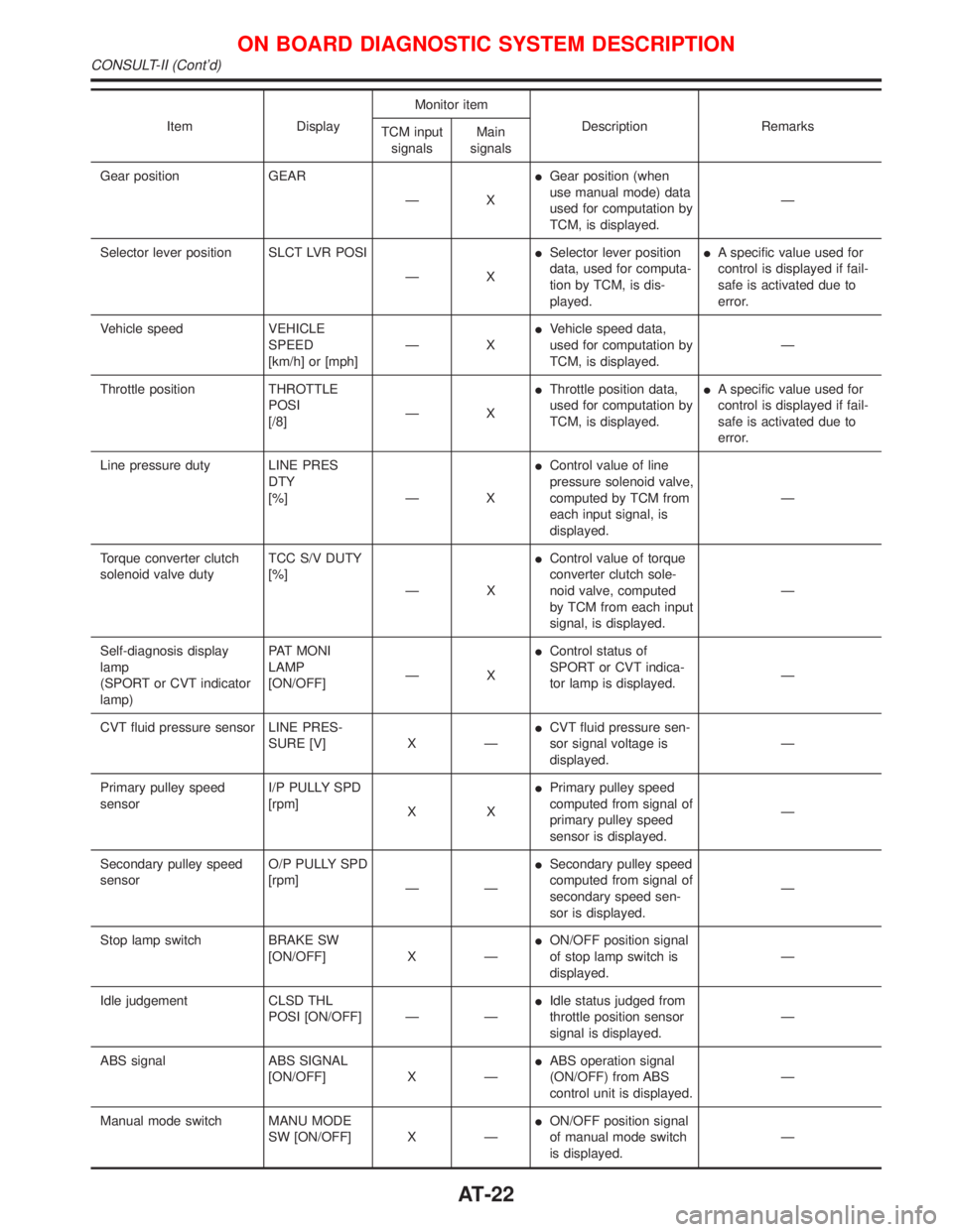
Item DisplayMonitor item
Description Remarks
TCM input
signalsMain
signals
Gear position GEAR
ÐXIGear position (when
use manual mode) data
used for computation by
TCM, is displayed.Ð
Selector lever position SLCT LVR POSI
ÐXISelector lever position
data, used for computa-
tion by TCM, is dis-
played.IA specific value used for
control is displayed if fail-
safe is activated due to
error.
Vehicle speed VEHICLE
SPEED
[km/h] or [mph]ÐXIVehicle speed data,
used for computation by
TCM, is displayed.Ð
Throttle position THROTTLE
POSI
[/8]ÐXIThrottle position data,
used for computation by
TCM, is displayed.IA specific value used for
control is displayed if fail-
safe is activated due to
error.
Line pressure duty LINE PRES
DTY
[%] Ð XIControl value of line
pressure solenoid valve,
computed by TCM from
each input signal, is
displayed.Ð
Torque converter clutch
solenoid valve dutyTCC S/V DUTY
[%]
ÐXIControl value of torque
converter clutch sole-
noid valve, computed
by TCM from each input
signal, is displayed.Ð
Self-diagnosis display
lamp
(SPORT or CVT indicator
lamp)PAT MONI
LAMP
[ON/OFF]ÐXIControl status of
SPORT or CVT indica-
tor lamp is displayed.Ð
CVT fluid pressure sensor LINE PRES-
SURE [V] X ÐICVT fluid pressure sen-
sor signal voltage is
displayed.Ð
Primary pulley speed
sensorI/P PULLY SPD
[rpm]
XXIPrimary pulley speed
computed from signal of
primary pulley speed
sensor is displayed.Ð
Secondary pulley speed
sensorO/P PULLY SPD
[rpm]
ÐÐISecondary pulley speed
computed from signal of
secondary speed sen-
sor is displayed.Ð
Stop lamp switch BRAKE SW
[ON/OFF] X ÐION/OFF position signal
of stop lamp switch is
displayed.Ð
Idle judgement CLSD THL
POSI [ON/OFF] Ð ÐIIdle status judged from
throttle position sensor
signal is displayed.Ð
ABS signal ABS SIGNAL
[ON/OFF] X ÐIABS operation signal
(ON/OFF) from ABS
control unit is displayed.Ð
Manual mode switch MANU MODE
SW [ON/OFF] X ÐION/OFF position signal
of manual mode switch
is displayed.Ð
ON BOARD DIAGNOSTIC SYSTEM DESCRIPTION
CONSULT-II (Cont'd)
AT-22
Page 25 of 2267
![NISSAN PRIMERA 1999 Electronic Repair Manual Item DisplayMonitor item
Description Remarks
TCM input
signalsMain
signals
Non-manual mode switch NON M MODE
SW [ON/OFF] X ÐION/OFF position signal
of non-manual mode
switch is displayed.Ð
Up switch NISSAN PRIMERA 1999 Electronic Repair Manual Item DisplayMonitor item
Description Remarks
TCM input
signalsMain
signals
Non-manual mode switch NON M MODE
SW [ON/OFF] X ÐION/OFF position signal
of non-manual mode
switch is displayed.Ð
Up switch](/manual-img/5/57377/w960_57377-24.png)
Item DisplayMonitor item
Description Remarks
TCM input
signalsMain
signals
Non-manual mode switch NON M MODE
SW [ON/OFF] X ÐION/OFF position signal
of non-manual mode
switch is displayed.Ð
Up switch UP SW
[ON/OFF] X ÐION/OFF position signal
of up switch is dis-
played.Ð
Down switch DOWN SW
[ON/OFF] X ÐION/OFF position signal
of down switch is dis-
played.Ð
Step motor coil A S/M COIL [A]
[ON/OFF]
ÐÐIControl valve of step
motor coil A, computed
by TCM from each input
signal is displayed.Ð
Step motor coil B S/M COIL [B]
[ON/OFF]
ÐÐIControl valve of step
motor coil B, computed
by TCM from each input
signal is displayed.Ð
Step motor coil C S/M COIL [C]
[ON/OFF]
ÐÐIControl valve of step
motor coil C, computed
by TCM from each input
signal is displayed.Ð
Step motor coil D S/M COIL [D]
[ON/OFF]
ÐÐIControl valve of step
motor coil D, computed
by TCM from each input
signal is displayed.Ð
CVT ratio CVT RATIO [Ð]
ÐXIReal CVT ratio operated
TCM is displayed.Ð
Step PLY CONT
STEP [step]ÐXIStep motor position is
displayed.Ð
Line pressure LINE PRES-
SURE [MPa]
ÐXIReal line pressure cal-
culated from line pres-
sure sensor voltage
with TCM is displayed.Ð
Pulley rpm×in 2 T RPM [rpm]
ÐÐITarget primary pulley
speed operated with
TCM is displayed.Ð
CVT ratio 2 T RATIO [Ð]
ÐÐITarget changing the
speed ratio operated
with TCM is displayed.Ð
Step 2 T STEP [step]
ÐÐITarget step motor posi-
tion operated with TCM
is displayed.Ð
X: Applicable
Ð: Not applicable
ON BOARD DIAGNOSTIC SYSTEM DESCRIPTION
CONSULT-II (Cont'd)
AT-23
Page 28 of 2267
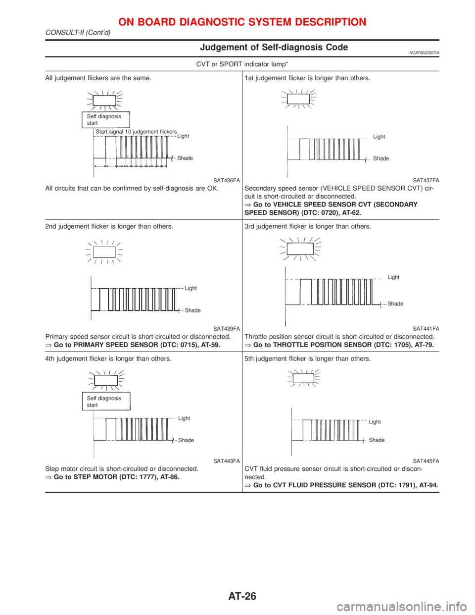
Judgement of Self-diagnosis CodeNCAT0022S0704
CVT or SPORT indicator lamp*
All judgement flickers are the same.
SAT436FA
All circuits that can be confirmed by self-diagnosis are OK.
Self diagnosis
start
Start signal 10 judgement flickers
Light
Shade
1st judgement flicker is longer than others.
SAT437FA Light
Shade
Secondary speed sensor (VEHICLE SPEED SENSOR CVT) cir-
cuit is short-circuited or disconnected.
ÞGo to VEHICLE SPEED SENSOR CVT (SECONDARY
SPEED SENSOR) (DTC: 0720), AT-62.
2nd judgement flicker is longer than others.
SAT439FA
Primary speed sensor circuit is short-circuited or disconnected.
ÞGo to PRIMARY SPEED SENSOR (DTC: 0715), AT-59.
Light
Shade
3rd judgement flicker is longer than others.
SAT441FA
Throttle position sensor circuit is short-circuited or disconnected.
ÞGo to THROTTLE POSITION SENSOR (DTC: 1705), AT-79.
Light
Shade
4th judgement flicker is longer than others.
SAT443FA
Step motor circuit is short-circuited or disconnected.
ÞGo to STEP MOTOR (DTC: 1777), AT-86.
Self diagnosis
start
Light
Shade
5th judgement flicker is longer than others.
SAT445FA Light
Shade
CVT fluid pressure sensor circuit is short-circuited or discon-
nected.
ÞGo to CVT FLUID PRESSURE SENSOR (DTC: 1791), AT-94.
ON BOARD DIAGNOSTIC SYSTEM DESCRIPTION
CONSULT-II (Cont'd)
AT-26
Page 29 of 2267
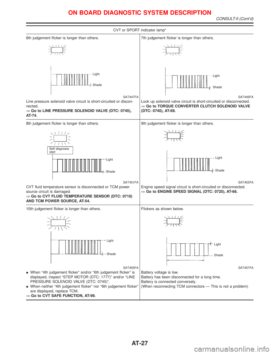
CVT or SPORT indicator lamp*
6th judgement flicker is longer than others.
SAT447FA
Line pressure solenoid valve circuit is short-circuited or discon-
nected.
ÞGo to LINE PRESSURE SOLENOID VALVE (DTC: 0745),
AT-74.
Light
Shade
7th judgement flicker is longer than others.
SAT449FA
Lock up solenoid valve circuit is short-circuited or disconnected.
ÞGo to TORQUE CONVERTER CLUTCH SOLENOID VALVE
(DTC: 0740), AT-69.
Light
Shade
8th judgement flicker is longer than others.
SAT451FA
CVT fluid temperature sensor is disconnected or TCM power
source circuit is damaged.
ÞGo to CVT FLUID TEMPERATURE SENSOR (DTC: 0710)
AND TCM POWER SOURCE, AT-54.
Self diagnosis
start
Light
Shade
9th judgement flicker is longer than others.
SAT453FA
Engine speed signal circuit is short-circuited or disconnected.
ÞGo to ENGINE SPEED SIGNAL (DTC: 0725), AT-66.
Light
Shade
10th judgement flicker is longer than others.
SAT455FA Light
Shade
IWhen ª4th judgement flickerº and/or ª6th judgement flickerº is
displayed, inspect ªSTEP MOTOR (DTC: 1777)º and/or ªLINE
PRESSURE SOLENOID VALVE (DTC: 0745)º.
IWhen neither ª4th judgement flickerº nor ª6th judgement flickerº
are displayed, replace TCM.
ÞGo to CVT SAFE FUNCTION, AT-99.Flickers as shown below.
SAT457FA
Battery voltage is low.
Battery has been disconnected for a long time.
Battery is connected conversely.
(When reconnecting TCM connectors Ð This is not a problem)
Light
Shade
ON BOARD DIAGNOSTIC SYSTEM DESCRIPTION
CONSULT-II (Cont'd)
AT-27