Page 31 of 2267

IntroductionNCAT0023
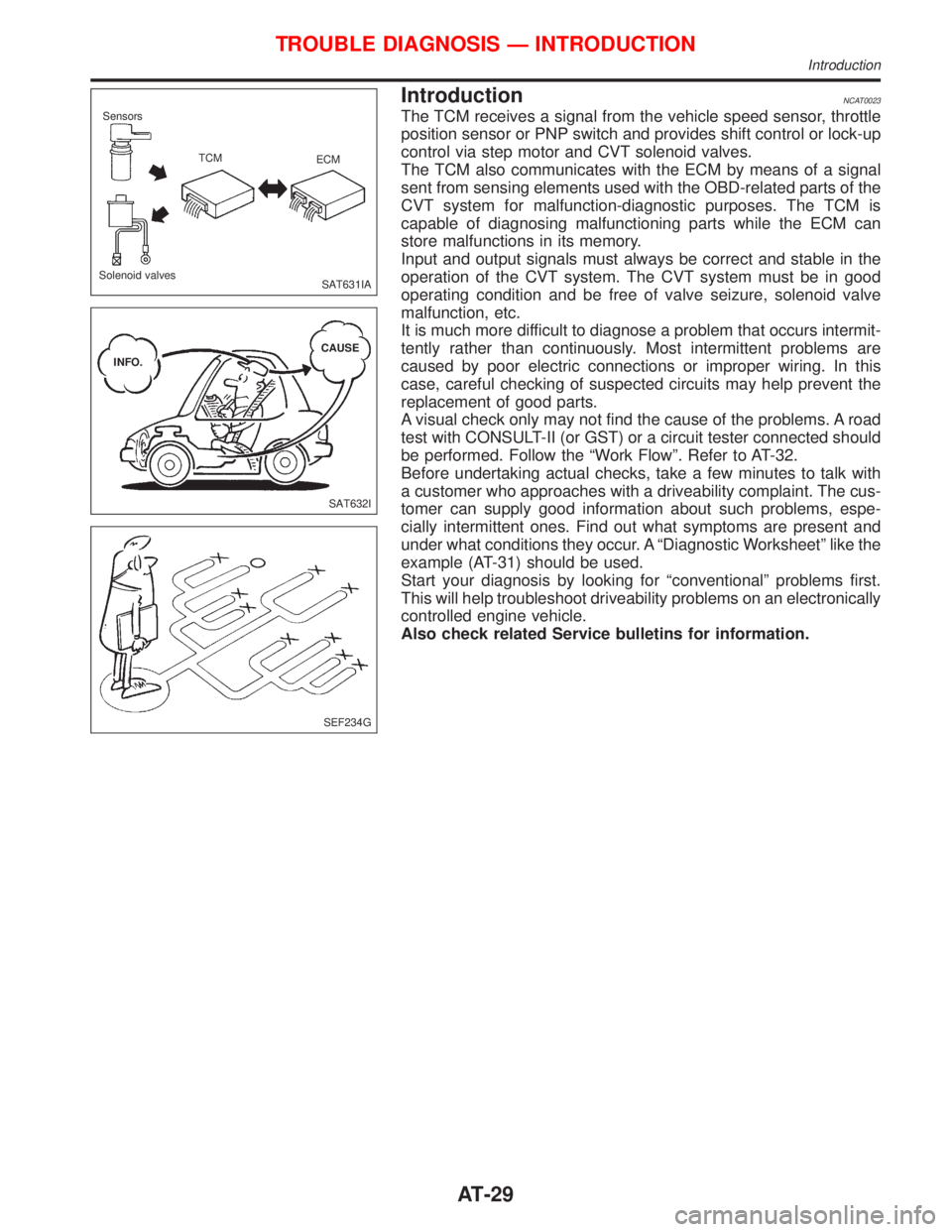
The TCM receives a signal from the vehicle speed sensor, throttle
position sensor or PNP switch and provides shift control or lock-up
control via step motor and CVT solenoid valves.
The TCM also communicates with the ECM by means of a signal
sent from sensing elements used with the OBD-related parts of the
CVT system for malfunction-diagnostic purposes. The TCM is
capable of diagnosing malfunctioning parts while the ECM can
store malfunctions in its memory.
Input and output signals must always be correct and stable in the
operation of the CVT system. The CVT system must be in good
operating condition and be free of valve seizure, solenoid valve
malfunction, etc.
It is much more difficult to diagnose a problem that occurs intermit-
tently rather than continuously. Most intermittent problems are
caused by poor electric connections or improper wiring. In this
case, careful checking of suspected circuits may help prevent the
replacement of good parts.
A visual check only may not find the cause of the problems. A road
test with CONSULT-II (or GST) or a circuit tester connected should
be performed. Follow the ªWork Flowº. Refer to AT-32.
Before undertaking actual checks, take a few minutes to talk with
a customer who approaches with a driveability complaint. The cus-
tomer can supply good information about such problems, espe-
cially intermittent ones. Find out what symptoms are present and
under what conditions they occur. A ªDiagnostic Worksheetº like the
example (AT-31) should be used.
Start your diagnosis by looking for ªconventionalº problems first.
This will help troubleshoot driveability problems on an electronically
controlled engine vehicle.
Also check related Service bulletins for information.
SAT631IA Sensors
TCM
ECM
Solenoid valves
SAT632I INFO.CAUSE
SEF234G
TROUBLE DIAGNOSIS Ð INTRODUCTION
Introduction
AT-29
Page 33 of 2267

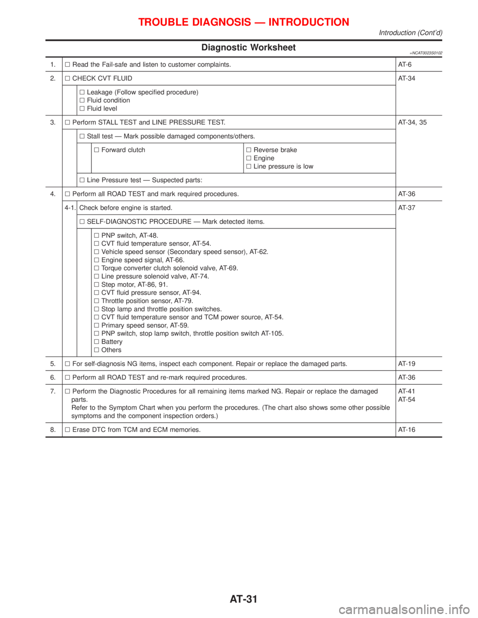
Diagnostic Worksheet=NCAT0023S0102
1.lRead the Fail-safe and listen to customer complaints. AT-6
2.lCHECK CVT FLUIDAT-34
lLeakage (Follow specified procedure)
lFluid condition
lFluid level
3.lPerform STALL TEST and LINE PRESSURE TEST. AT-34, 35
lStall test Ð Mark possible damaged components/others.
lForward clutchlReverse brake
lEngine
lLine pressure is low
lLine Pressure test Ð Suspected parts:
4.lPerform all ROAD TEST and mark required procedures. AT-36
4-1. Check before engine is started.AT-37
lSELF-DIAGNOSTIC PROCEDURE Ð Mark detected items.
lPNP switch, AT-48.
lCVT fluid temperature sensor, AT-54.
lVehicle speed sensor (Secondary speed sensor), AT-62.
lEngine speed signal, AT-66.
lTorque converter clutch solenoid valve, AT-69.
lLine pressure solenoid valve, AT-74.
lStep motor, AT-86, 91.
lCVT fluid pressure sensor, AT-94.
lThrottle position sensor, AT-79.
lStop lamp and throttle position switches.
lCVT fluid temperature sensor and TCM power source, AT-54.
lPrimary speed sensor, AT-59.
lPNP switch, stop lamp switch, throttle position switch AT-105.
lBattery
lOthers
5.lFor self-diagnosis NG items, inspect each component. Repair or replace the damaged parts. AT-19
6.lPerform all ROAD TEST and re-mark required procedures. AT-36
7.lPerform the Diagnostic Procedures for all remaining items marked NG. Repair or replace the damaged
parts.
Refer to the Symptom Chart when you perform the procedures. (The chart also shows some other possible
symptoms and the component inspection orders.)AT-41
AT-54
8.lErase DTC from TCM and ECM memories. AT-16
TROUBLE DIAGNOSIS Ð INTRODUCTION
Introduction (Cont'd)
AT-31
Page 42 of 2267
14. Touch ªPRINTº.
15. Check the monitor data printed out.
16. Continue cruise test part 2 and 3.
Without CONSULT-IINCAT0028S0403IThrottle position sensor can be checked by voltage across
terminals 41 and 42 of TCM.
Refer to ªRoad Testº, AT-36.
SAT610J
SAT417J
TROUBLE DIAGNOSIS Ð BASIC INSPECTION
Road Test (Cont'd)
AT-40
Page 45 of 2267

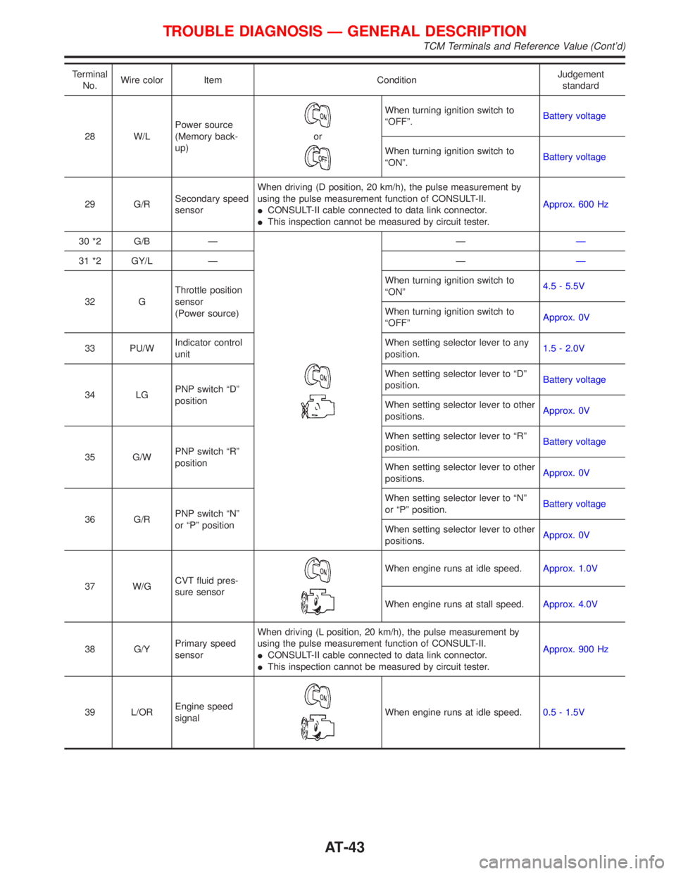
Terminal
No.Wire color Item ConditionJudgement
standard
28 W/LPower source
(Memory back-
up)
or
When turning ignition switch to
ªOFFº.Battery voltage
When turning ignition switch to
ªONº.Battery voltage
29 G/RSecondary speed
sensorWhen driving (D position, 20 km/h), the pulse measurement by
using the pulse measurement function of CONSULT-II.
ICONSULT-II cable connected to data link connector.
IThis inspection cannot be measured by circuit tester.Approx. 600 Hz
30 *2 G/B Ð
ÐÐ
31 *2 GY/L Ð ÐÐ
32 GThrottle position
sensor
(Power source)When turning ignition switch to
ªONº4.5 - 5.5V
When turning ignition switch to
ªOFFºApprox. 0V
33 PU/WIndicator control
unitWhen setting selector lever to any
position.1.5 - 2.0V
34 LGPNP switch ªDº
positionWhen setting selector lever to ªDº
position.Battery voltage
When setting selector lever to other
positions.Approx. 0V
35 G/WPNP switch ªRº
positionWhen setting selector lever to ªRº
position.Battery voltage
When setting selector lever to other
positions.Approx. 0V
36 G/RPNP switch ªNº
or ªPº positionWhen setting selector lever to ªNº
or ªPº position.Battery voltage
When setting selector lever to other
positions.Approx. 0V
37 W/GCVT fluid pres-
sure sensor
When engine runs at idle speed.Approx. 1.0V
When engine runs at stall speed.Approx. 4.0V
38 G/YPrimary speed
sensorWhen driving (L position, 20 km/h), the pulse measurement by
using the pulse measurement function of CONSULT-II.
ICONSULT-II cable connected to data link connector.
IThis inspection cannot be measured by circuit tester.Approx. 900 Hz
39 L/OREngine speed
signal
When engine runs at idle speed.0.5 - 1.5V
TROUBLE DIAGNOSIS Ð GENERAL DESCRIPTION
TCM Terminals and Reference Value (Cont'd)
AT-43
Page 46 of 2267
Terminal
No.Wire color Item ConditionJudgement
standard
41 GYThrottle position
sensor
When depressing accelerator pedal
slowly after warming up engine.
(Voltage rises gradually in response
to throttle position.)Fully-closed
throttle:
Approximately
0.3V
Fully-open
throttle:
Approximately 3V
42 B/WThrottle position
sensor
(Ground)ÐÐ
45 R/G Stop lamp switchWhen depressing brake pedalBattery voltage
When releasing brake pedalApprox. 0V
46 P/LCVT fluid pres-
sure sensor
(Power source)Ð4.5 - 5.5V
47 Y/PUCVT fluid tem-
perature sensorWhen CVT fluid temperature is
20ÉC (68ÉF).Approximately
1.5V
When CVT fluid temperature is
80ÉC (176ÉF).Approximately
0.5V
48 B Ground ÐÐ
*1: This terminal is connected to the ECM.
*2: These terminals are connected to the Data link connector for CONSULT-II.
TROUBLE DIAGNOSIS Ð GENERAL DESCRIPTION
TCM Terminals and Reference Value (Cont'd)
AT-44
Page 56 of 2267

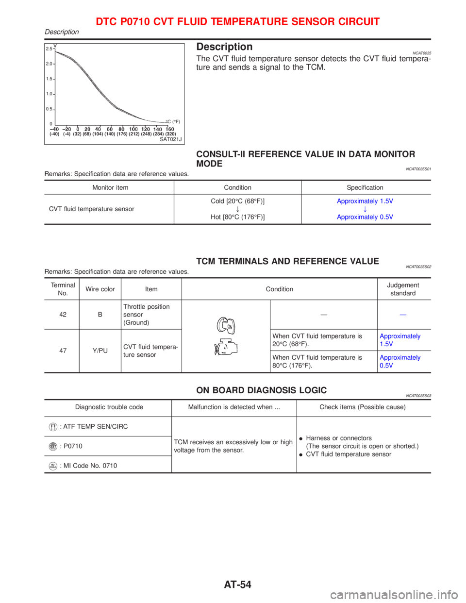
DescriptionNCAT0035The CVT fluid temperature sensor detects the CVT fluid tempera-
ture and sends a signal to the TCM.
CONSULT-II REFERENCE VALUE IN DATA MONITOR
MODE
NCAT0035S01Remarks: Specification data are reference values.
Monitor item Condition Specification
CVT fluid temperature sensorCold [20ÉC (68ÉF)]
"
Hot [80ÉC (176ÉF)]Approximately 1.5V
"
Approximately 0.5V
TCM TERMINALS AND REFERENCE VALUENCAT0035S02Remarks: Specification data are reference values.
Terminal
No.Wire color Item ConditionJudgement
standard
42 BThrottle position
sensor
(Ground)
ÐÐ
47 Y/PUCVT fluid tempera-
ture sensorWhen CVT fluid temperature is
20ÉC (68ÉF).Approximately
1.5V
When CVT fluid temperature is
80ÉC (176ÉF).Approximately
0.5V
ON BOARD DIAGNOSIS LOGICNCAT0035S03
Diagnostic trouble code Malfunction is detected when ... Check items (Possible cause)
: ATF TEMP SEN/CIRC
TCM receives an excessively low or high
voltage from the sensor.IHarness or connectors
(The sensor circuit is open or shorted.)
ICVT fluid temperature sensor
: P0710
: MI Code No. 0710
SAT021J
2.5
2.0
1.5
1.0
0.5
0
(-40) (-4) (32) (68) (104) (140) (176) (212) (248) (284) (320)ÉC (ÉF)
DTC P0710 CVT FLUID TEMPERATURE SENSOR CIRCUIT
Description
AT-54
Page 57 of 2267
DIAGNOSTIC TROUBLE CODE (DTC) CONFIRMATION
PROCEDURE
NCAT0035S04CAUTION:
Always drive vehicle at a safe speed.
NOTE:
If ªDIAGNOSTIC TROUBLE CODE CONFIRMATION PROCE-
DUREº has been previously conducted, always turn ignition
switch ªOFFº and wait at least 5 seconds before conducting
the next test.
After the repair, perform the following procedure to confirm the
malfunction is eliminated.
With CONSULT-II
1) Turn ignition switch ªONº and select ªDATA MONITORº mode
for ªENGINEº with CONSULT-II.
2) Start engine and maintain the following conditions for at least
10 minutes (Total). (It is not necessary to maintain continu-
ously.)
ENG SPEED: 450 rpm or more
VHCL SPEED SE: 10 km/h (6 MPH) or more
THRTL POS SEN: More than 1.3 V
Selector lever: D position
If the check result is NG, go to ªDiagnostic Procedureº, AT-57.
With GST
Follow the procedure ªWith CONSULT-IIº.
SAT651J
SAT654J
DTC P0710 CVT FLUID TEMPERATURE SENSOR CIRCUIT
Description (Cont'd)
AT-55
Page 58 of 2267
Wiring Diagram Ð AT Ð FTSNCAT0200
YAT203
CONTROL VALVE
(CVT FLUID
TEMPERATURE
SENSOR)
: Detectable line for DTC
: Non-detectable line for DTC
TCM
(TRANSMISSION
CONTROL MODULE)ECM
DTC P0710 CVT FLUID TEMPERATURE SENSOR CIRCUIT
Wiring Diagram Ð AT Ð FTS
AT-56