Page 464 of 666
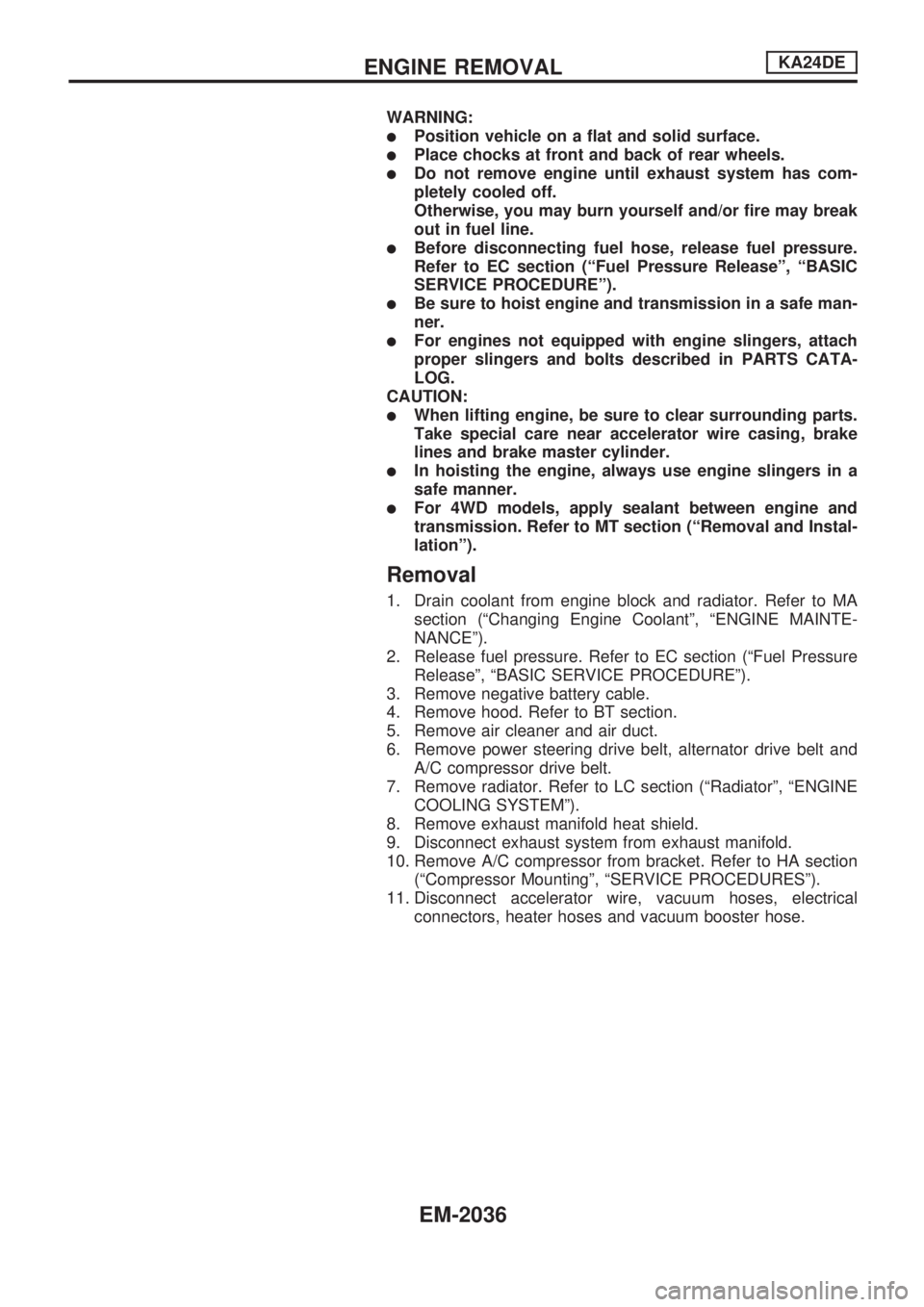
WARNING:
lPosition vehicle on a flat and solid surface.
lPlace chocks at front and back of rear wheels.
lDo not remove engine until exhaust system has com-
pletely cooled off.
Otherwise, you may burn yourself and/or fire may break
out in fuel line.
lBefore disconnecting fuel hose, release fuel pressure.
Refer to EC section (ªFuel Pressure Releaseº, ªBASIC
SERVICE PROCEDUREº).
lBe sure to hoist engine and transmission in a safe man-
ner.
lFor engines not equipped with engine slingers, attach
proper slingers and bolts described in PARTS CATA-
LOG.
CAUTION:
lWhen lifting engine, be sure to clear surrounding parts.
Take special care near accelerator wire casing, brake
lines and brake master cylinder.
lIn hoisting the engine, always use engine slingers in a
safe manner.
lFor 4WD models, apply sealant between engine and
transmission. Refer to MT section (ªRemoval and Instal-
lationº).
Removal
1. Drain coolant from engine block and radiator. Refer to MA
section (ªChanging Engine Coolantº, ªENGINE MAINTE-
NANCEº).
2. Release fuel pressure. Refer to EC section (ªFuel Pressure
Releaseº, ªBASIC SERVICE PROCEDUREº).
3. Remove negative battery cable.
4. Remove hood. Refer to BT section.
5. Remove air cleaner and air duct.
6. Remove power steering drive belt, alternator drive belt and
A/C compressor drive belt.
7. Remove radiator. Refer to LC section (ªRadiatorº, ªENGINE
COOLING SYSTEMº).
8. Remove exhaust manifold heat shield.
9. Disconnect exhaust system from exhaust manifold.
10. Remove A/C compressor from bracket. Refer to HA section
(ªCompressor Mountingº, ªSERVICE PROCEDURESº).
11. Disconnect accelerator wire, vacuum hoses, electrical
connectors, heater hoses and vacuum booster hose.
ENGINE REMOVALKA24DE
EM-2036
Page 496 of 666
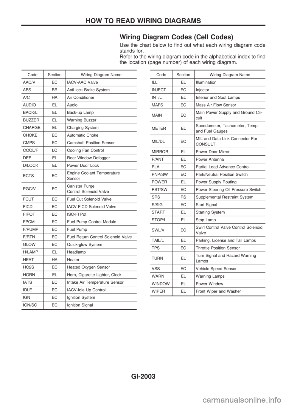
Wiring Diagram Codes (Cell Codes)
Use the chart below to find out what each wiring diagram code
stands for.
Refer to the wiring diagram code in the alphabetical index to find
the location (page number) of each wiring diagram.
Code Section Wiring Diagram Name
AAC/V EC IACV-AAC Valve
ABS BR Anti-lock Brake System
A/C HA Air Conditioner
AUDIO EL Audio
BACK/L EL Back-up Lamp
BUZZER EL Warning Buzzer
CHARGE EL Charging System
CHOKE EC Automatic Choke
CMPS EC Camshaft Position Sensor
COOL/F LC Cooling Fan Control
DEF EL Rear Window Defogger
D/LOCK EL Power Door Lock
ECTS ECEngine Coolant Temperature
Sensor
PGC/V ECCanister Purge
Control Solenoid Valve
FCUT EC Fuel Cut Solenoid Valve
FICD EC IACV-FICD Solenoid Valve
FIPOT EC ISC-FI Pot
FPCM EC Fuel Pump Control Module
F/PUMP EC Fuel Pump
F/RTN EC Fuel Return Control Solenoid Valve
GLOW EC Quick-glow System
H/LAMP EL Headlamp
HEAT HA Heater
HO2S EC Heated Oxygen Sensor
HORN EL Horn, Cigarette Lighter, Clock
IATS EC Intake Air Temperature Sensor
IDLE EC IACV-Idle Up Control
IGN EC Ignition System
IGN/SG EC Ignition SignalCode Section Wiring Diagram Name
ILL EL Illumination
INJECT EC Injector
INT/L EL Interior and Spot Lamps
MAFS EC Mass Air Flow Sensor
MAIN ECMain Power Supply and Ground Cir-
cuit
METER ELSpeedometer, Tachometer, Temp.
and Fuel Gauges
MIL/DL ECMIL and Data Link Connector For
CONSULT
MIRROR EL Power Door Mirror
P/ANT EL Power Antenna
PLA EC Partial Load Advance Control
PNP/SW EC Park/Neutral Position Switch
POWER EL Power Supply Routing
PST/SW EC Power Steering Oil Pressure Switch
SRS RS Supplemental Restraint System
S/SIG EC Start Signal
START EL Starting System
STOP/L EL Stop Lamp
SWL/V ECSwirl Control Valve Control Solenoid
Valve
TAIL/L EL Parking, License and Tail Lamps
TPS EC Throttle Position Sensor
TURN ELTurn Signal and Hazard Warning
Lamps
VSS EC Vehicle Speed Sensor
WARN EL Warning Lamps
WINDOW EL Power Window
WIPER EL Front Wiper and Washer
HOW TO READ WIRING DIAGRAMS
GI-2003
Page 501 of 666

\
HEATER&
AIR CONDITIONER
SECTION
HA
MODIFICATION NOTICE:
lWiring Diagrams for manual A/C have been changed.
lAuto A/C has been added to RHD models for Europe.
lAuto A/C of LHD models for Europe have been changed.
CONTENTS
MANUAL AND AUTO
PRECAUTIONS AND PREPARATION ............... 2002
Supplemental Restraint System (SRS) ²AIR
BAG ²and ²SEAT BELT PRE-TENSIONER ².. 2002
MANUAL
TROUBLE DIAGNOSES ..................................... 2003
Wiring Diagram - HEATER -............................ 2003
Circuit Diagram - Air Conditioner..................... 2004
Wiring Diagram - A/C, M -/Except for KA
Engine Models ................................................. 2005
Wiring Diagram - A/C, M -/KA Engine LHD
Models.............................................................. 2008
Wiring Diagram - A/C, M -/KA Engine RHD
Models.............................................................. 2011
Magnet Clutch .................................................. 2014
AUTO
DESCRIPTION..................................................... 2023
Introduction ...................................................... 2023
Features ........................................................... 2023
Overview of Control System ............................ 2024
Control Operation............................................. 2024
TROUBLE DIAGNOSES ..................................... 2026 Component Location ........................................ 2026
Circuit Diagram ................................................ 2027
Wiring Diagram - A/C, A -................................ 2028
Auto Amp. Terminals and Reference Value .... 2032
Self-diagnosis................................................... 2034
How to Perform Trouble Diagnoses for Quick
and Accurate Repair ........................................ 2040
Operational Check ........................................... 2041
A/C System ...................................................... 2045
Mode Door Motor ............................................. 2047
Air Mix Door Motor........................................... 2052
Intake Door Motor ............................................ 2058
Blower Motor .................................................... 2062
Magnet Clutch .................................................. 2068
Insufficient Cooling........................................... 2075
Insufficient Heating .......................................... 2076
Noise ................................................................ 2077
Self-diagnosis................................................... 2078
Memory Function ............................................. 2079
Ambient Sensor ............................................... 2080
In-vehicle Sensor ............................................. 2082
Aspirator Motor ................................................ 2084
Sunload Sensor ............................................... 2084
Intake Sensor ................................................... 2087
When you read wiring diagrams:
+
Read GI section, ªHOW TO READ WIRING DIAGRAMSº.
+ See EL section, ªPOWER SUPPLY ROUTINGº for power distribution circuit.
When you perform trouble diagnoses, read GI section, ªHOW TO FOLLOW FLOW
CHART IN TROUBLE DIAGNOSESº and ªHOW TO PERFORM EFFICIENT DIAGNOSIS
FOR AN ELECTRICAL INCIDENTº.
HA
Page 503 of 666
Wiring Diagram Ð HEATER Ð
EXCEPT FOR AUSTRALIA
HHA176
TROUBLE DIAGNOSESMANUAL
HA-2003
Page 548 of 666
SYSTEM DESCRIPTION
Component parts
Mode door control system components are:
1) Auto amplifier
2) Mode door motor
3) In-vehicle sensor4) Ambient sensor
5) Sunload sensor
6) Intake sensor
System operation
The auto amplifier computes the air outlet conditions according to the ambient temperature and the in-ve-
hicle temperature. The computed outlet conditions are then corrected for sunload to determine air outlet
through which air is discharged into the passenger compartment.
Mode door control specification
COMPONENT DESCRIPTION
The mode door motor is attached to the heater unit. It rotates so
that air is discharged from the outlet set by the auto amplifier.
Motor rotation is conveyed to a link which activates the mode
door.
RHA471H
RHA384H
RHA472H
TROUBLE DIAGNOSESAUTO
Mode Door Motor (Cont'd)
HA-2048
Page 551 of 666
COMPONENT INSPECTION
Mode door motor
Terminal No.
Mode door operation Direction of side link rotation
V8V7
Å@VENT®DEF Counterclockwise
þ þ STOP STOP
@
ÅDEF®VENT Clockwise
CONTROL LINKAGE ADJUSTMENT
Mode door
1. Install mode door motor on heater unit and connect it to main
harness.
2. Set up code No.
in Self-diagnosis STEP 4. Refer to
HA-2038.
3. Move side link by hand and hold mode door in DEF mode.
4. Make sure mode door operates properly when changing from
code No.
toby pushing DEF switch.
VENT B/L B/L FOOT D/F DEF
RHA480H
RHA481H
RHA472H
TROUBLE DIAGNOSESAUTO
Mode Door Motor (Cont'd)
HA-2051
Page 554 of 666
COMPONENT DESCRIPTION
The air mix door motor is attached to the heater unit. It rotates
so that the air mix door is opened or closed to a position set by
the auto amplifier. Motor rotation is then conveyed through a
shaft and the air mix door position is then fed back to the auto
amplifier by PBR built-in air mix door motor.
RHA483H
TROUBLE DIAGNOSESAUTO
Air Mix Door Motor (Cont'd)
HA-2054
Page 557 of 666
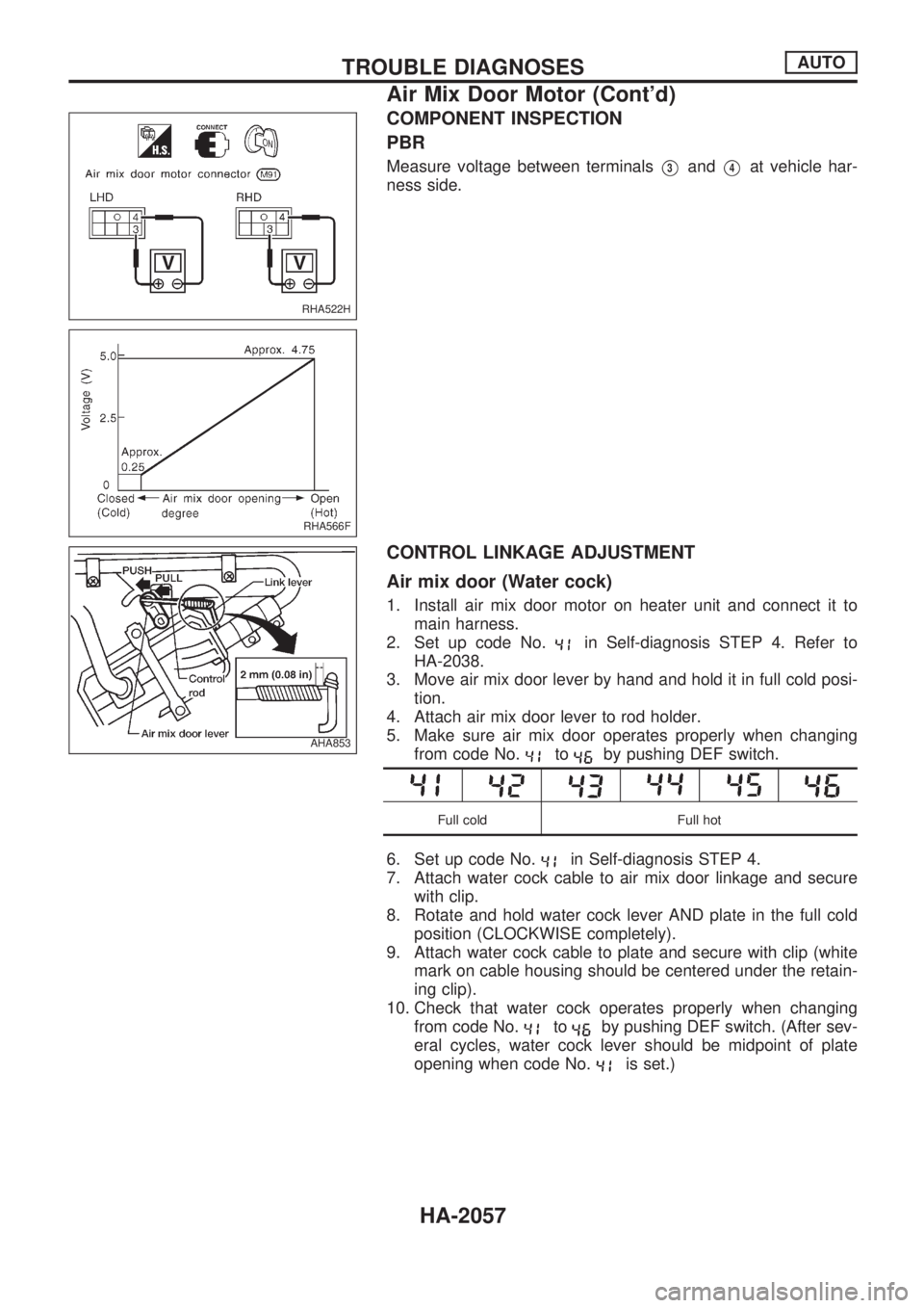
COMPONENT INSPECTION
PBR
Measure voltage between terminalsV3andV4at vehicle har-
ness side.
CONTROL LINKAGE ADJUSTMENT
Air mix door (Water cock)
1. Install air mix door motor on heater unit and connect it to
main harness.
2. Set up code No.
in Self-diagnosis STEP 4. Refer to
HA-2038.
3. Move air mix door lever by hand and hold it in full cold posi-
tion.
4. Attach air mix door lever to rod holder.
5. Make sure air mix door operates properly when changing
from code No.
toby pushing DEF switch.
Full cold Full hot
6. Set up code No.in Self-diagnosis STEP 4.
7. Attach water cock cable to air mix door linkage and secure
with clip.
8. Rotate and hold water cock lever AND plate in the full cold
position (CLOCKWISE completely).
9. Attach water cock cable to plate and secure with clip (white
mark on cable housing should be centered under the retain-
ing clip).
10. Check that water cock operates properly when changing
from code No.
toby pushing DEF switch. (After sev-
eral cycles, water cock lever should be midpoint of plate
opening when code No.
is set.)
RHA522H
RHA566F
AHA853
TROUBLE DIAGNOSESAUTO
Air Mix Door Motor (Cont'd)
HA-2057


