1999 NISSAN PICK-UP check engine
[x] Cancel search: check enginePage 80 of 666
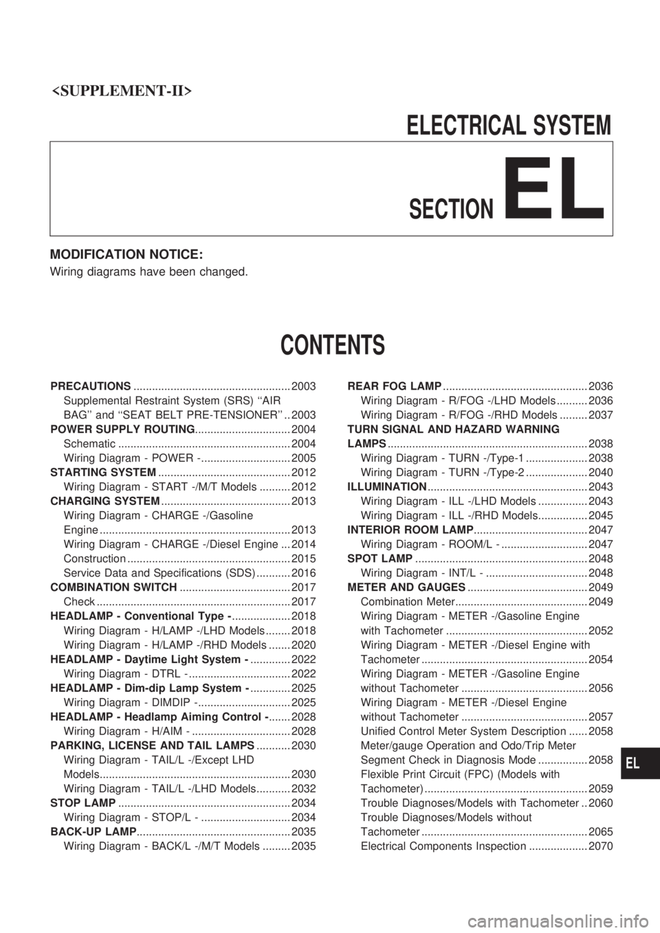
ELECTRICALSYSTEM
SECTION
EL
MODIFICATION NOTICE:
Wiring diagrams have been changed.
CONTENTS
PRECAUTIONS ................................................... 2003
Supplemental Restraint System (SRS) ``AIR
BAG'' and ``SEAT BELT PRE-TENSIONER'' .. 2003
POWER SUPPLY ROUTING ............................... 2004
Schematic ........................................................ 2004
Wiring Diagram - POWER -............................. 2005
STARTING SYSTEM ........................................... 2012
Wiring Diagram - START -/M/T Models .......... 2012
CHARGING SYSTEM .......................................... 2013
Wiring Diagram - CHARGE -/Gasoline
Engine .............................................................. 2013
Wiring Diagram - CHARGE -/Diesel Engine ... 2014
Construction ..................................................... 2015
Service Data and Specifications (SDS) ........... 2016
COMBINATION SWITCH .................................... 2017
Check ............................................................... 2017
HEADLAMP - Conventional Type - ................... 2018
Wiring Diagram - H/LAMP -/LHD Models ........ 2018
Wiring Diagram - H/LAMP -/RHD Models ....... 2020
HEADLAMP - Daytime Light System - ............. 2022
Wiring Diagram - DTRL - ................................. 2022
HEADLAMP - Dim-dip Lamp System - ............. 2025
Wiring Diagram - DIMDIP -.............................. 2025
HEADLAMP - Headlamp Aiming Control - ....... 2028
Wiring Diagram - H/AIM - ................................ 2028
PARKING, LICENSE AND TAIL LAMPS ........... 2030
Wiring Diagram - TAIL/L -/Except LHD
Models.............................................................. 2030
Wiring Diagram - TAIL/L -/LHD Models........... 2032
STOP LAMP ........................................................ 2034
Wiring Diagram - STOP/L - ............................. 2034
BACK-UP LAMP .................................................. 2035
Wiring Diagram - BACK/L -/M/T Models ......... 2035 REAR FOG LAMP
............................................... 2036
Wiring Diagram - R/FOG -/LHD Models .......... 2036
Wiring Diagram - R/FOG -/RHD Models ......... 2037
TURN SIGNAL AND HAZARD WARNING
LAMPS ................................................................. 2038
Wiring Diagram - TURN -/Type-1 .................... 2038
Wiring Diagram - TURN -/Type-2 .................... 2040
ILLUMINATION .................................................... 2043
Wiring Diagram - ILL -/LHD Models ................ 2043
Wiring Diagram - ILL -/RHD Models................ 2045
INTERIOR ROOM LAMP ..................................... 2047
Wiring Diagram - ROOM/L - ............................ 2047
SPOT LAMP ........................................................ 2048
Wiring Diagram - INT/L - ................................. 2048
METER AND GAUGES ....................................... 2049
Combination Meter........................................... 2049
Wiring Diagram - METER -/Gasoline Engine
with Tachometer .............................................. 2052
Wiring Diagram - METER -/Diesel Engine with
Tachometer ...................................................... 2054
Wiring Diagram - METER -/Gasoline Engine
without Tachometer ......................................... 2056
Wiring Diagram - METER -/Diesel Engine
without Tachometer ......................................... 2057
Unified Control Meter System Description ...... 2058
Meter/gauge Operation and Odo/Trip Meter
Segment Check in Diagnosis Mode ................ 2058
Flexible Print Circuit (FPC) (Models with
Tachometer) ..................................................... 2059
Trouble Diagnoses/Models with Tachometer .. 2060
Trouble Diagnoses/Models without
Tachometer ...................................................... 2065
Electrical Components Inspection ................... 2070
EL
Page 140 of 666
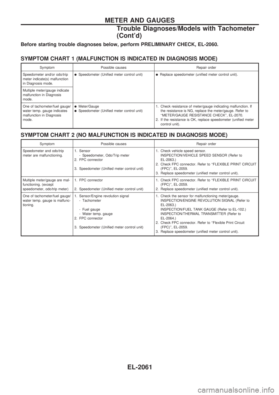
Before starting trouble diagnoses below, perform PRELIMINARY CHECK, EL-2060.
SYMPTOM CHART 1 (MALFUNCTION IS INDICATED IN DIAGNOSIS MODE)
Symptom Possible causes Repair order
Speedometer and/or odo/trip
meter indicate(s) malfunction
in Diagnosis mode.
lSpeedometer (Unified meter control unit)lReplace speedometer (unified meter control unit).
Multiple meter/gauge indicate
malfunction in Diagnosis
mode.
One of tachometer/fuel gauge/
water temp. gauge indicates
malfunction in Diagnosis
mode.
lMeter/GaugelSpeedometer (Unified meter control unit)1. Check resistance of meter/gauge indicating malfunction. If
the resistance is NG, replace the meter/gauge. Refer to
``METER/GAUGE RESISTANCE CHECK'', EL-2070.
2. If the resistance is OK, replace speedometer (unified meter
control unit).
SYMPTOM CHART 2 (NO MALFUNCTION IS INDICATED IN DIAGNOSIS MODE)
Symptom Possible causes Repair order
Speedometer and odo/trip
meter are malfunctioning.1. Sensor
- Speedometer, Odo/Trip meter
2. FPC connector
3. Speedometer (Unified meter control unit)1. Check vehicle speed sensor.
INSPECTION/VEHICLE SPEED SENSOR (Refer to
EL-2063.)
2. Check FPC connector. Refer to ``FLEXIBLE PRINT CIRCUIT
(FPC)'', EL-2059.
3. Replace speedometer (unified meter control unit).
Multiple meter/gauge are mal-
functioning. (except
speedometer, odo/trip meter)1. FPC connector
2. Speedometer (Unified meter control unit)1. Check FPC connector. Refer to ``FLEXIBLE PRINT CIRCUIT
(FPC)'', EL-2059.
2. Replace speedometer (unified meter control unit).
One of tachometer/fuel gauge/
water temp. gauge is malfunc-
tioning.1. Sensor/Engine revolution signal
- Tachometer
- Fuel gauge
- Water temp. gauge
2. FPC connector
3. Speedometer (Unified meter control unit)1. Check the sensor for malfunctioning meter/gauge.
INSPECTION/ENGINE REVOLUTION SIGNAL (Refer to
EL-2063.)
INSPECTION/FUEL TANK GAUGE (Refer to EL-102.)
INSPECTION/THERMAL TRANSMITTER (Refer to
EL-2064.)
2. Check FPC connector. Refer to ``Flexible Print Circuit
(FPC)'', EL-2059.
3. Replace speedometer (unified meter control unit).
METER AND GAUGES
Trouble Diagnoses/Models with Tachometer
(Cont'd)
EL-2061
Page 142 of 666
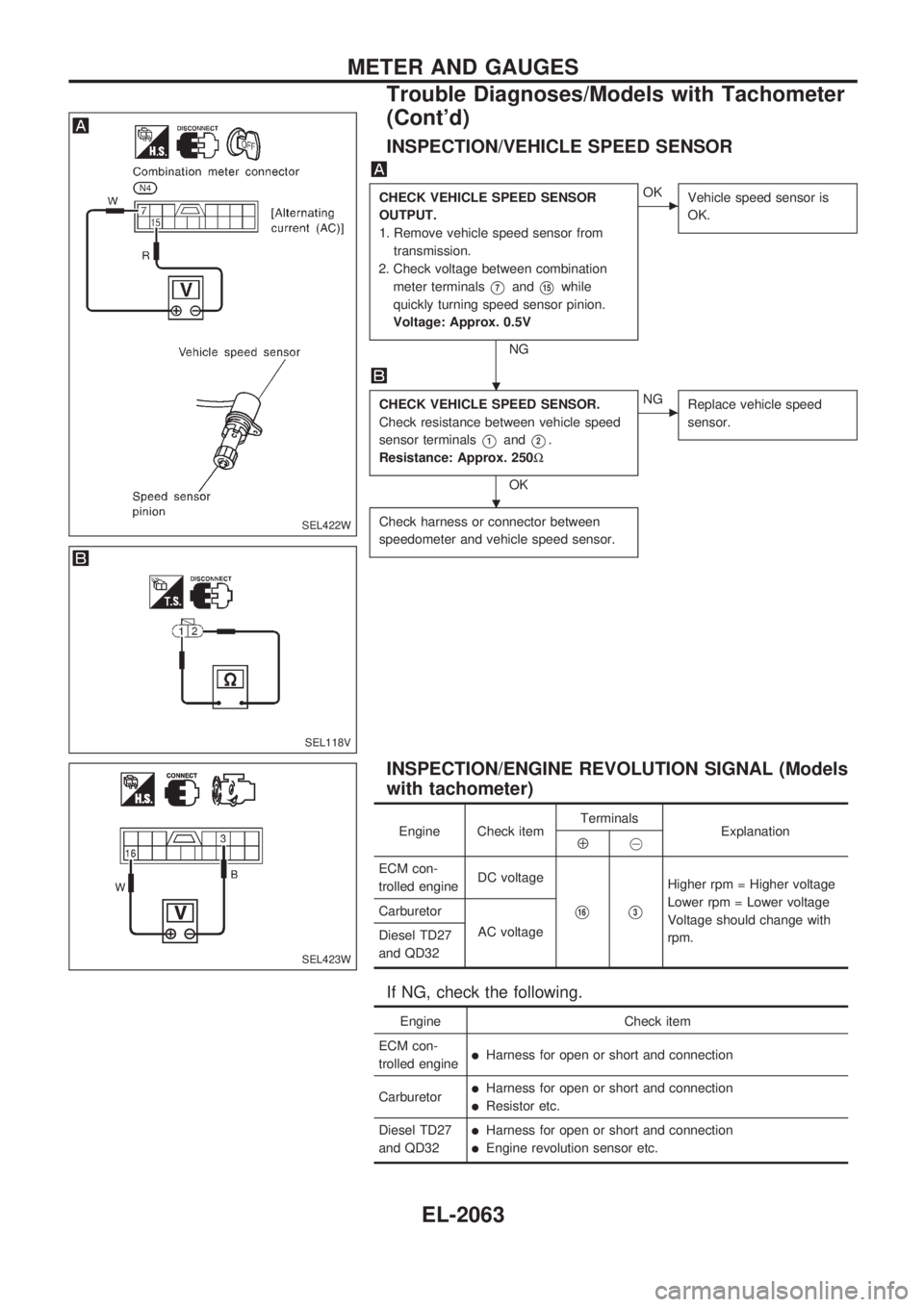
INSPECTION/VEHICLE SPEED SENSOR
CHECK VEHICLE SPEED SENSOR
OUTPUT.
1. Remove vehicle speed sensor from
transmission.
2. Check voltage between combination
meter terminals
V7andV15while
quickly turning speed sensor pinion.
Voltage: Approx. 0.5V
NG
cOK
Vehicle speed sensor is
OK.
CHECK VEHICLE SPEED SENSOR.
Check resistance between vehicle speed
sensor terminals
V1andV2.
Resistance: Approx. 250W
OK
cNG
Replace vehicle speed
sensor.
Check harness or connector between
speedometer and vehicle speed sensor.
INSPECTION/ENGINE REVOLUTION SIGNAL (Models
with tachometer)
Engine Check itemTerminals
ExplanationÅ@
ECM con-
trolled engineDC voltage
V16V3
Higher rpm = Higher voltage
Lower rpm = Lower voltage
Voltage should change with
rpm. Carburetor
AC voltage
Diesel TD27
and QD32
If NG, check the following.
Engine Check item
ECM con-
trolled engine
lHarness for open or short and connection
Carburetor
lHarness for open or short and connection
lResistor etc.
Diesel TD27
and QD32
lHarness for open or short and connection
lEngine revolution sensor etc.
SEL422W
SEL118V
SEL423W
.
.
METER AND GAUGES
Trouble Diagnoses/Models with Tachometer
(Cont'd)
EL-2063
Page 252 of 666
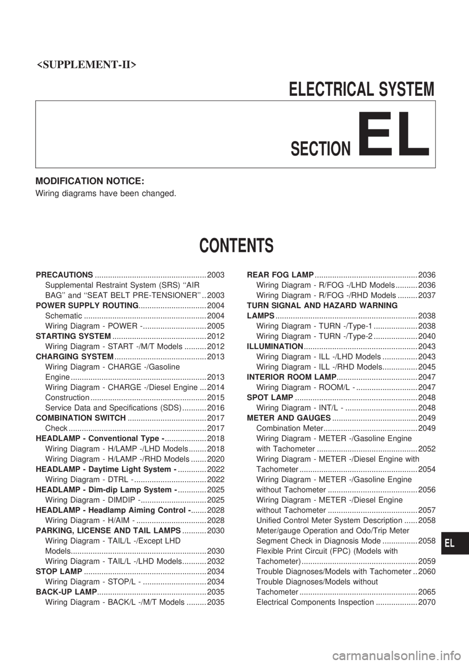
ELECTRICALSYSTEM
SECTION
EL
MODIFICATION NOTICE:
Wiring diagrams have been changed.
CONTENTS
PRECAUTIONS ................................................... 2003
Supplemental Restraint System (SRS) ``AIR
BAG'' and ``SEAT BELT PRE-TENSIONER'' .. 2003
POWER SUPPLY ROUTING ............................... 2004
Schematic ........................................................ 2004
Wiring Diagram - POWER -............................. 2005
STARTING SYSTEM ........................................... 2012
Wiring Diagram - START -/M/T Models .......... 2012
CHARGING SYSTEM .......................................... 2013
Wiring Diagram - CHARGE -/Gasoline
Engine .............................................................. 2013
Wiring Diagram - CHARGE -/Diesel Engine ... 2014
Construction ..................................................... 2015
Service Data and Specifications (SDS) ........... 2016
COMBINATION SWITCH .................................... 2017
Check ............................................................... 2017
HEADLAMP - Conventional Type - ................... 2018
Wiring Diagram - H/LAMP -/LHD Models ........ 2018
Wiring Diagram - H/LAMP -/RHD Models ....... 2020
HEADLAMP - Daytime Light System - ............. 2022
Wiring Diagram - DTRL - ................................. 2022
HEADLAMP - Dim-dip Lamp System - ............. 2025
Wiring Diagram - DIMDIP -.............................. 2025
HEADLAMP - Headlamp Aiming Control - ....... 2028
Wiring Diagram - H/AIM - ................................ 2028
PARKING, LICENSE AND TAIL LAMPS ........... 2030
Wiring Diagram - TAIL/L -/Except LHD
Models.............................................................. 2030
Wiring Diagram - TAIL/L -/LHD Models........... 2032
STOP LAMP ........................................................ 2034
Wiring Diagram - STOP/L - ............................. 2034
BACK-UP LAMP .................................................. 2035
Wiring Diagram - BACK/L -/M/T Models ......... 2035 REAR FOG LAMP
............................................... 2036
Wiring Diagram - R/FOG -/LHD Models .......... 2036
Wiring Diagram - R/FOG -/RHD Models ......... 2037
TURN SIGNAL AND HAZARD WARNING
LAMPS ................................................................. 2038
Wiring Diagram - TURN -/Type-1 .................... 2038
Wiring Diagram - TURN -/Type-2 .................... 2040
ILLUMINATION .................................................... 2043
Wiring Diagram - ILL -/LHD Models ................ 2043
Wiring Diagram - ILL -/RHD Models................ 2045
INTERIOR ROOM LAMP ..................................... 2047
Wiring Diagram - ROOM/L - ............................ 2047
SPOT LAMP ........................................................ 2048
Wiring Diagram - INT/L - ................................. 2048
METER AND GAUGES ....................................... 2049
Combination Meter........................................... 2049
Wiring Diagram - METER -/Gasoline Engine
with Tachometer .............................................. 2052
Wiring Diagram - METER -/Diesel Engine with
Tachometer ...................................................... 2054
Wiring Diagram - METER -/Gasoline Engine
without Tachometer ......................................... 2056
Wiring Diagram - METER -/Diesel Engine
without Tachometer ......................................... 2057
Unified Control Meter System Description ...... 2058
Meter/gauge Operation and Odo/Trip Meter
Segment Check in Diagnosis Mode ................ 2058
Flexible Print Circuit (FPC) (Models with
Tachometer) ..................................................... 2059
Trouble Diagnoses/Models with Tachometer .. 2060
Trouble Diagnoses/Models without
Tachometer ...................................................... 2065
Electrical Components Inspection ................... 2070
EL
Page 312 of 666
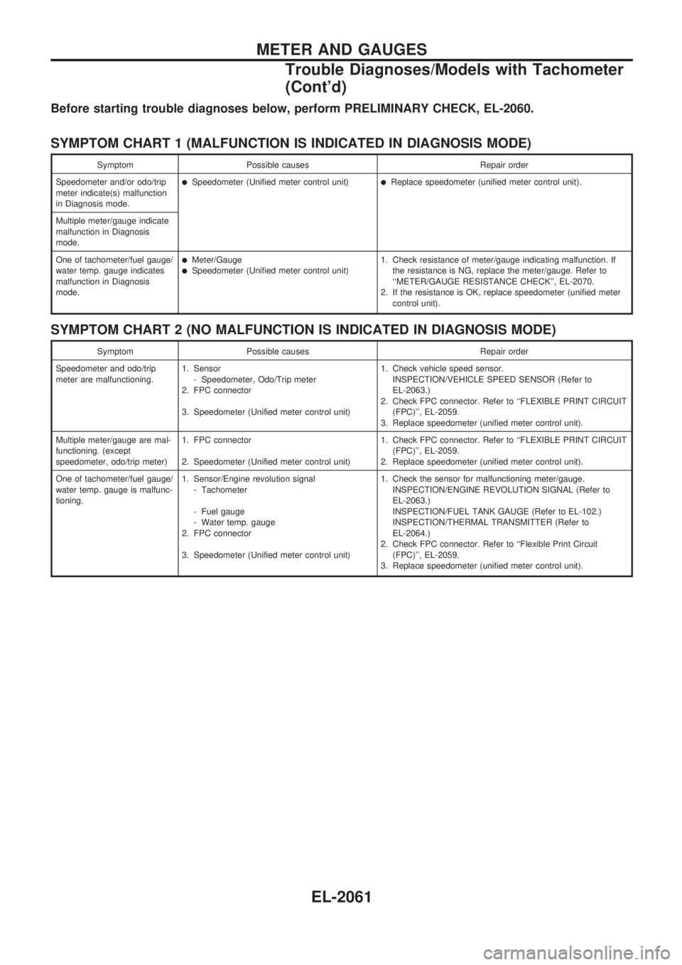
Before starting trouble diagnoses below, perform PRELIMINARY CHECK, EL-2060.
SYMPTOM CHART 1 (MALFUNCTION IS INDICATED IN DIAGNOSIS MODE)
Symptom Possible causes Repair order
Speedometer and/or odo/trip
meter indicate(s) malfunction
in Diagnosis mode.
lSpeedometer (Unified meter control unit)lReplace speedometer (unified meter control unit).
Multiple meter/gauge indicate
malfunction in Diagnosis
mode.
One of tachometer/fuel gauge/
water temp. gauge indicates
malfunction in Diagnosis
mode.
lMeter/GaugelSpeedometer (Unified meter control unit)1. Check resistance of meter/gauge indicating malfunction. If
the resistance is NG, replace the meter/gauge. Refer to
``METER/GAUGE RESISTANCE CHECK'', EL-2070.
2. If the resistance is OK, replace speedometer (unified meter
control unit).
SYMPTOM CHART 2 (NO MALFUNCTION IS INDICATED IN DIAGNOSIS MODE)
Symptom Possible causes Repair order
Speedometer and odo/trip
meter are malfunctioning.1. Sensor
- Speedometer, Odo/Trip meter
2. FPC connector
3. Speedometer (Unified meter control unit)1. Check vehicle speed sensor.
INSPECTION/VEHICLE SPEED SENSOR (Refer to
EL-2063.)
2. Check FPC connector. Refer to ``FLEXIBLE PRINT CIRCUIT
(FPC)'', EL-2059.
3. Replace speedometer (unified meter control unit).
Multiple meter/gauge are mal-
functioning. (except
speedometer, odo/trip meter)1. FPC connector
2. Speedometer (Unified meter control unit)1. Check FPC connector. Refer to ``FLEXIBLE PRINT CIRCUIT
(FPC)'', EL-2059.
2. Replace speedometer (unified meter control unit).
One of tachometer/fuel gauge/
water temp. gauge is malfunc-
tioning.1. Sensor/Engine revolution signal
- Tachometer
- Fuel gauge
- Water temp. gauge
2. FPC connector
3. Speedometer (Unified meter control unit)1. Check the sensor for malfunctioning meter/gauge.
INSPECTION/ENGINE REVOLUTION SIGNAL (Refer to
EL-2063.)
INSPECTION/FUEL TANK GAUGE (Refer to EL-102.)
INSPECTION/THERMAL TRANSMITTER (Refer to
EL-2064.)
2. Check FPC connector. Refer to ``Flexible Print Circuit
(FPC)'', EL-2059.
3. Replace speedometer (unified meter control unit).
METER AND GAUGES
Trouble Diagnoses/Models with Tachometer
(Cont'd)
EL-2061
Page 314 of 666
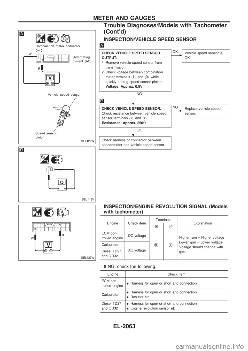
INSPECTION/VEHICLE SPEED SENSOR
CHECK VEHICLE SPEED SENSOR
OUTPUT.
1. Remove vehicle speed sensor from
transmission.
2. Check voltage between combination
meter terminals
V7andV15while
quickly turning speed sensor pinion.
Voltage: Approx. 0.5V
NG
cOK
Vehicle speed sensor is
OK.
CHECK VEHICLE SPEED SENSOR.
Check resistance between vehicle speed
sensor terminals
V1andV2.
Resistance: Approx. 250W
OK
cNG
Replace vehicle speed
sensor.
Check harness or connector between
speedometer and vehicle speed sensor.
INSPECTION/ENGINE REVOLUTION SIGNAL (Models
with tachometer)
Engine Check itemTerminals
ExplanationÅ@
ECM con-
trolled engineDC voltage
V16V3
Higher rpm = Higher voltage
Lower rpm = Lower voltage
Voltage should change with
rpm. Carburetor
AC voltage
Diesel TD27
and QD32
If NG, check the following.
Engine Check item
ECM con-
trolled engine
lHarness for open or short and connection
Carburetor
lHarness for open or short and connection
lResistor etc.
Diesel TD27
and QD32
lHarness for open or short and connection
lEngine revolution sensor etc.
SEL422W
SEL118V
SEL423W
.
.
METER AND GAUGES
Trouble Diagnoses/Models with Tachometer
(Cont'd)
EL-2063
Page 438 of 666
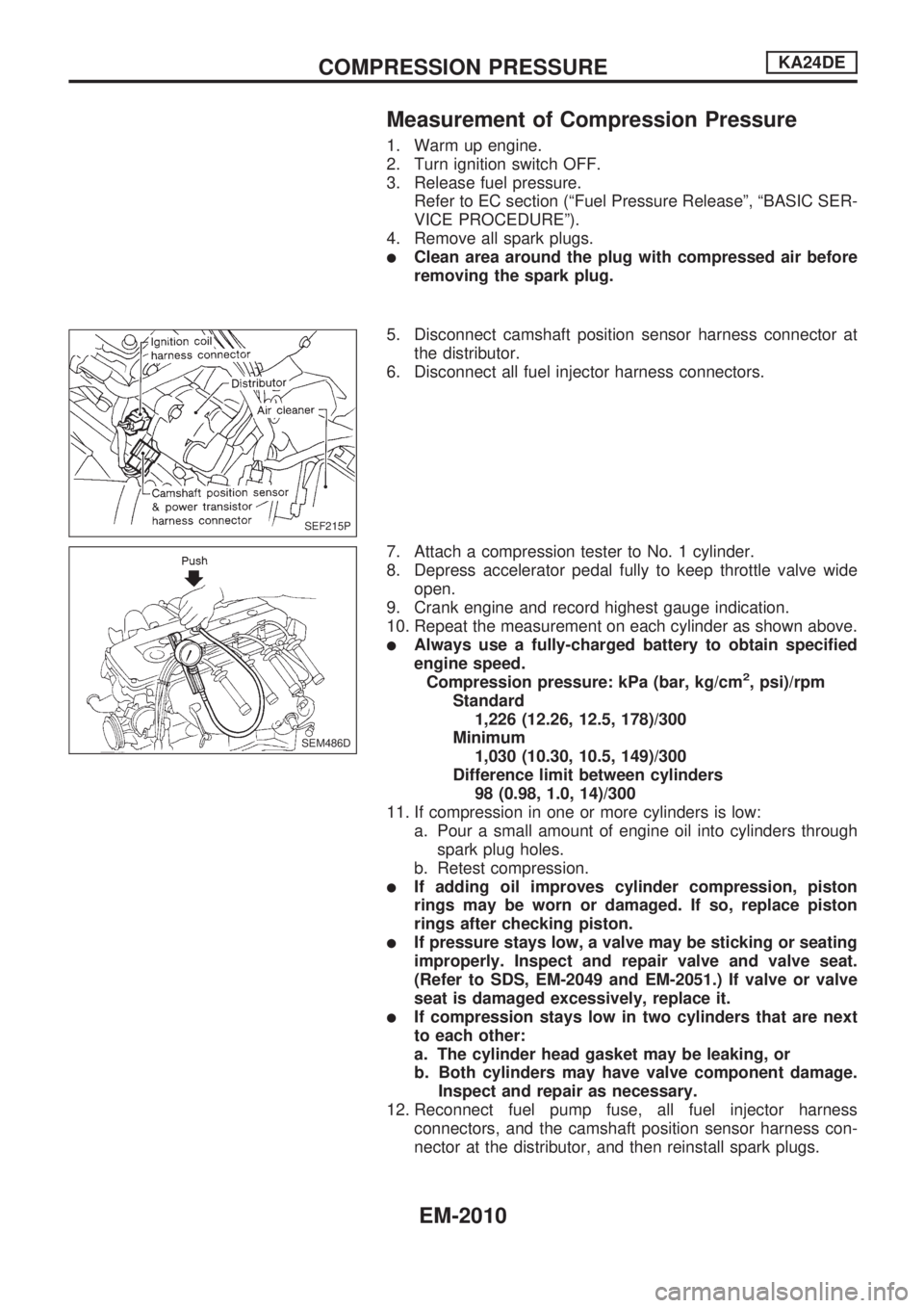
Measurement of Compression Pressure
1. Warm up engine.
2. Turn ignition switch OFF.
3. Release fuel pressure.
Refer to EC section (ªFuel Pressure Releaseº, ªBASIC SER-
VICE PROCEDUREº).
4. Remove all spark plugs.
lClean area around the plug with compressed air before
removing the spark plug.
5. Disconnect camshaft position sensor harness connector at
the distributor.
6. Disconnect all fuel injector harness connectors.
7. Attach a compression tester to No. 1 cylinder.
8. Depress accelerator pedal fully to keep throttle valve wide
open.
9. Crank engine and record highest gauge indication.
10. Repeat the measurement on each cylinder as shown above.
lAlways use a fully-charged battery to obtain specified
engine speed.
Compression pressure: kPa (bar, kg/cm
2, psi)/rpm
Standard
1,226 (12.26, 12.5, 178)/300
Minimum
1,030 (10.30, 10.5, 149)/300
Difference limit between cylinders
98 (0.98, 1.0, 14)/300
11. If compression in one or more cylinders is low:
a. Pour a small amount of engine oil into cylinders through
spark plug holes.
b. Retest compression.
lIf adding oil improves cylinder compression, piston
rings may be worn or damaged. If so, replace piston
rings after checking piston.
lIf pressure stays low, a valve may be sticking or seating
improperly. Inspect and repair valve and valve seat.
(Refer to SDS, EM-2049 and EM-2051.) If valve or valve
seat is damaged excessively, replace it.
lIf compression stays low in two cylinders that are next
to each other:
a. The cylinder head gasket may be leaking, or
b. Both cylinders may have valve component damage.
Inspect and repair as necessary.
12. Reconnect fuel pump fuse, all fuel injector harness
connectors, and the camshaft position sensor harness con-
nector at the distributor, and then reinstall spark plugs.
SEF215P
SEM486D
COMPRESSION PRESSUREKA24DE
EM-2010
Page 454 of 666
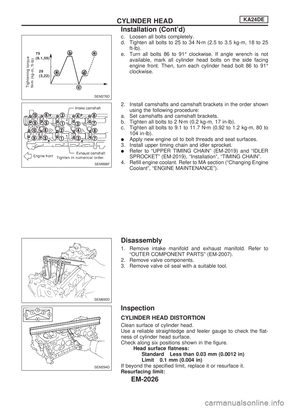
c. Loosen all bolts completely.
d. Tighten all bolts to 25 to 34 Nzm (2.5 to 3.5 kg-m, 18 to 25
ft-lb).
e. Turn all bolts 86 to 91É clockwise. If angle wrench is not
available, mark all cylinder head bolts on the side facing
engine front. Then, turn each cylinder head bolt 86 to 91É
clockwise.
2. Install camshafts and camshaft brackets in the order shown
using the following procedure:
a. Set camshafts and camshaft brackets.
b. Tighten all bolts to 2 Nzm (0.2 kg-m, 17 in-lb).
c. Tighten all bolts to 9.1 to 11.7 Nzm (0.92 to 1.2 kg-m, 80 to
104 in-lb).
lApply new engine oil to bolt threads and seat surfaces.
3. Install upper timing chain and idler sprocket.
lRefer to ªUPPER TIMING CHAINº (EM-2019) and ªIDLER
SPROCKETº (EM-2019), ªInstallationº, ªTIMING CHAINº.
4. Refill engine coolant. Refer to MA section (ªChanging Engine
Coolantº, ªENGINE MAINTENANCEº).
Disassembly
1. Remove intake manifold and exhaust manifold. Refer to
ªOUTER COMPONENT PARTSº (EM-2007).
2. Remove valve components.
3. Remove valve oil seal with a suitable tool.
Inspection
CYLINDER HEAD DISTORTION
Clean surface of cylinder head.
Use a reliable straightedge and feeler gauge to check the flat-
ness of cylinder head surface.
Check along six positions shown in the figure.
Head surface flatness:
Standard Less than 0.03 mm (0.0012 in)
Limit 0.1 mm (0.004 in)
If beyond the specified limit, replace it or resurface it.
Resurfacing limit:
SEM276D
SEM998F
SEM692D
SEM294D
CYLINDER HEADKA24DE
Installation (Cont'd)
EM-2026