1999 NISSAN PICK-UP check engine
[x] Cancel search: check enginePage 460 of 666
VALVE LIFTER AND VALVE SHIM
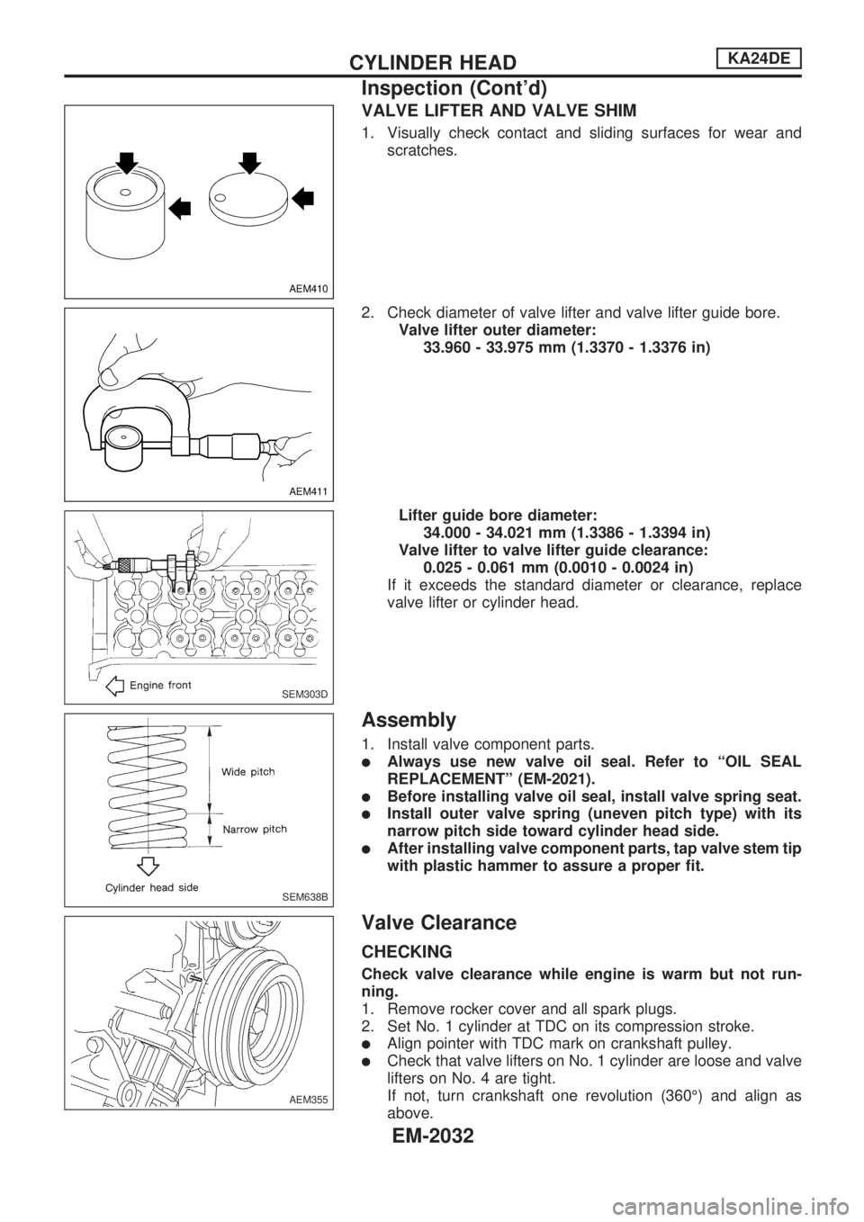
1. Visually check contact and sliding surfaces for wear and
scratches.
2. Check diameter of valve lifter and valve lifter guide bore.
Valve lifter outer diameter:
33.960 - 33.975 mm (1.3370 - 1.3376 in)
Lifter guide bore diameter:
34.000 - 34.021 mm (1.3386 - 1.3394 in)
Valve lifter to valve lifter guide clearance:
0.025 - 0.061 mm (0.0010 - 0.0024 in)
If it exceeds the standard diameter or clearance, replace
valve lifter or cylinder head.
Assembly
1. Install valve component parts.
lAlways use new valve oil seal. Refer to ªOIL SEAL
REPLACEMENTº (EM-2021).
lBefore installing valve oil seal, install valve spring seat.
lInstall outer valve spring (uneven pitch type) with its
narrow pitch side toward cylinder head side.
lAfter installing valve component parts, tap valve stem tip
with plastic hammer to assure a proper fit.
Valve Clearance
CHECKING
Check valve clearance while engine is warm but not run-
ning.
1. Remove rocker cover and all spark plugs.
2. Set No. 1 cylinder at TDC on its compression stroke.
lAlign pointer with TDC mark on crankshaft pulley.
lCheck that valve lifters on No. 1 cylinder are loose and valve
lifters on No. 4 are tight.
If not, turn crankshaft one revolution (360É) and align as
above.
AEM410
AEM411
SEM303D
SEM638B
AEM355
CYLINDER HEADKA24DE
Inspection (Cont'd)
EM-2032
Page 461 of 666
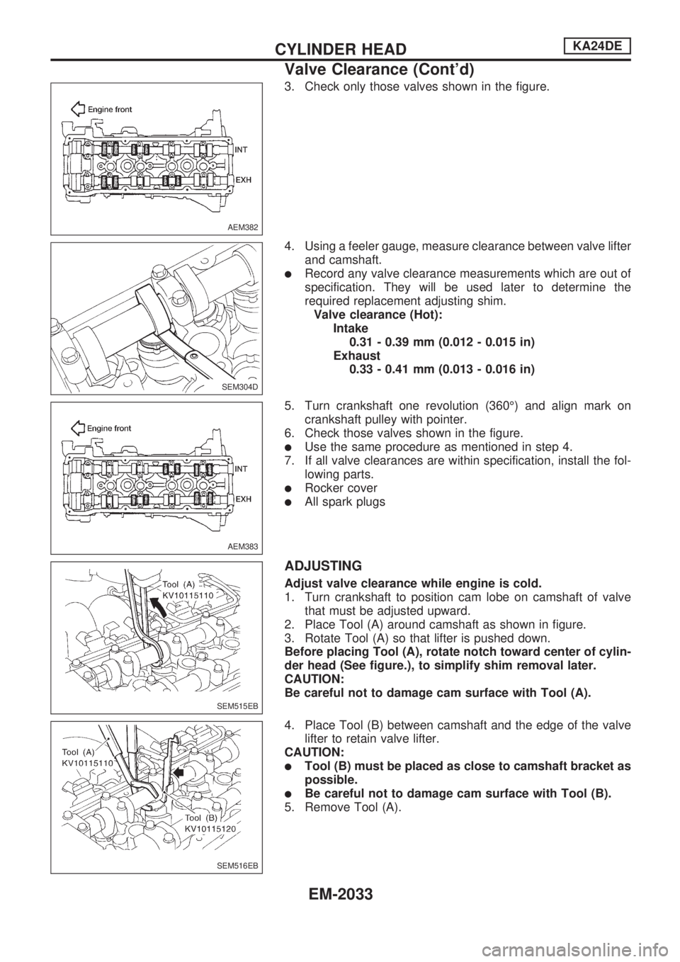
3. Check only those valves shown in the figure.
4. Using a feeler gauge, measure clearance between valve lifter
and camshaft.
lRecord any valve clearance measurements which are out of
specification. They will be used later to determine the
required replacement adjusting shim.
Valve clearance (Hot):
Intake
0.31 - 0.39 mm (0.012 - 0.015 in)
Exhaust
0.33 - 0.41 mm (0.013 - 0.016 in)
5. Turn crankshaft one revolution (360É) and align mark on
crankshaft pulley with pointer.
6. Check those valves shown in the figure.
lUse the same procedure as mentioned in step 4.
7. If all valve clearances are within specification, install the fol-
lowing parts.
lRocker cover
lAll spark plugs
ADJUSTING
Adjust valve clearance while engine is cold.
1. Turn crankshaft to position cam lobe on camshaft of valve
that must be adjusted upward.
2. Place Tool (A) around camshaft as shown in figure.
3. Rotate Tool (A) so that lifter is pushed down.
Before placing Tool (A), rotate notch toward center of cylin-
der head (See figure.), to simplify shim removal later.
CAUTION:
Be careful not to damage cam surface with Tool (A).
4. Place Tool (B) between camshaft and the edge of the valve
lifter to retain valve lifter.
CAUTION:
lTool (B) must be placed as close to camshaft bracket as
possible.
lBe careful not to damage cam surface with Tool (B).
5. Remove Tool (A).
AEM382
SEM304D
AEM383
SEM515EB
SEM516EB
CYLINDER HEADKA24DE
Valve Clearance (Cont'd)
EM-2033
Page 501 of 666
HEATER&
AIR CONDITIONER
SECTION
HA
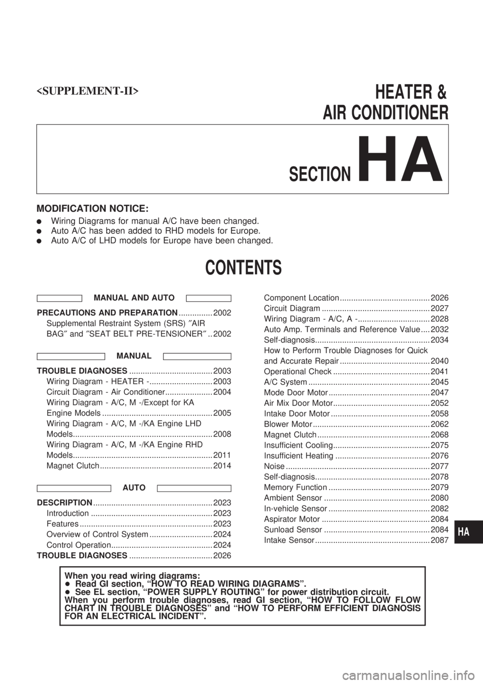
MODIFICATION NOTICE:
lWiring Diagrams for manual A/C have been changed.
lAuto A/C has been added to RHD models for Europe.
lAuto A/C of LHD models for Europe have been changed.
CONTENTS
MANUAL AND AUTO
PRECAUTIONS AND PREPARATION ............... 2002
Supplemental Restraint System (SRS) ²AIR
BAG ²and ²SEAT BELT PRE-TENSIONER ².. 2002
MANUAL
TROUBLE DIAGNOSES ..................................... 2003
Wiring Diagram - HEATER -............................ 2003
Circuit Diagram - Air Conditioner..................... 2004
Wiring Diagram - A/C, M -/Except for KA
Engine Models ................................................. 2005
Wiring Diagram - A/C, M -/KA Engine LHD
Models.............................................................. 2008
Wiring Diagram - A/C, M -/KA Engine RHD
Models.............................................................. 2011
Magnet Clutch .................................................. 2014
AUTO
DESCRIPTION..................................................... 2023
Introduction ...................................................... 2023
Features ........................................................... 2023
Overview of Control System ............................ 2024
Control Operation............................................. 2024
TROUBLE DIAGNOSES ..................................... 2026 Component Location ........................................ 2026
Circuit Diagram ................................................ 2027
Wiring Diagram - A/C, A -................................ 2028
Auto Amp. Terminals and Reference Value .... 2032
Self-diagnosis................................................... 2034
How to Perform Trouble Diagnoses for Quick
and Accurate Repair ........................................ 2040
Operational Check ........................................... 2041
A/C System ...................................................... 2045
Mode Door Motor ............................................. 2047
Air Mix Door Motor........................................... 2052
Intake Door Motor ............................................ 2058
Blower Motor .................................................... 2062
Magnet Clutch .................................................. 2068
Insufficient Cooling........................................... 2075
Insufficient Heating .......................................... 2076
Noise ................................................................ 2077
Self-diagnosis................................................... 2078
Memory Function ............................................. 2079
Ambient Sensor ............................................... 2080
In-vehicle Sensor ............................................. 2082
Aspirator Motor ................................................ 2084
Sunload Sensor ............................................... 2084
Intake Sensor ................................................... 2087
When you read wiring diagrams:
+
Read GI section, ªHOW TO READ WIRING DIAGRAMSº.
+ See EL section, ªPOWER SUPPLY ROUTINGº for power distribution circuit.
When you perform trouble diagnoses, read GI section, ªHOW TO FOLLOW FLOW
CHART IN TROUBLE DIAGNOSESº and ªHOW TO PERFORM EFFICIENT DIAGNOSIS
FOR AN ELECTRICAL INCIDENTº.
HA
Page 514 of 666
Magnet Clutch
DIAGNOSTIC PROCEDURE
Except for KA engine models
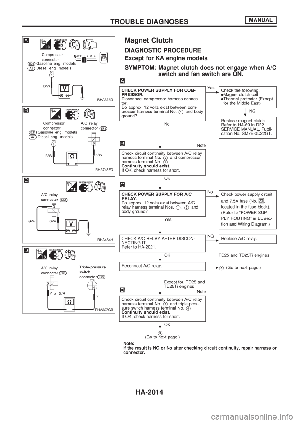
SYMPTOM: Magnet clutch does not engage when A/C
switch and fan switch are ON.
CHECK POWER SUPPLY FOR COM-
PRESSOR.
Disconnect compressor harness connec-
tor.
Do approx. 12 volts exist between com-
pressor harness terminal No.
V1and body
ground?
No
cYes
Check the following.
lMagnet clutch coillThermal protector (Except
for the Middle East)
NG
Replace magnet clutch.
Refer to HA-69 in D22
SERVICE MANUAL, Publi-
cation No. SM7E-0D22G1.
Note
Check circuit continuity between A/C relay
harness terminal No.
V5and compressor
harness terminal No.
V1.
Continuity should exist.
If OK, check harness for short.
OK
CHECK POWER SUPPLY FOR A/C
RELAY.
Do approx. 12 volts exist between A/C
relay harness terminal Nos.
V1,V3and
body ground?
Yes
cNo
Check power supply circuit
and 7.5A fuse (No.
23,
located in the fuse block).
(Refer to ªPOWER SUP-
PLY ROUTINGº in EL sec-
tion and Wiring Diagram.)
CHECK A/C RELAY AFTER DISCON-
NECTING IT.
Refer to HA-2021.
OK
cNG
Replace A/C relay.
TD25 and TD25Ti engines
Reconnect A/C relay.
cVA(Go to next page.)
Except for, TD25 and
TD25Ti engines
Note
Check circuit continuity between A/C relay
harness terminal No.
V2and triple-pres-
sure switch harness terminal No.
V4.
Continuity should exist.
If OK, check harness for short.
OK
VB(Go to next page.)
Note:
If the result is NG or No after checking circuit continuity, repair harness or
connector.
RHA325G
RHA748FD
RHA464H
RHA327GB
.
.
.
.
.
.
.
TROUBLE DIAGNOSESMANUAL
HA-2014
Page 517 of 666
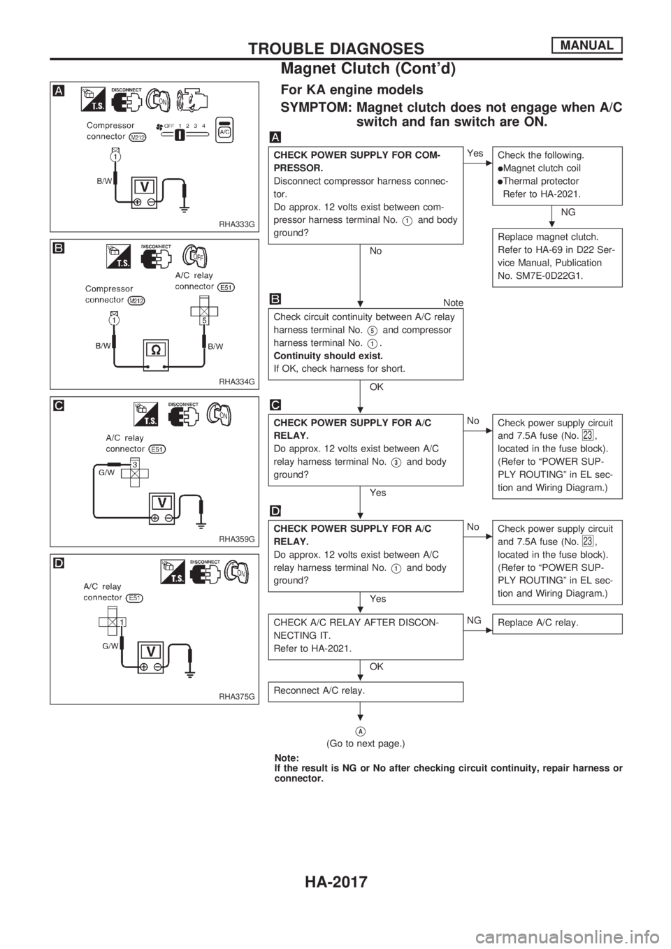
For KA engine models
SYMPTOM: Magnet clutch does not engage when A/C
switch and fan switch are ON.
CHECK POWER SUPPLY FOR COM-
PRESSOR.
Disconnect compressor harness connec-
tor.
Do approx. 12 volts exist between com-
pressor harness terminal No.
V1and body
ground?
No
cYes
Check the following.
lMagnet clutch coil
lThermal protector
Refer to HA-2021.
NG
Replace magnet clutch.
Refer to HA-69 in D22 Ser-
vice Manual, Publication
No. SM7E-0D22G1.
Note
Check circuit continuity between A/C relay
harness terminal No.
V5and compressor
harness terminal No.
V1.
Continuity should exist.
If OK, check harness for short.
OK
CHECK POWER SUPPLY FOR A/C
RELAY.
Do approx. 12 volts exist between A/C
relay harness terminal No.
V3and body
ground?
Yes
cNo
Check power supply circuit
and 7.5A fuse (No.
23,
located in the fuse block).
(Refer to ªPOWER SUP-
PLY ROUTINGº in EL sec-
tion and Wiring Diagram.)
CHECK POWER SUPPLY FOR A/C
RELAY.
Do approx. 12 volts exist between A/C
relay harness terminal No.
V1and body
ground?
Yes
cNo
Check power supply circuit
and 7.5A fuse (No.
23,
located in the fuse block).
(Refer to ªPOWER SUP-
PLY ROUTINGº in EL sec-
tion and Wiring Diagram.)
CHECK A/C RELAY AFTER DISCON-
NECTING IT.
Refer to HA-2021.
OK
cNG
Replace A/C relay.
Reconnect A/C relay.
VA
(Go to next page.)
Note:
If the result is NG or No after checking circuit continuity, repair harness or
connector.
RHA333G
RHA334G
RHA359G
RHA375G
.
.
.
.
.
.
.
TROUBLE DIAGNOSESMANUAL
Magnet Clutch (Cont'd)
HA-2017
Page 534 of 666
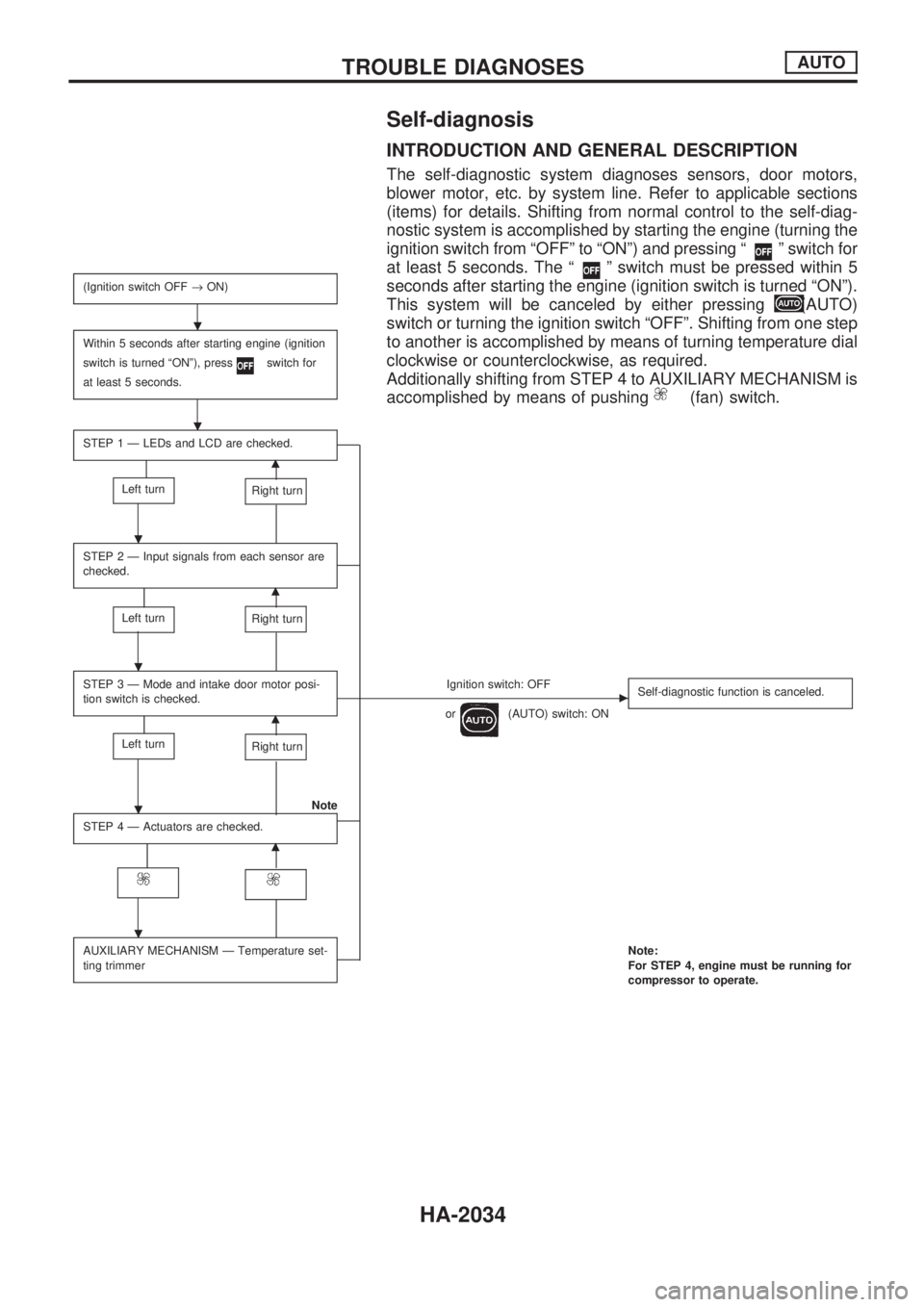
Self-diagnosis
INTRODUCTION AND GENERAL DESCRIPTION
The self-diagnostic system diagnoses sensors, door motors,
blower motor, etc. by system line. Refer to applicable sections
(items) for details. Shifting from normal control to the self-diag-
nostic system is accomplished by starting the engine (turning the
ignition switch from ªOFFº to ªONº) and pressing ª
º switch for
at least 5 seconds. The ª
º switch must be pressed within 5
seconds after starting the engine (ignition switch is turned ªONº).
This system will be canceled by either pressing
(AUTO)
switch or turning the ignition switch ªOFFº. Shifting from one step
to another is accomplished by means of turning temperature dial
clockwise or counterclockwise, as required.
Additionally shifting from STEP 4 to AUXILIARY MECHANISM is
accomplished by means of pushing
(fan) switch.
(Ignition switch OFF®ON)
Within 5 seconds after starting engine (ignition
switch is turned ªONº), press
switch for
at least 5 seconds.
STEP 1 Ð LEDs and LCD are checked.
m
Left turnRight turn
STEP 2 Ð Input signals from each sensor are
checked.
m
Left turnRight turn
STEP 3 Ð Mode and intake door motor posi-
tion switch is checked.Ignition switch: OFFc
or(AUTO) switch: ONSelf-diagnostic function is canceled.m
Left turnRight turn
Note
STEP 4 Ð Actuators are checked.
m
AUXILIARY MECHANISM Ð Temperature set-
ting trimmerNote:
For STEP 4, engine must be running for
compressor to operate.
.
.
.
.
.
.
TROUBLE DIAGNOSESAUTO
HA-2034
Page 535 of 666
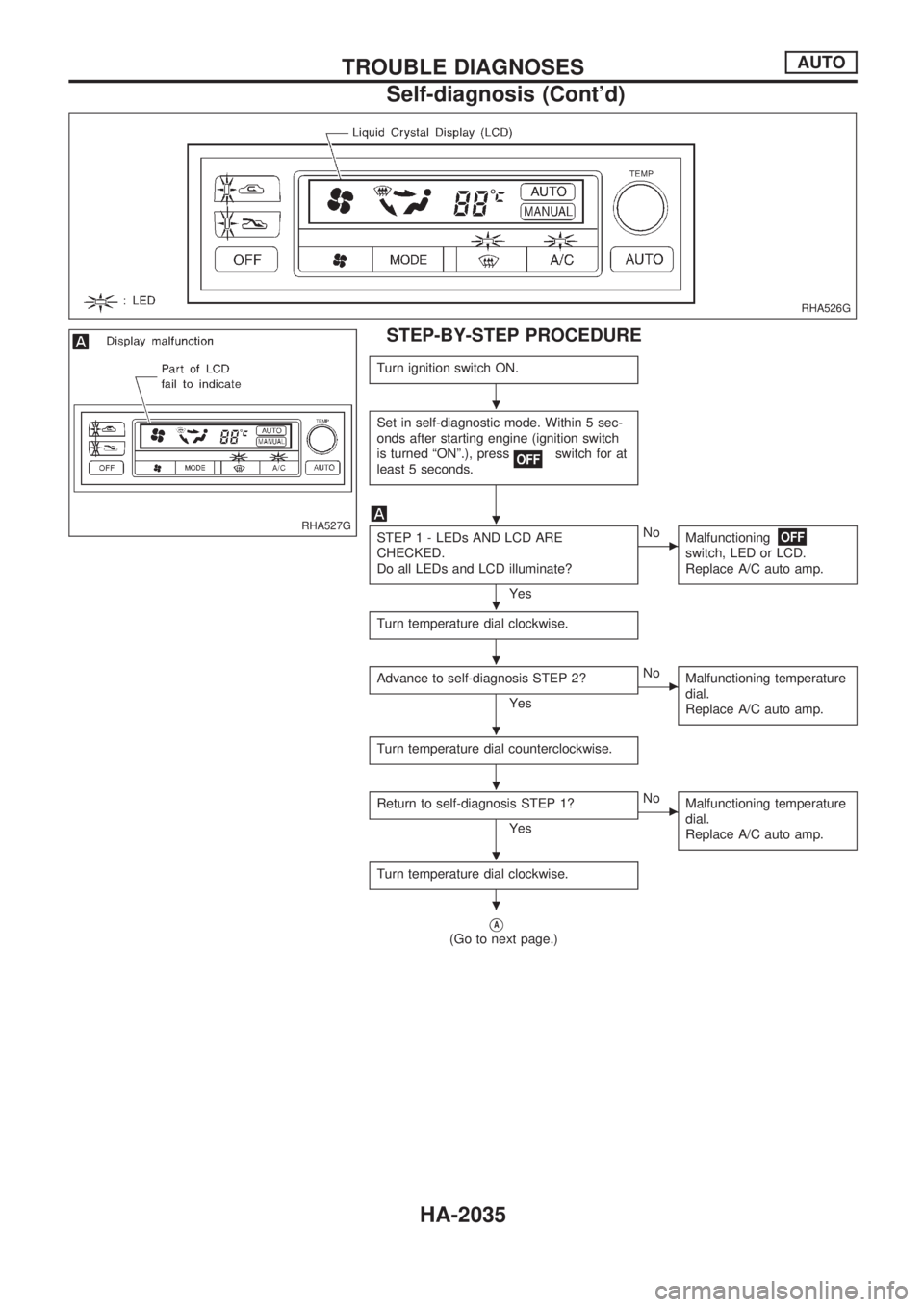
STEP-BY-STEP PROCEDURE
Turn ignition switch ON.
Set in self-diagnostic mode. Within 5 sec-
onds after starting engine (ignition switch
is turned ªONº.), press
switch for at
least 5 seconds.
STEP 1 - LEDs AND LCD ARE
CHECKED.
Do all LEDs and LCD illuminate?
Yes
cNo
Malfunctioning
switch, LED or LCD.
Replace A/C auto amp.
Turn temperature dial clockwise.
Advance to self-diagnosis STEP 2?
Yes
cNo
Malfunctioning temperature
dial.
Replace A/C auto amp.
Turn temperature dial counterclockwise.
Return to self-diagnosis STEP 1?
Yes
cNo
Malfunctioning temperature
dial.
Replace A/C auto amp.
Turn temperature dial clockwise.
VA(Go to next page.)
RHA526G
RHA527G
.
.
.
.
.
.
.
.
TROUBLE DIAGNOSESAUTO
Self-diagnosis (Cont'd)
HA-2035
Page 538 of 666
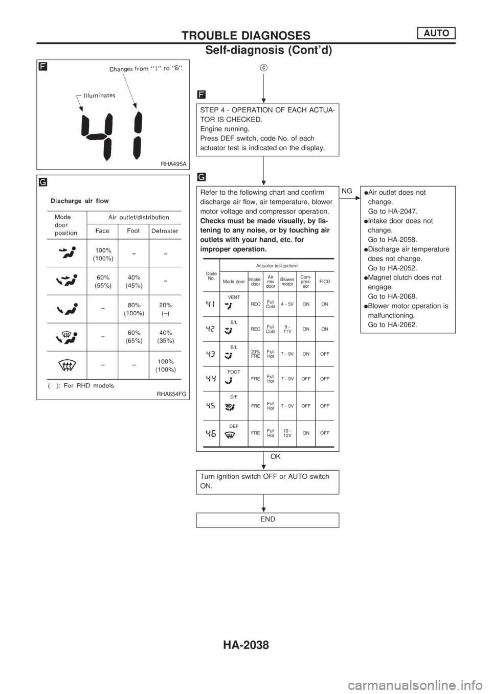
VC
STEP 4 - OPERATION OF EACH ACTUA-
TOR IS CHECKED.
Engine running.
Press DEF switch, code No. of each
actuator test is indicated on the display.
Refer to the following chart and confirm
discharge air flow, air temperature, blower
motor voltage and compressor operation.
Checks must be made visually, by lis-
tening to any noise, or by touching air
outlets with your hand, etc. for
improper operation.
OK
cNGlAir outlet does not
change.
Go to HA-2047.
lIntake door does not
change.
Go to HA-2058.
lDischarge air temperature
does not change.
Go to HA-2052.
lMagnet clutch does not
engage.
Go to HA-2068.
lBlower motor operation is
malfunctioning.
Go to HA-2062.
Turn ignition switch OFF or AUTO switch
ON.
END
Code
No.Actuator test pattern
Mode doorIntake
doorAir
mix
doorBlower
motorCom-
pres-
sorFICD
VENTRECFull
Cold4-5V ON ON
B/LRECFull
Cold9-
11VON ON
B/L20%
FREFull
Hot7-9V ON OFF
FOOTFREFull
Hot7 - 9V OFF OFF
D/F
FREFull
Hot7 - 9V OFF OFF
DEFFREFull
Hot10 -
12VON OFF
RHA495A
RHA654FG
.
.
.
.
TROUBLE DIAGNOSESAUTO
Self-diagnosis (Cont'd)
HA-2038