Page 70 of 558

ENGINE – Cylinder Head and Valves11-45
(3) How to Neutralize Sodium
Place a container filled with more than 10 liters of water
in a well ventilated large space.
Wear rubber gloves and goggles, and carefully take out
broken valves from the cylinder head.
Put a broken valve in the water-filled container and quickly
get away from the container at least 2 or 3 m.
Caution
1. Valves must be neutralized one at a time.
2. Put a valve in the container only after soduim
in the preceding one has completely reacted with
water.
Keep fire away from the container during the
neutralization. The resulting hydrogen gas is highly
explosive.
When the reaction has finished (there is no more
generation of hydrogen gas), take the valves out of the
container with large tweezers or the like.
NOTE
The reaction occurs when water enters the cavity in the
valve. Hydrogen gas may be trapped inside the valve,
temporarily blocking the water passage. In such a case,
wait until hydrogen gas in released and remaining soduim
reacts with water.
After the neutralization of soduim, water in the container
contains soduim hydroxide and is highly alkaline. The
water solution should be disposed of according to local
regulations.
Caution
1. Do not let the solution contact the eyes or the
skin.
2. Should it get in the eyes, immediately flush them
with clean water thoroughly, and receive medical
attention. When it contacts the skin, wash with
ample amounts of clean water.
INSTALLATION SERVICE POINTS
�A�VALVE STEM SEAL INSTALLATION
(1) Install the valve spring seat.
(2) The special tool must be used to install the valve stem
seal. Improper installation could result in oil leaks past
the valve guide.
Caution
Do not reuse removed valve stem seals.
MD998737
Page 71 of 558
ENGINE – Cylinder Head and Valves11-46
�B�VALVE SPRING INSTALLATION
Direct the valve spring end with identification color toward
the spring retainer.
�C�RETAINER LOCK INSTALLATION
The valve spring, if excessively compressed, causes the
bottom end of the retainer to be in contact with, and damage,
the stem seal.
�D�CYLINDER HEAD BOLT INSTALLATION
(1) When installing the cylinder head bolts, check that the
shank length of each bolt meets the limit. If the limit is
exceeded, replace the bolt.
Limit: Max. 99.4 mm
(2) Apply engine oil to the bolt threads and to the washers.
(3) Using the special tool (MB991654) and according to the
tightening sequence, tighten the bolts to the specified
torque.
Tightening torque: 78 Nm
(4) Loosen all bolts fully.
(5) Retighten the loosened bolts to a torque of 20 Nm in
the specified tightening sequence.
MD998772
MD998735
6EN0782
Shank length
Timing belt side
Page 72 of 558

ENGINE – Cylinder Head and Valves11-47
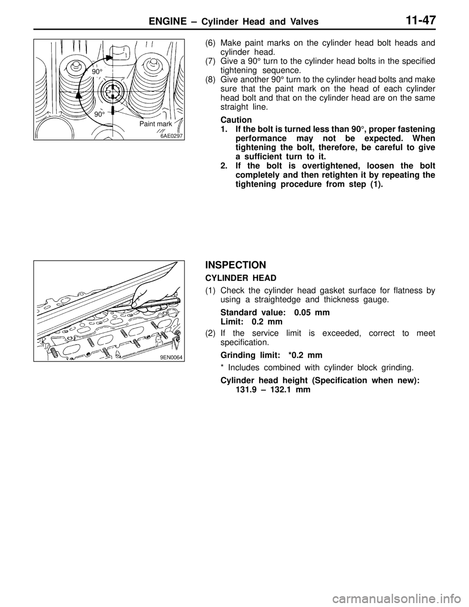
(6) Make paint marks on the cylinder head bolt heads and
cylinder head.
(7) Give a 90° turn to the cylinder head bolts in the specified
tightening sequence.
(8) Give another 90° turn to the cylinder head bolts and make
sure that the paint mark on the head of each cylinder
head bolt and that on the cylinder head are on the same
straight line.
Caution
1. If the bolt is turned less than 90°, proper fastening
performance may not be expected. When
tightening the bolt, therefore, be careful to give
a sufficient turn to it.
2. If the bolt is overtightened, loosen the bolt
completely and then retighten it by repeating the
tightening procedure from step (1).
INSPECTION
CYLINDER HEAD
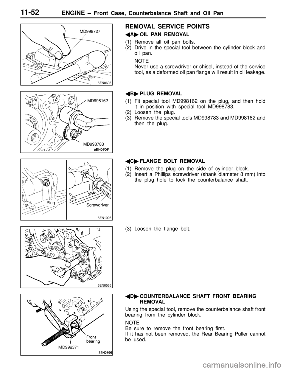
(1) Check the cylinder head gasket surface for flatness by
using a straightedge and thickness gauge.
Standard value: 0.05 mm
Limit: 0.2 mm
(2) If the service limit is exceeded, correct to meet
specification.
Grinding limit: *0.2 mm
* Includes combined with cylinder block grinding.
Cylinder head height (Specification when new):
131.9 – 132.1 mm
6AE0297
90°
Paint mark
90°
9EN0064
Page 75 of 558
ENGINE – Cylinder Head and Valves11-50
VALVE GUIDE REPLACEMENT PROCEDURE
(1) Force the valve guide out toward the cylinder block using
a press.
(2) Machine the valve guide hole in the cylinder head to
the size of the oversize valve guide to be installed.
Caution
Do not use the valve guide of the same size as the
removed one.
Valve gauge hole diameters in cylinder head
ItemStandard value mm
0.05 O.S.12.05 – 12.07
0.25 O.S.12.25 – 12.27
0.50 O.S.12.50 – 12.52
(3) Press-fit the valve guide until it protrude specified value
19.5 mm as shown in the illustration.
Caution
1. Press the valve guide from the cylinder head top
surface.
2. Valve guide for intake valve and that for exhaust
valve are different in length. (45.5 mm for intake
valve; 50.5 mm for exhaust valve)
(4) After the valve guide has been installed, insert a new
valve to check for smooth sliding motion.
1EN0106
Protrusion
Page 77 of 558

ENGINE – Front Case, Counterbalance Shaft and Oil Pan11-52
REMOVAL SERVICE POINTS
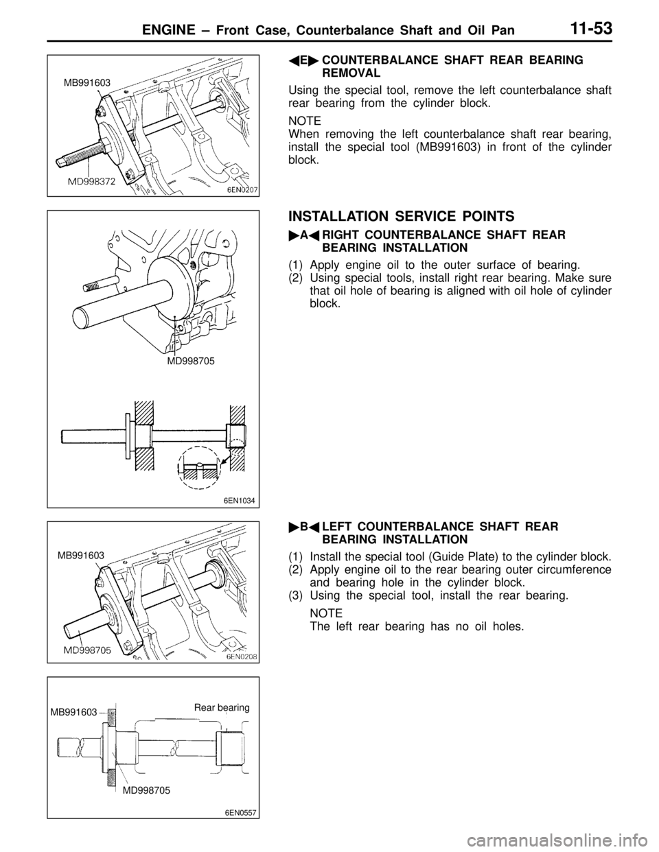
�A�OIL PAN REMOVAL
(1) Remove all oil pan bolts.
(2) Drive in the special tool between the cylinder block and
oil pan.
NOTE
Never use a screwdriver or chisel, instead of the service
tool, as a deformed oil pan flange will result in oil leakage.
�B�PLUG REMOVAL
(1) Fit special tool MD998162 on the plug, and then hold
it in position with special tool MD998783.
(2) Loosen the plug.
(3) Remove the special tools MD998783 and MD998162 and
then the plug.
�C�FLANGE BOLT REMOVAL
(1) Remove the plug on the side of cylinder block.
(2) Insert a Phillips screwdriver (shank diameter 8 mm) into
the plug hole to lock the counterbalance shaft.
(3) Loosen the flange bolt.
�D�COUNTERBALANCE SHAFT FRONT BEARING
REMOVAL
Using the special tool, remove the counterbalance shaft front
bearing from the cylinder block.
NOTE
Be sure to remove the front bearing first.
If it has not been removed, the Rear Bearing Puller cannot
be used.
6EN0698
MD998727
MD998162
MD998783
6EN1026
Plug
Screwdriver
6EN0565
Page 78 of 558

ENGINE – Front Case, Counterbalance Shaft and Oil Pan11-53
�E�COUNTERBALANCE SHAFT REAR BEARING
REMOVAL
Using the special tool, remove the left counterbalance shaft
rear bearing from the cylinder block.
NOTE
When removing the left counterbalance shaft rear bearing,
install the special tool (MB991603) in front of the cylinder
block.
INSTALLATION SERVICE POINTS
�A�RIGHT COUNTERBALANCE SHAFT REAR
BEARING INSTALLATION
(1) Apply engine oil to the outer surface of bearing.
(2) Using special tools, install right rear bearing. Make sure
that oil hole of bearing is aligned with oil hole of cylinder
block.
�B�LEFT COUNTERBALANCE SHAFT REAR
BEARING INSTALLATION
(1) Install the special tool (Guide Plate) to the cylinder block.
(2) Apply engine oil to the rear bearing outer circumference
and bearing hole in the cylinder block.
(3) Using the special tool, install the rear bearing.
NOTE
The left rear bearing has no oil holes.
MB991603
6EN1034
MD998705
MB991603
6EN0557
MB991603Rear bearing
MD998705
Page 79 of 558
ENGINE – Front Case, Counterbalance Shaft and Oil Pan11-54
�C�COUNTERBALANCE SHAFT FRONT BEARING
INSTALLATION
Using special tools, install front bearing.
�D�COUNTERBALANCE SHAFT OIL SEAL
INSTALLATION
Using a suitable socket wrench, install the counterbalance
shaft oil seal into the front case.
�E�OIL PUMP OIL SEAL INSTALLATION
Using a suitable socket wrench, install the oil pump oil seal
into the front case.
�F�CRANKSHAFT FRONT OIL SEAL INSTALLATION
Using the special tool, install the crankshaft front oil seal
into the front case.
6EN1035
MD998705
MD998705
Bearing
Cylinder block
Page 80 of 558
ENGINE – Front Case, Counterbalance Shaft and Oil Pan11-55
�G�OIL PUMP DRIVEN GEAR / OIL PUMP DRIVE
GEAR INSTALLATION
Apply engine oil amply to the gears and line up the alignment
marks.
�H�FRONT CASE ASSEMBLY INSTALLATION
(1) Set the special tool on the front end of crankshaft and
apply a thin coat of engine oil to the outer circumference
of the special tool to install the front case.
(2) Install the front case assembly through a new front case
gasket and temporarily tighten the flange bolts (other
than those for tightening the filter bracket).
�I�SEALANT APPLICATION TO OIL PRESSURE
SWITCH
Coat the threads of switch with sealant and install the switch
using the special tool.
Specified sealant: 3M
TM AAD Part No. 8672 or equivalent
Caution
(1) Keep the end of the thread portion clear or sealant.
(2) Avoid an overtightening.
�J�FLANGE BOLT INSTALLATION
(1) Insert a Phillips screwdriver into a hole in the left side
of the cylinder block to lock the silent shaft.
6EN0564