Page 44 of 558
ENGINE – Timing Belt11-19
�D�SEALANT APPLICATION TO ROCKER COVER
Apply sealant to the areas indicated in the illustration.
Specified sealant: 3M
TM AAD Part No. 8672 or equivalent
Apply sealantApply sealant
Apply sealant 10 mm
10 mm
10 mm
10 mm
Apply sealant
�E�SPACER INSTALLATION
Install the spacer with the chamfered end toward the oil seal.
�F�COUNTERBALANCE SHAFT SPROCKET
INSTALLATION
(1) Install the counterbalance shaft sprocket and screw the
bolt.
(2) Install special tool MD998785 as shown in the illustration
to lock the counterbalance shaft.
(3) Tighten the bolt, and then remove the special tool.
Counter-
balance
shaft
Sharp
edge
MD998785
Page 46 of 558

ENGINE – Timing Belt11-21
�I�OIL PUMP SPROCKET INSTALLATION
(1) Insert a Phillips screwdriver (shank diameter 8 mm shaft)
through the plug hole on the left side of the cylinder
block to block the left counterbalance shaft.
(2) Install the oil pump sprocket.
(3) Apply a proper amount of engine oil to the bearing surfaces
of the nuts.
(4) Tighten the nuts to the specified torque.
�J�AUTO TENSIONER INSTALLATION
(1) If the auto tensioner rod is in its fully extended position,
reset it as follows.
(2) Clamp the auto-tensioner in the vise with soft jaws.
(3) Push in the rod little by little with the vise until the set
hole A in the rod is aligned with the hole B in the cylinder.
(4) Insert a wire (1.4 mm in diameter) into the set holes.
(5) Unclamp the auto tensioner from the vise.
(6) Install the auto tensioner to front case and tighten to
the specified torque.
Caution
Leave the wire installed in the auto tensioner.
�K�TENSIONER PULLEY INSTALLATION
Install the tensioner pulley in such direction that its two small
holes are arranged vertically.
6EN0564
A
B
6EN1323
Small holes
Page 47 of 558

ENGINE – Timing Belt11-22
�L�TIMING BELT INSTALLATION
(1) Place the exhaust side camshaft sprocket in a position
where its timing mark is one tooth offset from the timing
mark on the rocker cover in the counterclockwise direction.
NOTE
Even if the timing marks on the sprocket and the rocker
cover are brought into alignment, the exhaust camshaft
is forced back by the valve spring tension. It is stabilized
at a position one tooth before the timing mark.
(2) Align the timing mark on the intake side camshaft sprocket
with that on the rocker cover.
NOTE
Even if the timing marks on the sprocket and the cover
are brought into alignment, the intake camshaft is forced
to turn one tooth in the clockwise direction by the valve
spring tension and stabilized there.
(3) Place the timing mark on the crankshaft sprocket one
tooth this side from the mated timing mark as in the case
of the camshaft sprocket.
(4) Align the timing mark on oil pump sprocket with its mating
mark.
(5) Remove the plug on cylinder block and insert a Phillips
screwdriver (shank diameter 8 mm) through the hole
(Engine with counterbalance shafts).
If it can be inserted as deep as 60 mm or more, the
timing marks are correctly aligned. If the inserted depth
is only 20 – 25 mm, turn the oil pump sprocket one turn
and realign timing marks. Then check to ensure that the
screwdriver can be inserted 60 mm or more. Keep the
screwdriver inserted until installation of timing belt is
finished.
Timing mark
Timing mark
6EN1327
Oil pump
sprocket
timing marks
Screwdriver
6EN1026
Plug
Page 48 of 558

ENGINE – Timing Belt11-23
(6) Remove the Phillips screwdriver. Place the oil pump
sprocket in a position where its timing mark is one tooth
offset from the mated timing mark in the counterclockwise
direction.
(7) Fit the timing belt over the exhaust side camshaft sprocket,
and secure it at the illustrated position using a paper
clip.
(8) Turn the intake side camshaft sprocket as shown to a
position where its timing mark is one tooth offset from
the mated timing mark in the counterclockwise direction.
Then, fit the timing belt over the sprocket and secure
it with a paper clip.
NOTE
The intake camshaft will be turned a little clockwise by
the valve spring tension and stabilized in position even
if the belt is clipped at one tooth offset position.
(9) Check to ensure that the timing marks on the intake
camshaft sprocket side are in alignment when the exhaust
camshaft sprocket is turned clockwise to align the timing
marks.
NOTE
The timing belt span between the intake and exhaust
sprockets will have 17 cogs.
(10)Fit the timing belt over the idler pulley, oil pump sprocket
and crankshaft sprocket in this order.
NOTE
Be careful that the belt does not become slack.
Timing mark
6EN1327
Timing mark
Crankshaft
sprocketOil pump
sprocket
Page 49 of 558

ENGINE – Timing Belt11-24
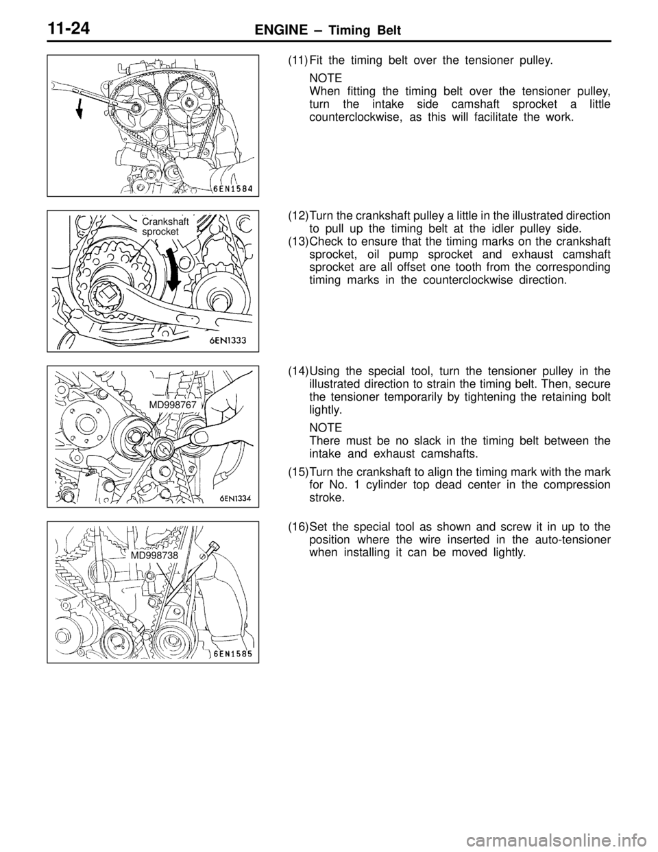
(11) Fit the timing belt over the tensioner pulley.
NOTE
When fitting the timing belt over the tensioner pulley,
turn the intake side camshaft sprocket a little
counterclockwise, as this will facilitate the work.
(12)Turn the crankshaft pulley a little in the illustrated direction
to pull up the timing belt at the idler pulley side.
(13)Check to ensure that the timing marks on the crankshaft
sprocket, oil pump sprocket and exhaust camshaft
sprocket are all offset one tooth from the corresponding
timing marks in the counterclockwise direction.
(14)Using the special tool, turn the tensioner pulley in the
illustrated direction to strain the timing belt. Then, secure
the tensioner temporarily by tightening the retaining bolt
lightly.
NOTE
There must be no slack in the timing belt between the
intake and exhaust camshafts.
(15)Turn the crankshaft to align the timing mark with the mark
for No. 1 cylinder top dead center in the compression
stroke.
(16)Set the special tool as shown and screw it in up to the
position where the wire inserted in the auto-tensioner
when installing it can be moved lightly.
Crankshaft
sprocket
MD998767
MD998738
Page 50 of 558

ENGINE – Timing Belt11-25
(17)Loosen the retaining bolt of the tensioner pulley.
Caution
Loosening the retaining bolt can cause the intake
and exhaust camshafts to turn, resulting in slackened
timing belt. Use care that the timing belt does not
come off the sprockets at this time.
(18)Pull up the slack of the timing belt by turning the tensioner
in illustrated direction using the special tool and a torque
wrench (0 – 5 Nm).
(19)From this position, turn back the tensioner until the torque
wrench reading becomes 3.5 Nm, then secure it by
tightening the retaining bolt.
(20)Remove the special tool attached in step (16).
(21)Rotate the crankshaft clockwise 2 turns. Then, leave it
intact 15 minutes.
(22)Check to see that the wire inserted when installing the
auto-tensioner can be pulled out lightly. If it can be pulled
out lightly, the timing belt is being tensioned properly.
If so, remove the wire. In addition, check that the rod
protrusion from the auto-tensioner meets the standard
value, which is also an indication of properly tensioned
timing belt.
Standard value: 3.8 – 4.5 mm
(23)If the wire cannot be removed with a light force, repeat
steps (16) through (21) until the proper belt tensioner
is obtained.
INSPECTION
TIMING BELT
Replace belt if any of the following conditions exist.
(1) Hardening of back rubber.
Back side is glossy without resilience and leaves no indent
when pressed with fingernail.
(2) Cracks on rubber back.
(3) Cracks or peeling of canvas.
(4) Cracks on rib root.
(5) Cracks on belt sides.
MD998767
Page 68 of 558
ENGINE – Cylinder Head and Valves11-43
CYLINDER HEAD AND VALVES
REMOVAL AND INSTALLATION
Apply engine oil to all
moving parts before
installation.78 Nm → Loosen completely → 20 Nm + 90� + 90�
1
2
3 4
5
6
78
9
10
11 12
1314
15
1617
1819 20
Removal steps
�A��D�1. Cylinder head bolt
2. Cylinder head assembly
3. Cylinder head gasket
�B��C�4. Retainer lock
5. Valve spring retainer
�B�6. Valve spring
7. Intake valve
�B��C�8. Retainer lock
9. Valve spring retainer
�B�10. Valve spring�C�11. Exhaust valve
�A�12. Valve stem seal
13. Valve spring seat
�A�14. Valve stem seal
15. Valve spring seat
16. Intake valve guide
17. Exhaust valve guide
18. Intake valve seat
19. Exhaust valve seat
20. Cylinder head
Page 69 of 558

ENGINE – Cylinder Head and Valves11-44
REMOVAL SERVICE POINTS
PRECAUTION FOR REMOVED PARTS
Keep removed parts in order according to the cylinder number
and intake/exhaust.
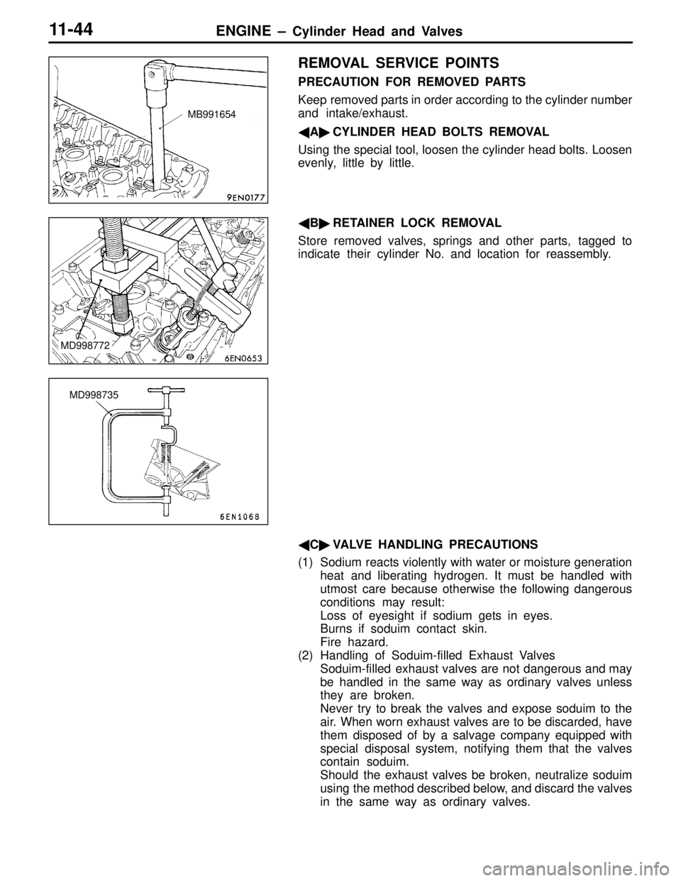
�A�CYLINDER HEAD BOLTS REMOVAL
Using the special tool, loosen the cylinder head bolts. Loosen
evenly, little by little.
�B�RETAINER LOCK REMOVAL
Store removed valves, springs and other parts, tagged to
indicate their cylinder No. and location for reassembly.
�C�VALVE HANDLING PRECAUTIONS
(1) Sodium reacts violently with water or moisture generation
heat and liberating hydrogen. It must be handled with
utmost care because otherwise the following dangerous
conditions may result:
Loss of eyesight if sodium gets in eyes.
Burns if soduim contact skin.
Fire hazard.
(2) Handling of Soduim-filled Exhaust Valves
Soduim-filled exhaust valves are not dangerous and may
be handled in the same way as ordinary valves unless
they are broken.
Never try to break the valves and expose soduim to the
air. When worn exhaust valves are to be discarded, have
them disposed of by a salvage company equipped with
special disposal system, notifying them that the valves
contain soduim.
Should the exhaust valves be broken, neutralize soduim
using the method described below, and discard the valves
in the same way as ordinary valves.
MB991654
MD998772
MD998735