Page 28 of 558

ENGINE – Specifications11-3
SPECIFICATIONS
SERVICE SPECIFICATIONS
ItemsStandard valueLimit
Timing belt
Auto-tensioner rod projection length mm12–
Auto-tensioner rod pushed-in amount [when pushed with a force of 98
– 196 N] mm1.0 or less–
Rocker arms and camshaft
Camshaft cam height mmIntake35.7935.29
Exhaust35.4934.99
Camshaft journal outer diameter mm26–
Cylinder head and valves
Cylinder head flatness of gasket surface mmLess than 0.050.2
Cylinder head grinding limit of gasket surface mm
Total resurfacing depth of both cylinder head and cylinder block–0.2
Cylinder head overall height mm131.9 – 132.1–
Cylinder head bolt shank length mm–Maximum 99.4
Valve thickness of valve head (margin) mmIntake1.00.5
Exhaust1.51.0
Overall valve length mmIntake109.5109.0
Exhaust109.7109.2
Valve thickness to valve guide clearance
mm
Intake0.02 – 0.050.10
mmExhaust0.05 – 0.090.15
Valve face angle45° – 45.5°–
Valve spring free length mm48.347.3
Valve spring load/installed height N/mm294/40.0–
Valve spring out-of-squareness1.5° or lessMaximum 4°
Valve seat contact width mm0.9 – 1.3–
Valve guide inner diameter mm6.6–
Valve guide projection from cylinder head upper surface mm20.5–
Valve stem projection mmIntake49.2049.70
Exhaust48.4048.90
Oversize rework dimensions of valve guide
hole mm
0.05 O.S.12.05 – 12.07–
hole mm0.25 O.S.12.25 – 11.27–
0.50 O.S.12.50 – 12.52–
Page 29 of 558

ENGINE – Specifications11-4
ItemsLimit Standard value
Intake oversize rework dimensions of valve
guide hole mm
0.3 O.S.35.30 – 35.33–
guide hole mm0.6 O.S.35.60 – 35.63–
Exhaust oversize rework dimensions of
valve guide hole mm
0.3 O.S.33.30 – 33.33–
valve guide hole mm0.6 O.S.33.60 – 33.63–
Front case and oil pan
Oil pump side clearance mmDrive gear0.08 – 0.14–
Driven gear0.06 – 0.12–
Oil pressure at curb idle speed kPa [Oil temperature is 75 to 90°C]78 or more–
Piston and connecting rod
Piston outer diameter mm85.0–
Piston ring side clearance mmNo. 1 ring0.04 – 0.075–
No. 2 ring0.02 – 0.06–
Piston ring end gap mmNo. 1 ring0.25 – 0.350.8
No. 2 ring0.40 – 0.550.8
Oil ring0.10 – 0.401.0
Piston pin outer diameter mm21.0–
Piston pin press-in load N (Room temperature)7,350 – 17,200–
Crankshaft pin oil clearance mm0.02 – 0.050.1
Connecting rod big end side clearance mm0.10 – 0.250.4
Crankshaft and flywheel
Crankshaft end play mm0.05 – 0.250.40
Crankshaft journal outer diameter mm57.0–
Crankshaft pin outer diameter mm44.0–
Crankshaft journal oil clearance mm0.02 – 0.040.1
Bearing cap bolt shank length mm–Maximum 71.1
Piston to cylinder clearance mm0.02 – 0.04–
Cylinder block grinding limit of gasket surface mm
Total resurfacing depth of both cylinder head and cylinder block–0.2
Cylinder block overall height mm284–
Cylinder block inner diameter mm85.0–
Cylinder block cylinder mm0.01–
Turbocharger
Waste gate actuator operation check kPa100113.3
Page 30 of 558
ENGINE – Specifications11-5
ItemsLimit Standard value
Alternator
Rotor coil resistance ΩApprox. 3 – 5–
Protrusion length of brush mm–2
Starter motor
Commutator runout mm0.050.1
Commutator outer diameter mm32.031.4
Commutator undercut mm0.5–
TORQUE SPECIFICATIONS
ItemsNm
Alternator and ignition system
Oil level gauge guide13
Water pump pulley9
Alternator brace (Alternator side)21
Alternator brace (Tightened with water pump)23
Alternator pivot bolt44
Crankshaft pulley25
Center cover3
Spark plug25
Ignition coil10
Timing belt
Timing belt cover (Flange bolt)11
Timing belt cover (Washer bolt)9
Power steering pump bracket49
Tensioner pulley49
Tensioner arm24
Auto tensioner24
Idler pulley48
Crank angle sensor9
Oil pump sprocket54
Camshaft bolt11 8
Tensioner “B”19
Counterbalance shaft sprocket45
Page 71 of 558
ENGINE – Cylinder Head and Valves11-46
�B�VALVE SPRING INSTALLATION
Direct the valve spring end with identification color toward
the spring retainer.
�C�RETAINER LOCK INSTALLATION
The valve spring, if excessively compressed, causes the
bottom end of the retainer to be in contact with, and damage,
the stem seal.
�D�CYLINDER HEAD BOLT INSTALLATION
(1) When installing the cylinder head bolts, check that the
shank length of each bolt meets the limit. If the limit is
exceeded, replace the bolt.
Limit: Max. 99.4 mm
(2) Apply engine oil to the bolt threads and to the washers.
(3) Using the special tool (MB991654) and according to the
tightening sequence, tighten the bolts to the specified
torque.
Tightening torque: 78 Nm
(4) Loosen all bolts fully.
(5) Retighten the loosened bolts to a torque of 20 Nm in
the specified tightening sequence.
MD998772
MD998735
6EN0782
Shank length
Timing belt side
Page 73 of 558

ENGINE – Cylinder Head and Valves11-48
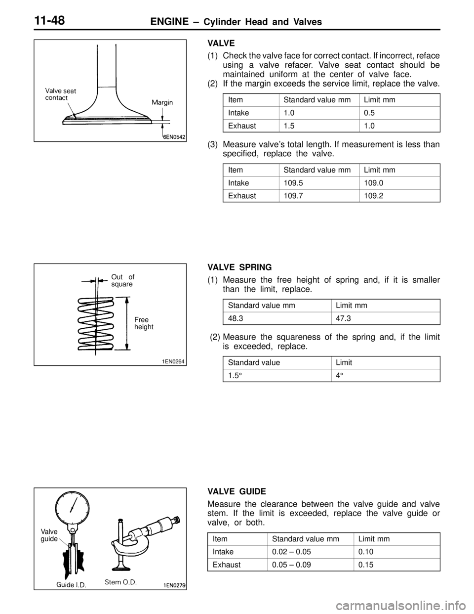
VA LV E
(1) Check the valve face for correct contact. If incorrect, reface
using a valve refacer. Valve seat contact should be
maintained uniform at the center of valve face.
(2) If the margin exceeds the service limit, replace the valve.
ItemStandard value mmLimit mm
Intake1.00.5
Exhaust1.51.0
(3) Measure valve’s total length. If measurement is less than
specified, replace the valve.
ItemStandard value mmLimit mm
Intake109.5109.0
Exhaust109.7109.2
VALVE SPRING
(1) Measure the free height of spring and, if it is smaller
than the limit, replace.
Standard value mmLimit mm
48.347.3
(2) Measure the squareness of the spring and, if the limit
is exceeded, replace.
Standard valueLimit
1.5°4°
VALVE GUIDE
Measure the clearance between the valve guide and valve
stem. If the limit is exceeded, replace the valve guide or
valve, or both.
ItemStandard value mmLimit mm
Intake0.02 – 0.050.10
Exhaust0.05 – 0.090.15
1EN0264
Free
height
Out of
square
Valve
guide
Page 75 of 558
ENGINE – Cylinder Head and Valves11-50
VALVE GUIDE REPLACEMENT PROCEDURE
(1) Force the valve guide out toward the cylinder block using
a press.
(2) Machine the valve guide hole in the cylinder head to
the size of the oversize valve guide to be installed.
Caution
Do not use the valve guide of the same size as the
removed one.
Valve gauge hole diameters in cylinder head
ItemStandard value mm
0.05 O.S.12.05 – 12.07
0.25 O.S.12.25 – 12.27
0.50 O.S.12.50 – 12.52
(3) Press-fit the valve guide until it protrude specified value
19.5 mm as shown in the illustration.
Caution
1. Press the valve guide from the cylinder head top
surface.
2. Valve guide for intake valve and that for exhaust
valve are different in length. (45.5 mm for intake
valve; 50.5 mm for exhaust valve)
(4) After the valve guide has been installed, insert a new
valve to check for smooth sliding motion.
1EN0106
Protrusion
Page 81 of 558

ENGINE – Front Case, Counterbalance Shaft and Oil Pan11-56
(2) Secure the oil pump driven gear onto the left
counterbalance shaft by tightening the flange bolt to
specified torque.
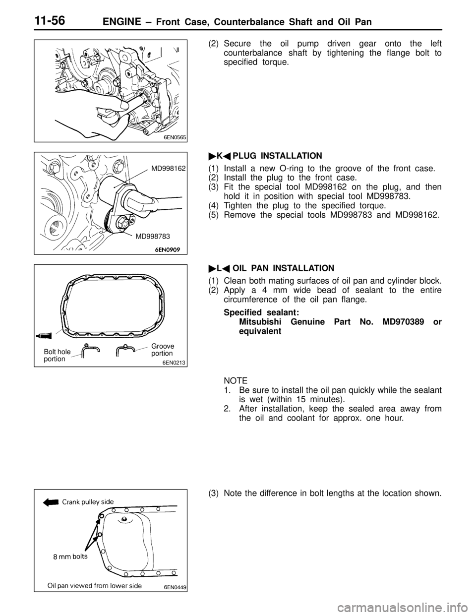
�K�PLUG INSTALLATION
(1) Install a new O-ring to the groove of the front case.
(2) Install the plug to the front case.
(3) Fit the special tool MD998162 on the plug, and then
hold it in position with special tool MD998783.
(4) Tighten the plug to the specified torque.
(5) Remove the special tools MD998783 and MD998162.
�L�OIL PAN INSTALLATION
(1) Clean both mating surfaces of oil pan and cylinder block.
(2) Apply a 4 mm wide bead of sealant to the entire
circumference of the oil pan flange.
Specified sealant:
Mitsubishi Genuine Part No. MD970389 or
equivalent
NOTE
1. Be sure to install the oil pan quickly while the sealant
is wet (within 15 minutes).
2. After installation, keep the sealed area away from
the oil and coolant for approx. one hour.
(3) Note the difference in bolt lengths at the location shown.
MD998162
MD998783
6EN0213
Bolt hole
portionGroove
portion
Page 86 of 558

ENGINE – Piston and Connecting Rod11-61
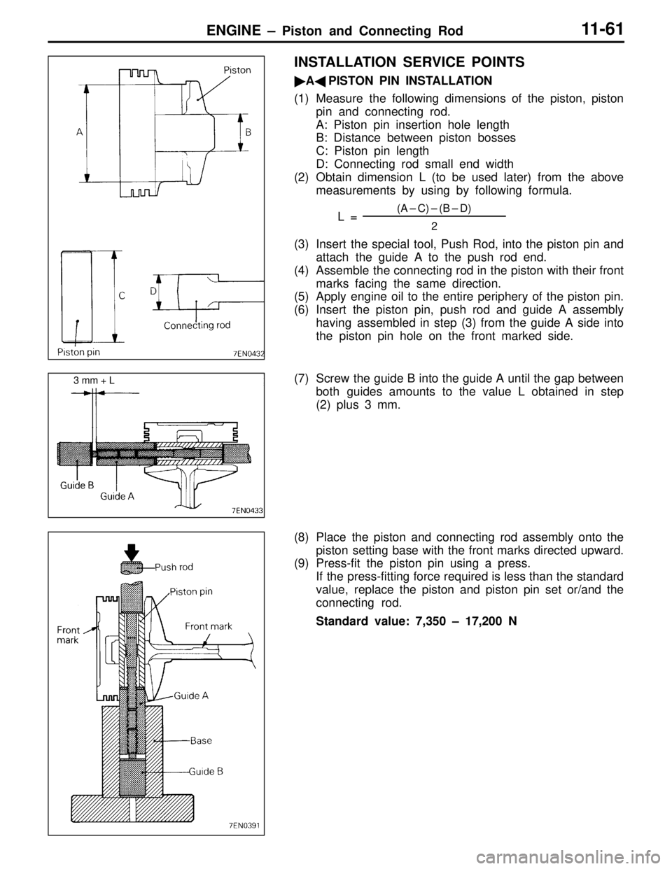
INSTALLATION SERVICE POINTS
�A�PISTON PIN INSTALLATION
(1) Measure the following dimensions of the piston, piston
pin and connecting rod.
A: Piston pin insertion hole length
B: Distance between piston bosses
C: Piston pin length
D: Connecting rod small end width
(2) Obtain dimension L (to be used later) from the above
measurements by using by following formula.
L =
(A – C) – (B – D)
2
(3) Insert the special tool, Push Rod, into the piston pin and
attach the guide A to the push rod end.
(4) Assemble the connecting rod in the piston with their front
marks facing the same direction.
(5) Apply engine oil to the entire periphery of the piston pin.
(6) Insert the piston pin, push rod and guide A assembly
having assembled in step (3) from the guide A side into
the piston pin hole on the front marked side.
(7) Screw the guide B into the guide A until the gap between
both guides amounts to the value L obtained in step
(2) plus 3 mm.
(8) Place the piston and connecting rod assembly onto the
piston setting base with the front marks directed upward.
(9) Press-fit the piston pin using a press.
If the press-fitting force required is less than the standard
value, replace the piston and piston pin set or/and the
connecting rod.
Standard value: 7,350 – 17,200 N
3 mm + L