Page 7 of 558

GENERAL – How to Use This Manual00-4
EXPLANATION OF MANUAL CONTENTS
Indicates procedures to be performed
before the work in that section is started,
and procedures to be performed after
the work in that section is finished.
Indicates (by symbols) where lubrica-
tion is necessary.
Maintenance and Servicing Procedures
The numbers provided within the diagram indi-
cate the sequence for maintenance and servic-
ing procedures.
�Removal steps:
The part designation number corresponds
to the number in the illustration to indicate
removal steps.
�Disassembly steps:
The part designation number corresponds
to the number in the illustration to indicate
disassembly steps.�Installation steps:
Specified in case installation is impossible
in reverse order of removal steps. Omitted
if installation is possible in reverse order of
removal steps.
�Reassembly steps:
Specified in case reassembly is impossible
in reverse order of disassembly steps.
Omitted if reassemby is possible in reverse
order of disassembly steps.
Classifications of Major Maintenance/Service Points
When there are major points relative to maintenance and servicing procedures
(such as essential maintenance and service points, maintenance and service stan-
dard values, information regarding the use of special tools, etc.), these are ar-
ranged together as major maintenance and service points and explained in detail.
�A�: Indicates that there are essential points for removal or disassembly.
�A�: Indicates that there are essential points for installation or reassembly.
Symbols for Lubrication, Sealants and Adhesives
Information concerning the locations for lubrica-
tion and for application of sealants and adhe-
sives is provided, by using symbols, in the dia-
gram of component parts or on the page follow-
ing the component parts page, and explained.: Grease
(multipurpose grease unless there is a
brand or type specified)
: Sealant or adhesive
: Brake fluid or automatic transmission fluid
: Engine oil, gear oil or air conditioner com-
pressor oil
: Adhesive tape or butyl rubber tape
Component Diagram
A diagram of the component parts is
provided near the front of each section
in order to give a reader a better under-
standing of the installed condition of
component parts.
Page 19 of 558

GENERAL – Precautions Before Service00-16
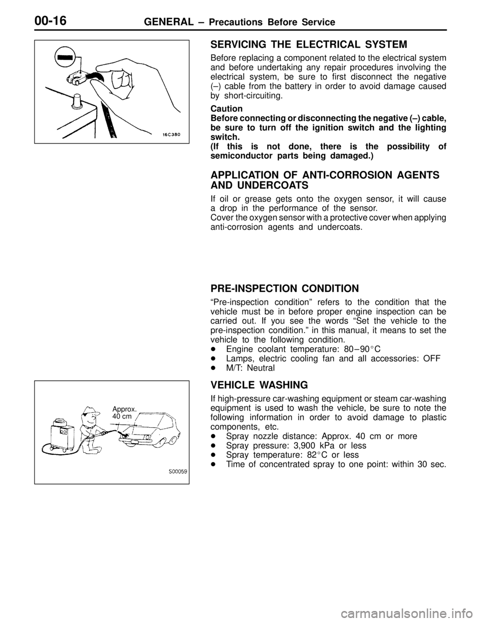
SERVICING THE ELECTRICAL SYSTEM
Before replacing a component related to the electrical system
and before undertaking any repair procedures involving the
electrical system, be sure to first disconnect the negative
(–) cable from the battery in order to avoid damage caused
by short-circuiting.
Caution
Before connecting or disconnecting the negative (–) cable,
be sure to turn off the ignition switch and the lighting
switch.
(If this is not done, there is the possibility of
semiconductor parts being damaged.)
APPLICATION OF ANTI-CORROSION AGENTS
AND UNDERCOATS
If oil or grease gets onto the oxygen sensor, it will cause
a drop in the performance of the sensor.
Cover the oxygen sensor with a protective cover when applying
anti-corrosion agents and undercoats.
PRE-INSPECTION CONDITION
“Pre-inspection condition” refers to the condition that the
vehicle must be in before proper engine inspection can be
carried out. If you see the words “Set the vehicle to the
pre-inspection condition.” in this manual, it means to set the
vehicle to the following condition.
�Engine coolant temperature: 80–90�C
�Lamps, electric cooling fan and all accessories: OFF
�M/T: Neutral
VEHICLE WASHING
If high-pressure car-washing equipment or steam car-washing
equipment is used to wash the vehicle, be sure to note the
following information in order to avoid damage to plastic
components, etc.
�Spray nozzle distance: Approx. 40 cm or more
�Spray pressure: 3,900 kPa or less
�Spray temperature: 82�C or less
�Time of concentrated spray to one point: within 30 sec.
Approx.
40 cm
Page 26 of 558

11-1
ENGINE
CONTENTS
GENERAL INFORMATION 2. . . . . . . . . . . . . . . .
SPECIFICATIONS 3. . . . . . . . . . . . . . . . . . . . . . . .
Service Specifications 3. . . . . . . . . . . . . . . . . . . . . .
Torque Specifications 5. . . . . . . . . . . . . . . . . . . . . .
New Tightening Method by Use of Bolts
to Be Tightened in Plastic Area 9. . . . . . . . . . . .
Sealants 9. . . . . . . . . . . . . . . . . . . . . . . . . . . . . . . . . .
Form-In-Place Gasket 10. . . . . . . . . . . . . . . . . . . .
SPECIAL TOOLS 11. . . . . . . . . . . . . . . . . . . . . . .
ALTERNATOR AND IGNITION SYSTEM 14.
TIMING BELT 15. . . . . . . . . . . . . . . . . . . . . . . . .
FUEL AND EMISSION CONTROL PARTS 27
SECONDARY AIR SYSTEM AND INTAKE
MANIFOLD 29. . . . . . . . . . . . . . . . . . . . . . . . . . . . EXHAUST MANIFOLD 31. . . . . . . . . . . . . . . . .
WATER PUMP AND WATER HOSE 34. . . . .
ROCKER ARMS AND CAMSHAFT 37. . . . . .
CYLINDER HEAD AND VALVES 43. . . . . . . .
FRONT CASE, COUNTERBALANCE
SHAFT AND OIL PAN 51. . . . . . . . . . . . . . . . .
PISTON AND CONNECTING ROD 59. . . . . .
CRANKSHAFT AND FLYWHEEL 67. . . . . . . .
THROTTLE BODY 73. . . . . . . . . . . . . . . . . . . . .
TURBOCHARGER 75. . . . . . . . . . . . . . . . . . . . .
ALTERNATOR 79. . . . . . . . . . . . . . . . . . . . . . . . .
STARTER MOTOR 83. . . . . . . . . . . . . . . . . . . . .
Page 27 of 558
ENGINE – General Information11-2
GENERAL INFORMATION
DescriptionsSpecifications
TypeIn-line OHV, SOHC
Number of cylinders4
Combustion chamberPentroof + curved top piston type
Total displacement dm31,997
Cylinder bore mm85.0
Piston stroke mm88.0
Compression ratio8.8
Valve timingIntake valveOpens (BTDC)21°
Closes (ABDC)59°
Exhaust valveOpens (BBDC)58°
Closes (ATDC)18°
Lubrication systemPressure feed, full-flow filtration
Oil pump typeInvolute gear type
Page 29 of 558

ENGINE – Specifications11-4
ItemsLimit Standard value
Intake oversize rework dimensions of valve
guide hole mm
0.3 O.S.35.30 – 35.33–
guide hole mm0.6 O.S.35.60 – 35.63–
Exhaust oversize rework dimensions of
valve guide hole mm
0.3 O.S.33.30 – 33.33–
valve guide hole mm0.6 O.S.33.60 – 33.63–
Front case and oil pan
Oil pump side clearance mmDrive gear0.08 – 0.14–
Driven gear0.06 – 0.12–
Oil pressure at curb idle speed kPa [Oil temperature is 75 to 90°C]78 or more–
Piston and connecting rod
Piston outer diameter mm85.0–
Piston ring side clearance mmNo. 1 ring0.04 – 0.075–
No. 2 ring0.02 – 0.06–
Piston ring end gap mmNo. 1 ring0.25 – 0.350.8
No. 2 ring0.40 – 0.550.8
Oil ring0.10 – 0.401.0
Piston pin outer diameter mm21.0–
Piston pin press-in load N (Room temperature)7,350 – 17,200–
Crankshaft pin oil clearance mm0.02 – 0.050.1
Connecting rod big end side clearance mm0.10 – 0.250.4
Crankshaft and flywheel
Crankshaft end play mm0.05 – 0.250.40
Crankshaft journal outer diameter mm57.0–
Crankshaft pin outer diameter mm44.0–
Crankshaft journal oil clearance mm0.02 – 0.040.1
Bearing cap bolt shank length mm–Maximum 71.1
Piston to cylinder clearance mm0.02 – 0.04–
Cylinder block grinding limit of gasket surface mm
Total resurfacing depth of both cylinder head and cylinder block–0.2
Cylinder block overall height mm284–
Cylinder block inner diameter mm85.0–
Cylinder block cylinder mm0.01–
Turbocharger
Waste gate actuator operation check kPa100113.3
Page 30 of 558
ENGINE – Specifications11-5
ItemsLimit Standard value
Alternator
Rotor coil resistance ΩApprox. 3 – 5–
Protrusion length of brush mm–2
Starter motor
Commutator runout mm0.050.1
Commutator outer diameter mm32.031.4
Commutator undercut mm0.5–
TORQUE SPECIFICATIONS
ItemsNm
Alternator and ignition system
Oil level gauge guide13
Water pump pulley9
Alternator brace (Alternator side)21
Alternator brace (Tightened with water pump)23
Alternator pivot bolt44
Crankshaft pulley25
Center cover3
Spark plug25
Ignition coil10
Timing belt
Timing belt cover (Flange bolt)11
Timing belt cover (Washer bolt)9
Power steering pump bracket49
Tensioner pulley49
Tensioner arm24
Auto tensioner24
Idler pulley48
Crank angle sensor9
Oil pump sprocket54
Camshaft bolt11 8
Tensioner “B”19
Counterbalance shaft sprocket45
Page 32 of 558

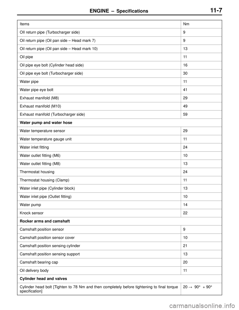
ENGINE – Specifications11-7
ItemsNm
OIl return pipe (Turbocharger side)9
Oil return pipe (Oil pan side – Head mark 7)9
Oil return pipe (Oil pan side – Head mark 10)13
Oil pipe11
Oil pipe eye bolt (Cylinder head side)16
Oil pipe eye bolt (Turbocharger side)30
Water pipe11
Water pipe eye bolt41
Exhaust manifold (M8)29
Exhaust manifold (M10)49
Exhaust manifold (Turbocharger side)59
Water pump and water hose
Water temperature sensor29
Water temperature gauge unit11
Water inlet fitting24
Water outlet fitting (M6)10
Water outlet fitting (M8)13
Thermostat housing24
Thermostat housing (Clamp)11
Water inlet pipe (Cylinder block)13
Water inlet pipe (Outlet fitting)10
Water pump14
Knock sensor22
Rocker arms and camshaft
Camshaft position sensor9
Camshaft position sensor cover10
Camshaft position sensing cylinder21
Camshaft position sensing support13
Camshaft bearing cap20
Oil delivery body11
Cylinder head and valves
Cylinder head bolt [Tighten to 78 Nm and then completely before tightening to final torque
specification]20� 90° + 90°
Page 33 of 558
ENGINE – Specifications11-8
ItemsNm
Front case and oil pan
Drain plug39
Oil pan7
Oil screen19
Buffle plate22
Oil pressure switch10
Oil cooler by-pass valve54
Relief plug44
Plug24
Front case24
Oil pump cover (Screw)10
Oil pump cover (Bolt)16
Piston and connecting rods
Connecting rod nut20 + 90° to 94°
Crankshaft and flywheel
Flywheel bolt132
Rear plate11
Bell housing cover9
Oil seal case11
Beam bearing cap bolt25 + 90°
Check valve32
Throttle body
Throttle position sensor3.5
Idle speed control body assembly3.5
Turbocharger
Waste gate actuator11