Page 114 of 558
MPI – General13-2
MULTIPOINT INJECTION (MPI)
GENERAL
OUTLINE OF CHANGE
�The descriptions of the troubleshooting using an MUT-II tester have been added.
�The fuel system and its management of EVOLUTION-VI are different from those of EVOLUTION-V
in the following items. Accordingly, the service procedures for these items are described herein. The
service procedures for the remaining item are the same as those for EVOLUTION-V.
�Fan motor control
�Fuel pump drive control
�Fuel pump relay No.2
�Fuel pump resistor
�Actuator test function of MUT-II (The test of the following items has been made possible.)
a) Item No.36: Secondary air control solenoid valve
b) Item No.37: Air conditioner condenser fan (High)
c) Item No.38: Air conditioner condenser fan (Low)
Page 136 of 558

MPI – Troubleshooting13-24
INSPECTION PROCEDURE 7
Long time to start (Improper starting)
Probable cause
In cases such as the above, the cause is probably that the spark is weak and ignition
is difficult, the initial mixture for starting is not appropriate, or sufficient compression
pressure is not being obtained.�Malfunction of the ignition system
�Malfunction of the injector system
�Inappropriate gasoline use
�Poor compression
Check system voltage when cranking
OK:8 V or higherNGCheck the battery.
OK
MUT-II: Check if uncomplete combustion occurs.
(Refer to P.13-48, INSPECTION PROCEDURE 39.)
OK
Can any sound be heard from the injectors when cranking (check
using a soundscope)?NGCheck the injector system. (Refer to P.13-15, INSPECTION PRO-
CEDURE FOR DIAGNOSIS CODE 41.)
OK
Check the ignition timing when cranking.
OK:Approx. 5�BTDCNGCheck that the crank angle sensor and the timing belt cover are
installed properly.
OK
Check the following items.
�Check the ignition coil, spark plugs, spark plug cables.
�Check the injectors for clogging and leakage.
�Check the compression pressure.
�Check if foreign materials (water, alcohol, etc.) got into fuel.
Page 173 of 558

MPI – Troubleshooting13-61
8. ACTUATOR TEST REFERENCE TABLE
Item
No.Inspection
itemDrive contentsInspection contentsNormal conditionInspection
procedure
No.Reference
page
01InjectorsCut fuel to No.
1 injectorEngine:
After having warmed
up/Engine is idling
Idling condition
becomes different
(becomes unsta
Code No.
4113-15
02Cut fuel to No.
2 injectorup/Engine is idling
(Cut the fuel supply to each
injector in turn and check
li d hi h d’ff
(becomes unsta-
ble, resulting in
engine stall).
03Cut fuel to No.
3 injector
j
cylinders which don’t affect
idling.)
04Cut fuel to No.
4 injector
07Fuel pumpFuel pump
operates and
fuel is recircu-
lated.�Engine:
Cranking
�Fuel
pump:
Forced
driving
Inspect ac-
cording to
Pinch the
return hose
with fingers
to feel the
pulse of the
fuel being
recirculated.Pulse is felt.Procedure
No. 2513-36
cording to
both the
above condi-
tions.
Listen near
the fuel tank
for the
sound of
fuel pump
operation.Sound of opera-
tion is heard.
09Fuel
pressure
control
valveSolenoid valve
turns from
OFF to ON.Ignition switch: ONSound of opera-
tion can be heard
when solenoid
valve is driven.Procedure
No. 3413-45
12Waste
gate
solenoid
valveSolenoid valve
turns from
OFF to ON.Ignition switch: ONSound of opera-
tion can be heard
when solenoid
valve is driven.Procedure
No. 3513-45
13Fuel pump
relay No.2Turn fuel
pump relay
No.2 from
OFF to ON.�Ignition switch: ON
�Listen to pump operation
sound near fuel tank.Sound of opera-
tion can be heard.Procedure
No. 2513-36
17Basic igni-
tion timingSet to ignition
timing adjust-
ment mode�Engine: Idling
�Timing light is set5�BTDC––
Page 197 of 558

27-1
REAR AXLE
CONTENTS
GENERAL 2. . . . . . . . . . . . . . . . . . . . . . . . . . . . . . .
Outline of Change 2. . . . . . . . . . . . . . . . . . . . . . . . .
SERVICE SPECIFICATIONS 2. . . . . . . . . . . . . .
LUBRICANT 2. . . . . . . . . . . . . . . . . . . . . . . . . . . . .
SPECIAL TOOLS 3. . . . . . . . . . . . . . . . . . . . . . . .
TROUBLESHOOTING 4. . . . . . . . . . . . .
ON-VEHICLE SERVICE
31. . . . . . . . . . . . . . .
Rear Axle Total Backlash Check 31. . . . . . . . . . .
Gear Oil Level Check 31. . . . . . . . . . . . . . . . . . . .
Gear Oil Change 32. . . . . . . . . . . . . . . . . . . . . . . . .
Fluid Level Check 33. . . . . . . . . . . . . . . . . . . . . . . . Bleeding 34. . . . . . . . . . . . . . . . . . . . . . . . . . . . . . . . .
AYC Operation Check 34. . . . . . . . . . . . . . . . . . . .
Hydraulic Pressure Check 35. . . . . . . . . . . . . . . . .
Differential Carrier Oil Seal
Replacement 36. . . . . . . . . . . . . . . . . . . . . . . . . . . . .
Wheel Speed Sensor Output Voltage
Measurement 37. . . . .
Action When Battery Runs Out 38. . . . . . . . . . . .
HYDRAULIC UNIT
39. . . . . . . . . . . . . . .
SENSOR RELAY
41. . . . . . . . . . . . . . .
AYC-ECU 42. . . . . . . . . . . . . . . . . . . . . . . . . . . . . .
Page 198 of 558
REAR AXLE – General / Service Specifications / Lubricant27-2
GENERAL
OUTLINE OF CHANGE
�The descriptions of the service procedures for the AYC system including the troubleshooting using
an MUT-II tester has been incorporated.
SERVICE SPECIFICATIONS
ItemsStandard valueLimit
Rear axle total backlash mm–5
Pressure generated by hydraulic unit MPa0 – 1.6–
Wheel bearing axial play mm–0.05
Wheel bearing rotation starting torque Nm–1.0 or less
LUBRICANT
ItemsSpecified lubricantCapacity
Gear oilTorque
transfer
differential
DifferentialHypoid gear oil API classification GL-5 or higher
SAE viscosity No. 90, 80W0.41 ± 0.02 �
differentialTorque transfer
mechanismMITSUBISHI GENUINE DIA QUEEN AYC FLUID0.70�0
�0.05�
Hydraulic piping fluidDia Queen ATF SPII or equivalent1 �
Torque transfer mechanism oil seal lipsVaselineAs required
Page 199 of 558
REAR AXLE – Special Tools27-3
SPECIAL TOOLS
ToolNumberNameUse
MB991502MUT-II sub-
assemblyInspection of AYC
(diagnosis display by MUT-II)
MB991529Diagnosis code
check harnessInspection of AYC
(diagnosis display by AYC warning lamp)
MD998330
(MD998331)Oil pressure
gauge
(2,942 kPa)Hydraulic pressure measurement
MB991705Hose adapter
MB990925Bearing & oil seal
installer setPressfitting of oil seal
MB991115Oil seal installerPressfitting of oil seal
(used in combination with MB990938)
MD998812Installer capPressfitting of oil seal
nism of vehicles with AYC>
MD998813Installer 100
MD998829Installer adapter
(60)
Page 219 of 558
REAR AXLE – Troubleshooting 27-23
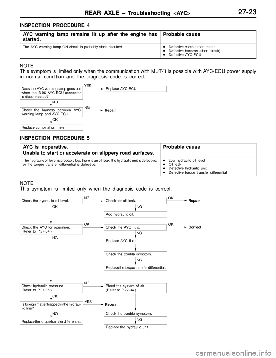
INSPECTION PROCEDURE 4
AYC warning lamp remains lit up after the engine has
started.
Probable cause
The AYC warning lamp ON circuit is probably short-circuited.�Defective combination meter
�Defective harness (short-circuit)
�Defective AYC-ECU
NOTE
This symptom is limited only when the communication with MUT-II is possible with AYC-ECU power supply
in normal condition and the diagnosis code is correct.
OK
Replace combination meter.
NO
Check the harness between AYC
warning lamp and AYC-ECU.NG
Repair
Does the AYC warning lamp goes out
when the B-96 AYC-ECU connector
is disconnected?YESReplace AYC-ECU.
INSPECTION PROCEDURE 5
AYC is inoperative.
Unable to start or accelerate on slippery road surfaces.
Probable cause
The hydraulic oil level is probably low, there is an oil leak, the hydraulic unit is defective,
or the torque transfer differential is defective.�Low hydraulic oil level
�Oil leak
�Defective hydraulic unit
�Defective torque transfer differential
NOTE
This symptom is limited only when the diagnosis code is correct.
NG
Replace the hydraulic unit.
NG
Replace the torque transfer differential.
Check the trouble symptom.
NG
Replace AYC fluid.
OK
Correct
Check the trouble symptom.NO
Replace the torque transfer differential.
OK
Is foreign matter trapped in the hydrau-
lic line?YES
Repair
OK
Check the AYC for operation.
(Refer to P.27-34.)OKCheck the AYC fluid.
NG
Add hydraulic oil.
NG
Check hydraulic pressure..
(Refer to P.27-35.)NGBleed the system of air.
(Refer to P.27-34.)
Check the hydraulic oil level.NGCheck for oil leak.OK
Repair
Page 220 of 558
REAR AXLE – Troubleshooting 27-24
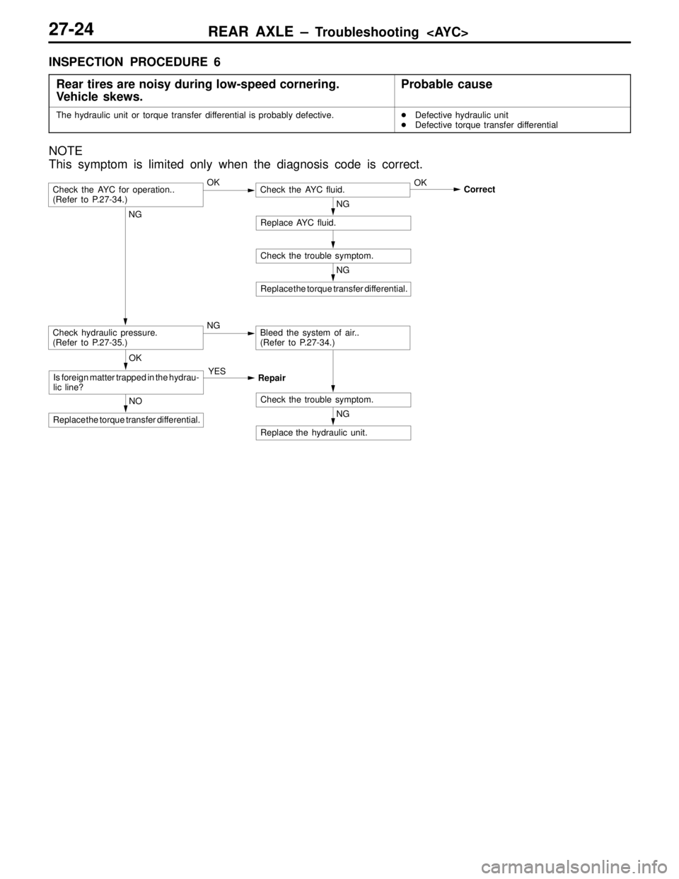
INSPECTION PROCEDURE 6
Rear tires are noisy during low-speed cornering.
Vehicle skews.
Probable cause
The hydraulic unit or torque transfer differential is probably defective.�Defective hydraulic unit
�Defective torque transfer differential
NOTE
This symptom is limited only when the diagnosis code is correct.
NG
Replace the hydraulic unit.
NG
Replace the torque transfer differential.
Check the trouble symptom.
NG
Replace AYC fluid.
OK
Correct
Check the trouble symptom.NO
Replace the torque transfer differential.
OK
Is foreign matter trapped in the hydrau-
lic line?YES
Repair
Check the AYC for operation..
(Refer to P.27-34.)OKCheck the AYC fluid.
NG
Check hydraulic pressure.
(Refer to P.27-35.)NGBleed the system of air..
(Refer to P.27-34.)