Page 30 of 558
ENGINE – Specifications11-5
ItemsLimit Standard value
Alternator
Rotor coil resistance ΩApprox. 3 – 5–
Protrusion length of brush mm–2
Starter motor
Commutator runout mm0.050.1
Commutator outer diameter mm32.031.4
Commutator undercut mm0.5–
TORQUE SPECIFICATIONS
ItemsNm
Alternator and ignition system
Oil level gauge guide13
Water pump pulley9
Alternator brace (Alternator side)21
Alternator brace (Tightened with water pump)23
Alternator pivot bolt44
Crankshaft pulley25
Center cover3
Spark plug25
Ignition coil10
Timing belt
Timing belt cover (Flange bolt)11
Timing belt cover (Washer bolt)9
Power steering pump bracket49
Tensioner pulley49
Tensioner arm24
Auto tensioner24
Idler pulley48
Crank angle sensor9
Oil pump sprocket54
Camshaft bolt11 8
Tensioner “B”19
Counterbalance shaft sprocket45
Page 31 of 558
ENGINE – Specifications11-6
ItemsNm
Rocker cover3.5
Engine support bracket49
Camshaft sprocket bolt88
Timing belt rear right cover11
Timing belt rear left upper cover11
Fuel and emission control parts
Throttle body18
Fuel pressure regulator9
Delivery pipe11
Vacuum tank bracket9
Solenoid valve bracket9
Solenoid valve9
Vacuum hose and vacuum pipe11
Secondary air intake manifold
Heat protector13
Vacuum hose and vacuum pipe11
Air pipe (Heat protector side)13
Air pipe (Cam position sensor side)11
Air pipe (Eye bolt)49
Air pipe (Control valve side)24
Air control valve21
Air control valve bracket24
Intake manifold stay30
Intake manifold (M8)19
Intake manifold (M10)35
Exhaust manifold
Engine hanger12
Heat protector (Turbocharger side)14
Oxygen sensor54
Exhaust fitting bolt59
Exhaust fitting nut59
Air outlet fitting19
Page 32 of 558

ENGINE – Specifications11-7
ItemsNm
OIl return pipe (Turbocharger side)9
Oil return pipe (Oil pan side – Head mark 7)9
Oil return pipe (Oil pan side – Head mark 10)13
Oil pipe11
Oil pipe eye bolt (Cylinder head side)16
Oil pipe eye bolt (Turbocharger side)30
Water pipe11
Water pipe eye bolt41
Exhaust manifold (M8)29
Exhaust manifold (M10)49
Exhaust manifold (Turbocharger side)59
Water pump and water hose
Water temperature sensor29
Water temperature gauge unit11
Water inlet fitting24
Water outlet fitting (M6)10
Water outlet fitting (M8)13
Thermostat housing24
Thermostat housing (Clamp)11
Water inlet pipe (Cylinder block)13
Water inlet pipe (Outlet fitting)10
Water pump14
Knock sensor22
Rocker arms and camshaft
Camshaft position sensor9
Camshaft position sensor cover10
Camshaft position sensing cylinder21
Camshaft position sensing support13
Camshaft bearing cap20
Oil delivery body11
Cylinder head and valves
Cylinder head bolt [Tighten to 78 Nm and then completely before tightening to final torque
specification]20� 90° + 90°
Page 40 of 558

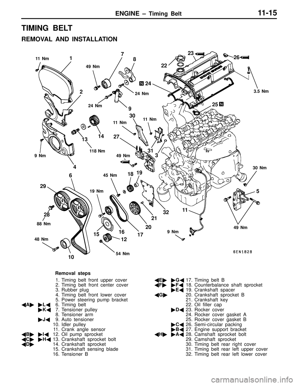
ENGINE – Timing Belt11-15
TIMING BELT
REMOVAL AND INSTALLATION
1
2
3
4
5 67
8
9
1011
12 1314
1516
17 1819
20212223
24
2526
27
28 2930
31
32
9 Nm
9 Nm 49 Nm 11 N m
11 N m
19 Nm 3.5 Nm
30 Nm
45 Nm 49 Nm 11 8 N m
88 Nm
48 Nm 49 Nm 11 N m
24 Nm
24 Nm
54 Nm
Removal steps
1. Timing belt front upper cover
2. Timing belt front center cover
3. Rubber plug
4. Timing belt front lower cover
5. Power steering pump bracket
�A��L�6. Timing belt
�K�7. Tensioner pulley
8. Tensioner arm
�J�9. Auto tensioner
10. Idler pulley
11. Crank angle sensor
�B��I�12. Oil pump sprocket
�C��H�13. Crankshaft sprocket bolt
�D�14. Crankshaft sprocket
15. Crankshaft sensing blade
16. Tensioner B�E��G�17. Timing belt B
�F��F�18. Counterbalance shaft sprocket
�E�19. Crankshaft spacer
�G�20. Crankshaft sprocket B
21. Crankshaft key
22. Oil filler cap
�D�23. Rocker cover
24. Rocker cover gasket A
25. Rocker cover gasket B
�C�26. Semi-circular packing
�B�27. Engine support bracket
�H��A�28. Camshaft sprocket bolt
29. Camshaft sprocket
30. Timing belt rear right cover
31. Timing belt rear left upper cover
32. Timing belt rear left lower cover
Page 62 of 558
ENGINE – Rocker Arms and Camshaft11-37
ROCKER ARMS AND CAMSHAFT
REMOVAL AND INSTALLATION
1 2 3
4
5 6
78
9
1011
121314
15
16
1718
11 Nm9 Nm 10 Nm
13 Nm 21 Nm
20 Nm
Apply engine oil to all
moving parts before
installation.
Removal steps
1. Cam position sensor
2. O-ring
3. Cam position sensor support cover
4. Cam position sensor support
gasket
�F�5. Cam position sensing cylinder
�E�6. Cam position sensor support
�D�7. Camshaft oil seal
�C�8. Camshaft bearing cap rear right
�C�9. Camshaft bearing cap rear left�C�10. Camshaft bearing cap front
�C�11. Camshaft bearing cap No. 5
�C�12. Camshaft bearing cap No. 2
�C�13. Camshaft bearing cap No. 3
�C�14. Camshaft bearing cap No. 4
�B�15. Camshaft
16. Rocker arm
�A�17. Lash adjuster
18. Oil delivery body
Page 63 of 558

ENGINE – Rocker Arms and Camshaft11-38
INSTALLATION SERVICE POINTS
�A�LASH ADJUSTER INSTALLATION
Caution
If the lash adjuster is re-used, clean the lash adjuster.
Fit the lash adjuster onto rocker arm without allowing diesel
fuel to spill out.
�B�CAMSHAFT INSTALLATION
(1) Apply engine oil to the journals and cams of the camshafts.
Install the camshafts on the cylinder head.
Use care not to confuse the intake camshaft with the
exhaust one. The intake camshaft has a slit on its rear
end for driving the crankshaft position sensor.
(2) Install the crankshaft sprocket B or spacer and flange
to one end of the crankshaft, and turn the crankshaft
until the timing marks are lined up, setting No. 1 cylinder
to the TDC.
(3) Set the camshafts so that their dowel pins are positioned
at top.
�C�BEARING CAP INSTALLATION
(1) According to the identification mark stamped on the top
of each bearing cap, install the caps to the cylinder head.
Only “L” or “R” is stamped on front bearing cap. Cap
No. is stamped on No. 2 to No. 5 bearing caps. Rear
bearing cap has no stamping.
I: For intake camshaft side
E: For exhaust camshaft side
(2) Tighten the bearing caps in the order shown two to three
times by torquing progressively.
Tighten to the specification in the final sequence.
(3) Check to ensure that the rocker arm is positioned correctly
on the lash adjuster and valve stem end.
Camshaft sprocket side
Slit
Intake side
camshaft
Dowel pin
Cam number
Symbol identifying
intake or exhaust
Timing belt side
Page 64 of 558

ENGINE – Rocker Arms and Camshaft11-39
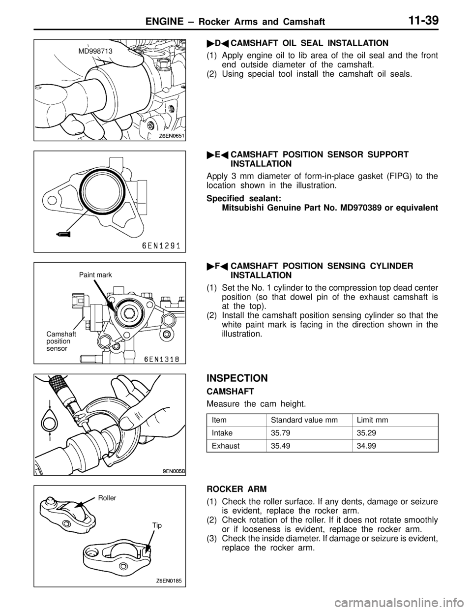
�D�CAMSHAFT OIL SEAL INSTALLATION
(1) Apply engine oil to lib area of the oil seal and the front
end outside diameter of the camshaft.
(2) Using special tool install the camshaft oil seals.
�E�CAMSHAFT POSITION SENSOR SUPPORT
INSTALLATION
Apply 3 mm diameter of form-in-place gasket (FIPG) to the
location shown in the illustration.
Specified sealant:
Mitsubishi Genuine Part No. MD970389 or equivalent
�F�CAMSHAFT POSITION SENSING CYLINDER
INSTALLATION
(1) Set the No. 1 cylinder to the compression top dead center
position (so that dowel pin of the exhaust camshaft is
at the top).
(2) Install the camshaft position sensing cylinder so that the
white paint mark is facing in the direction shown in the
illustration.
INSPECTION
CAMSHAFT
Measure the cam height.
ItemStandard value mmLimit mm
Intake35.7935.29
Exhaust35.4934.99
ROCKER ARM
(1) Check the roller surface. If any dents, damage or seizure
is evident, replace the rocker arm.
(2) Check rotation of the roller. If it does not rotate smoothly
or if looseness is evident, replace the rocker arm.
(3) Check the inside diameter. If damage or seizure is evident,
replace the rocker arm.
MD998713
Camshaft
position
sensorPaint mark
Roller
Tip
Page 115 of 558

MPI – General13-3
MPI System Diagram
�1 Injector
�2 ISC servo
�3 Fuel pressure control valve
�4 Waste gate solenoid valve
�5 Secondary air control solenoid valve
�Control relay
�Fuel pump relay
�A/C relay
�Ignition coil
�Exhaust temperature warning lamp
�Engine warning lamp
�Diagnosis output
�Alternator G terminal
�Fan motor relay
�Tachometer
�Fuel pump relay No.2 �1 Oxygen sensor
�2 Air flow sensor
�3 Intake air temperature sensor
�4 Throttle position sensor
�5 Idle switch
�6 Camshaft position sensor
�7 Crank angle sensor
�8 Barometric pressure sensor
�9 High temperature sensor
�10 Engine coolant temperature sensor
�11 Detonation sensor
�Power supply voltage
�Ignition switch-IG
�Ignition switch-ST
�Vehicle speed sensor
�A/C switch
�Power steering fluid pressure switch
�Alternator FR signalEngine ECU
�1 Oxygen sensor
�2 Air flow sensor�3
Intake air tem-
perature sensor
�4,
�5
�6 Camshaft position
sensor
�7 Crank angle sensor �8 Barometric
pressure sensor
�9 High temperature
sensor �10 Coolant temperature sensor
�11 Detonation sensor�1 Injector �2 ISC servo
�3 Fuel pressure
control valve
�4 Waste gate
solenoid valve �5 Secondary air
control solenoid
valveCanister
Check valveFrom
fuel
tank
Throttle position
sensor (with a
built-in
idle
switch)
Secondary
air valve
AirTo fuel
tankFuel
pressure
regulatorFrom
fuel
pump
Waste gate
actuator
Catalytic converter