Page 1244 of 2189
Doors
Door Index
2DI3D:
OU?ERWEATHERSIRIP
GLASS GUIDECLIP
I sAsH
€*/
.u\
\Y\I
et'
SPEAKER COVER
INNER HANDLE
ii MTRROR MOUNT<]<-- COVER PANEL
-it v
$=-!xtruce
re
(sqjR5f"'
@." \s-l
h-P
-Qa,
(l+,
@
TRIM(with power door locks)
eowen ooon
rocK swrrcH
\b
INNEF HANOLETRIM{without power
dD door locks)
DOORAdjustment,page 20-23
BRACKET
dl
h
W/
ARMRESTPOCKET
;ril;"i-"- 9
JE
powen____-.-@
wtNDow .*\L'l
swrrcH
t
-p
Q*-BsfL-,"ARMRESTPOCKETlwith power
PLASTICCOVER
,",
S
dnJ.*-{
r-1*{
,P
SPEAKER
20-14
Page 1260 of 2189

Windshield
Installation (cont'd)
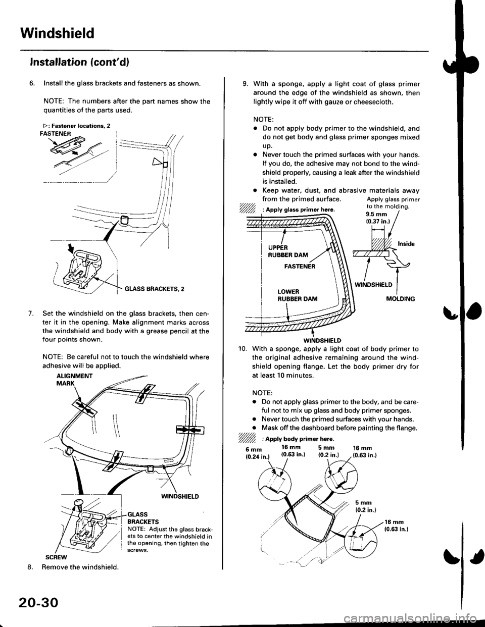
Installthe glass brackets and fasteners as shown.
NOTE: The numbers after the part names show thequantities of the oarts used.
GLASS BRACKETS, 2
Set the windshield on the glass brackets, then cen-
ter it in the opening. Make alignment marks across
the windshield and body with a grease pencil at the
four points shown.
NOTE: Be careful not to touch the windshield where
adhesive will be aDolied.
7.
8. Remove the windshield.
20-30
>: Fastoner locations, 2FASTENER ^ I
I
SCREW
9. With a sponge, apply a light coat of glass primer
around the edge of the windshield as shown. then
lightly wipe it off with gauze or cheesecloth.
NOTE:
. Do not apply body primer to the windshield. and
do not get body and glass primer sponges mixed
up.
. Never touch the primed surfaces with your hands.
lf you do. the adhesive may not bond to the wind-
shield properly, causing a leak after the windshield
is installed.
. Keep water. dust, and abrasrve
from the primed surface.t/////,'/////l I Apply glass p.imer here.
materaals away
Apply glass primerto the molding.
WINDSHIELD
10. With a sponge. apply a light coat of body primer to
the original adhesive remaining around the wind-
shield opening flange. Let the body primer dry for
at least 10 minutes.
NOTE:
. Do not apply glass primer to the body, and be care-
ful not to mix up glass and body primer sponges.
. Never touch the primed surfaces with your hands.
. Mask off the dashboard before painting the flange.7////l/////l I Apply body p mer hcre.
6mm16mm 5mm(0.6:| in.) (0.2 in.l16 mm
{0,63 in.}
/
MOLDING
Page 1281 of 2189

Troubleshooting
SymptomProbable Cause
Water leaks1. Clogged drain tube.
2. Gap between glass weatherstrjp and roof panel.
3. Defective or improperly installed glass weatherstrip.
4. Gap between drain seal and roof panel.
Wind noise'1. Excessive clearance between glass weatherstrip and roof panel.
Motor noise1. Loose motor.
2. Worn gear or bearing.
3. Cable assembly deformed.
Glass does not move, but motor turns'1. Clutch out of adjustment.
2. Foreign matter stuck between guide rail and slider.
3. lnner cable loose.
4. Cable assembly not attached properly.
Glass does not move and motor does not turn
{glass can be moved with moonroof wrench)
1. Blown fuse,
2. Faulty switch.
3. Battery run down.
4. Defective motor.
5. Faulty relay.
D
Glass Height Adjustment
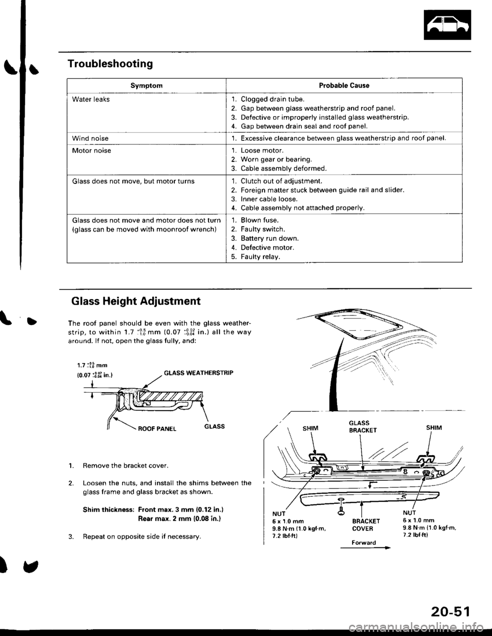
The roof panel should be even with the glass weather-
strip, to within 1.7 :lr3 mm (0.07 :3:31 in.) all the way
around. lf not, open the giass fully, and:
GLASS WEATHERSTRIP
1. Remove the bracket cover.
Loosen the nuts, and install the shims between the
glass frame and glass bracket as shown.
Shim thickness: Front max.3 mm 10,12 in.l
Rear max. 2 mm 10.08 in.)
Repeat on opposite side i{ necessary.
)
5x1.0mm9.8 N.m 11.0 kgf m,7.2 rbtft)
SRACKETCOVEB
----------1>
6x1.0mm9.8 N.m {1.0 kgtm,7.2 tbf.ft)
1.7 tl.8 mm
{0.07 :3 3i in.}
20-51
Page 1282 of 2189
Moonroof
Glass, Glass Bracket and Sunshade Replacement
l. Close the glass fully.
2. Slide the sunshade all the way back.
3. Remove both bracket covers.
Forward_--____->
4. Remove the nuts from both glass brackets.
6x1.0mm9.8 N.m (1.0 kgf.m,7.2lbt.ftl
Remove the glass by lifting up and pulling forward
as shown.
NOTE: Do not damage the roof panet.
ERACKET COVER
GLASS EBACKET
GLASS
\
20-52
DRAIN CHANNEL
6. Remove the drain channel.
7. Remove the holder cover. then remove the
holder B.
NUT6x1.0mm9 N.m {0.9 kgf.m.? tbtftl{i;t'm
RAIL HOLDER B
Using the moonroof wrench, move the glass bracket
to the position where the moonroof normally pivots
down, and remove the screws.
scREws
Page 1283 of 2189
b
D
9. Remove the rail holder A.
GLASS BRACKET
DRAIN CHANNEL ROO STOPRotate as shown to remove it from the guide rail.
10. Remove the drain channel rod slider by moving the
cable slider forward using the moonroof wrench.
'11. Detach the drain channel rod stop from the cutout
of the guide rail as shown.
DRAIN CHANNELROD
I
NUT6x1.0mmI N.m (0.9 kgf.m,SUNSHAOE
\
'14.
12. Slide the sunshade forward, then remove it.
Installation is the reverse of the removal procedure.
NOTE: Check the glass height (see page 20-51).
Check for water leaks,
NOTE: Do not use high-pressure water.
20-53
Page 1285 of 2189

L
L
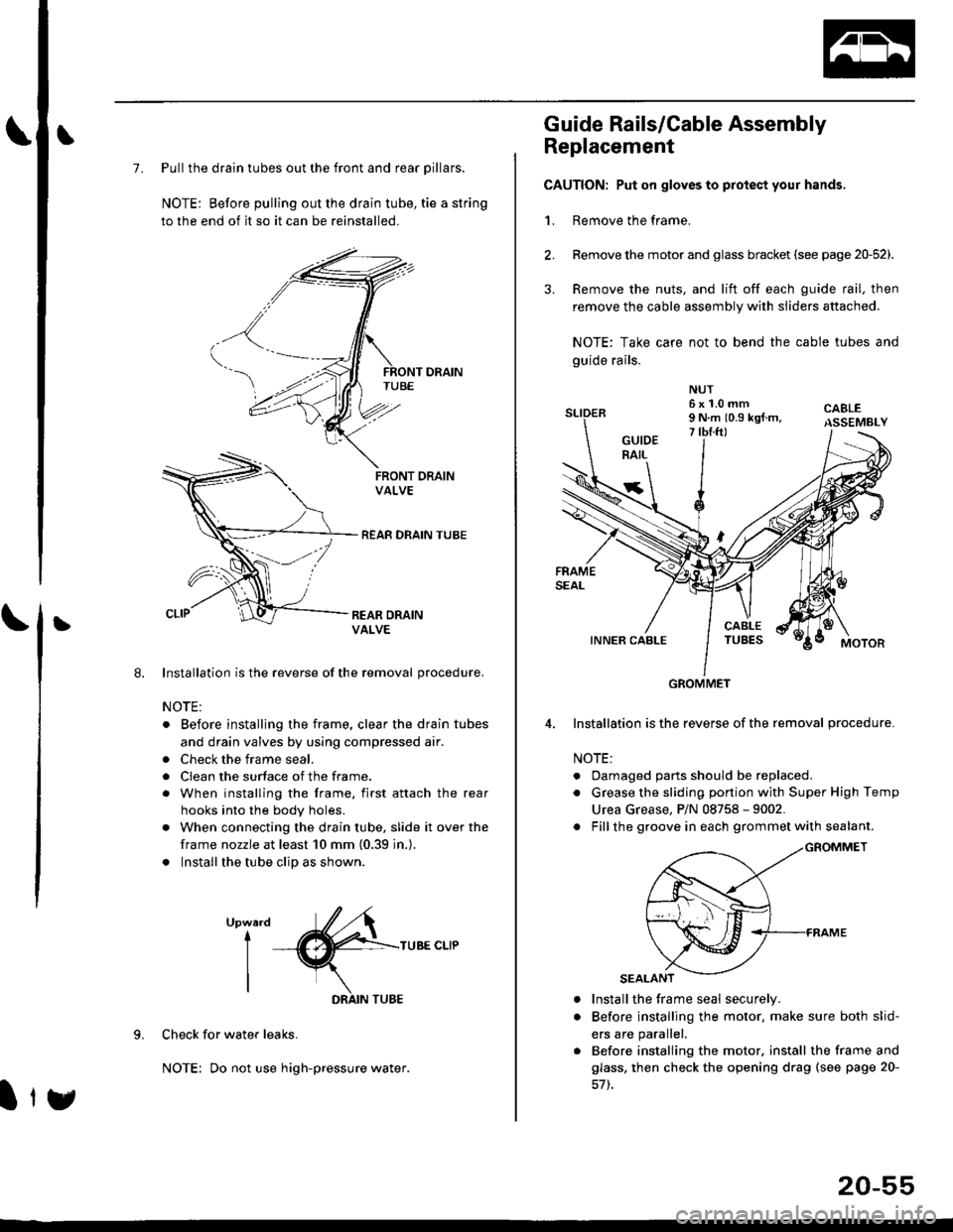
7. Pull the drain tubes out the front and rear pillars.
NOTE: Before pulling out the drain tube, tie a string
to the end of it so it can be reinstalled.
Installation is the reverse of the removal procedure.
NOTE:
. Before installjng the frame, clear the drain tubes
and drain valves by using compressed air.
. Check the frame seal.
. Clean the surface of the frame.
. When installing the frame, first attach the rear
hooks into the body holes.
. When connecting the drain tube, slide it over the
frame nozzle at least 10 mm (0.39 in.).
. Install the tube clip as shown.
UpwardI
I
I
TUBE CLIP
Check for water leaks.
NOTE: Do not use high-pressure water.
DRAIN TUBE
Ity
20-55
Guide Rails/Cable Assembly
Replacement
CAUTION: Put on gloves to protect your hands,
1. Remove the frame.
Remove the motor and glass bracket (see page 20-52).
Remove the nuts, and lift off each guide rail, then
remove the cable assembly with sliders attached.
NOTE: Take care not to bend the cable tubes and
guide rails.
Installation is the reverse of the removal procedure.
NOTE:
. Oamaged parts should be replaced.
. Grease the sliding portion with Super High Temp
Urea Grease, P/N 08758 - 9002.
. Fillthe groove in each grommet with sealant.
a
a
Install the frame seal securely.
Before installing the motor. make sure both slid-
ers are parallel.
Before installing the motor. install the frame and
glass, then check the opening drag (see page 20-
GROMMET
Page 1286 of 2189
Moonroof
1.
2.
Switch Plate Adjustment (Fully Closed Positionl
3.
4.
5.
Remove the headliner {see page 20-64).
Using the moonroof wrench, close the glass fully.
NOTE: Check the glass fit to the rool panel.
Using an open-end wrench, loosen the switch plate mounting bolts.
Adjust position of the switch plate (switch cam) as shown.
Check the operation of the glass (from tilt-up position to fully closed position, from the fully open position to the fully
closed position) by operating the moonroof switch.
NOTE: Check the glass height (see page 20-51).SWITCH PLATE
GUIDEPLATE
SWITCH CAM
While moving the switch plateplate at the position where thea (a faint click is heard).
INNER CABLE END
little bv little, secure the switchswitch cam contacts the switch
Close the glass fully, and check for water leaks.
NOTE: Do not use high-pressure water.
CAELE BRACKET
20-56
Page 1290 of 2189
lnterior Trim
Replacement (cont'dl
3D:
>: Clip locationsA>,2CLIP
N;
nt-.l I'"'\R
I
")!
F >, lil
TRIM
B>,3
G >,2H>,2
t
FRONT SEATBELT UPPEBANCHORlsee page 20 86)
SIDE TRIM PANELPROTECTOR
LEFT KICKPANEL
c >,8o>,3
PIVOT BRACKET
{see page 20-80)
lnstallation is the reverse of the removal procedure
NOTE:
. lf necessary, replace any damaged clips'
. Before installing the anchor bolts, make sure there
are no tlvists or kinks in the seat belts'
E >,8
>: Screw, bolt locationsA>,3 8>,6
^l l-lEF\
#, A@ Y
*"0
c>, 1
I "4"
\s
o >,2
l@@
\---
s,4, ffi;T
FRONT PILLARB
eV
REAR SIDESHELF
SIDE TRIMPANELRemove the rear seat-back and
rear seat cushion (see Page 20_80)
Disconnect the rear speaker
connector (both sides,
for some models).
REAR TRIMPANEL
q
RIGHT KICKPANEL
"x-
20-60