1999 HONDA CIVIC bracket
[x] Cancel search: bracketPage 1358 of 2189
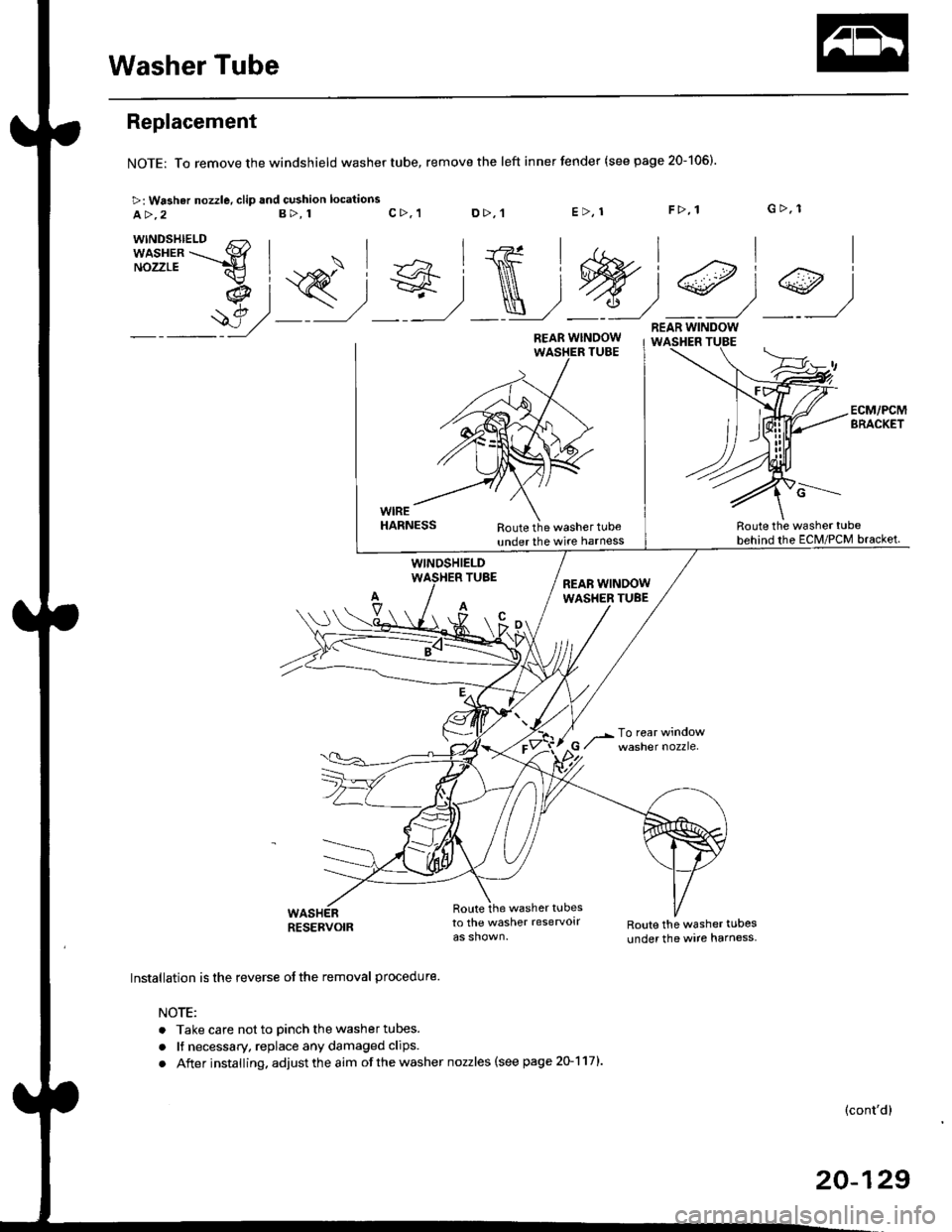
Washer Tube
Replacement
NOTE: To remove the windshield washer tube,
>: Washar nozzle, clip and cushion locations
a>,2B>, 1
remove the left inner fender (see page 20-106).
c>, 1 D>,'tE>, 1F>, 1 G>, 1
n,i#,T
I
9)
ECM/PCMBRACKET
WIREHARNESS
WINOSHIELDTUBE
A
Route the washer tubeunder the wire harnessRoute the washer tube
behind the EcM/PcM bracket.
(cont'd)
RESERVOIR
\/
Route the washer tubesto the washer reservolrRoute the washer tubes
under the wire harness.
Installation is the reverse of the removal procedure.
NOTE:
. Take care not to Dinch the washer tubes.
. lf necessary, replace any damaged clips.
. After installing, adjust the aim of the washer nozzles (see page 20-117l'
c-------.-
REAR WINDOWWASHER TUBE
20-129
Page 1447 of 2189
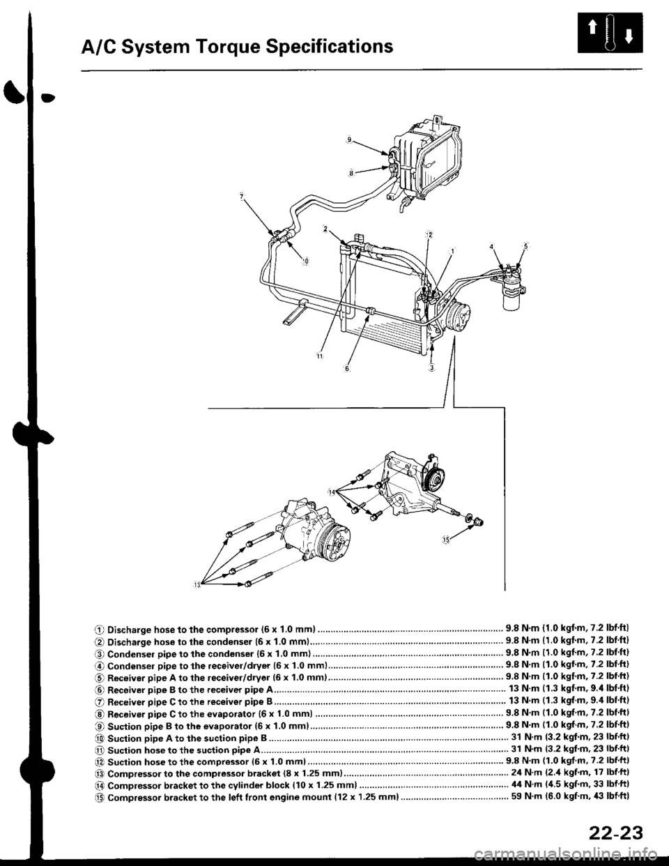
A/C System Torque Specifications
O Discharge hose to the compressor (6 x 1.0 mml ............... .. .... ...............' 9.8 N'm {1.0 kgf'm,7.2 lbf'ftl
@ Discharge hose to the condenser {6 x 1.0 mm1................... '... ...... . ......... 9.8 N'm 11.0 kgf'm, 7.2 lbf'ft}
O Condenser pipe to the condenser 16 x 1,0 mm)...............'. . . . ...........'..... 9.8 N'm (1.0 kgl'm, 7.2 lbt'ft)
@ Condensel pipe to the receivel/dryer (5 x 1.0 mml......... ..... . ... . '.......... 9.8 N'm (1.0 kgl'm, 7.2 lbt'ft)
O Receiver pipe A to the leceiver/dryer {6 x 1.0 mm)......... ... .......... .. . . .... 9.8 N'm 11.0 kgf'm. 7.2 lbl'ft)
@ Receiver pipe B to the receiver pipe A 13 N m (1.3 kgf'm, 9.'l lbf'ft)
O Receiver pipe C to the receiver pipe B 13 N m (1.3 kgf'm, 9.4 lbnftl
@ Receiver pipe C to the evaporator {6 x 1.0 mm) ....... 9.8 N'm (1.0 kgf'm, 7.2 lbtftl
O Suction pipe B to the evaporator (6 x 1.0 mml................ . .........'......'....... 9.8 N'm (1.0 kgf m, 7.2 lbf'ftl
e0 Suction pipe A to the suction pipe B ...'. . ...... . ... ...... 31 N'm (3.2 kgt'm, 23 lbf'ftl
O Suction hose to the suction pipe A... ............ . . '......... 31 N'm (3.2 kgl'm, 23 lbf'ft|
@ Suction hose to the compressor (6 x 1.0 mm)................... .. . ... .. ............ 9.8 N'm (1.0 kgf'm' 7.2 lbf'ft|
@@ Compressor to the compressor bracket (8 x 1.25 mm)... ..-........'.'......-.......24 N'm (2 'l kgf'm, 17 lbf ftl
@ Compressor bracket to the cytinder block (10 x 1.25 mml 44 N'm l'1.5 kgf'm, 33 lbf ftl
@ Compressor bracket to the left front engine mounl {12 x 1.25 mm}..... . . . . .. ................. ... ... 59 N'm (6.0 kgf'm, '|i} lbf ftl
22-23
Page 1455 of 2189
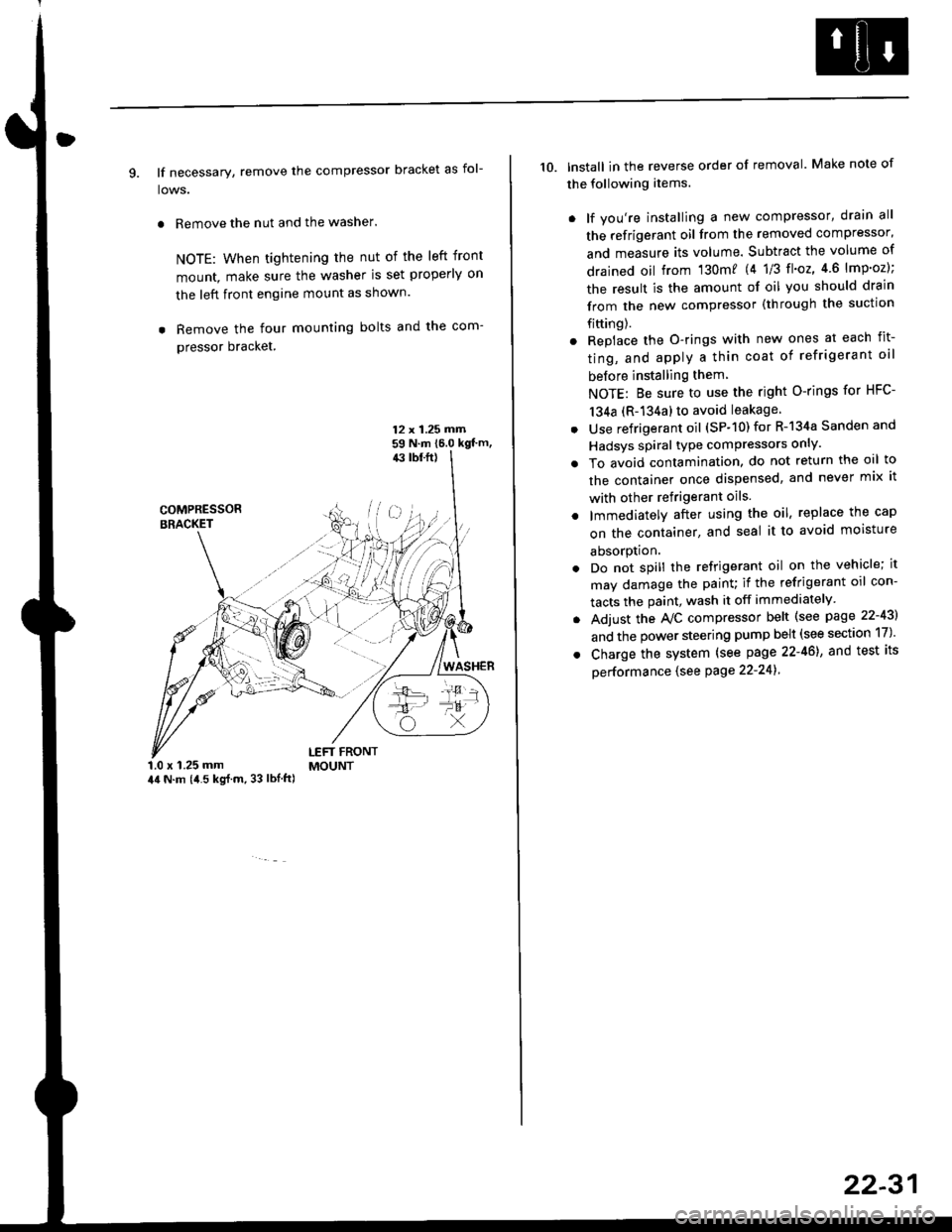
9. lf necessary, remove the compressor bracket as fol-
lows.
. Remove the nut and the washer.
NOTE: When tightening the nut of the left front
mount, make sure the washer is set properly on
the left front engine mount as shown.
. Remove the four mounting bolts and the com-
pressor bracket.
12 x 1.25 rrirn59 N.m 16.0 kgt'm,43 tbf.ft)
COMPRESSORBRACKET
WASHER
1.0 x 1.25 mm44 N.m (i1.5 kg{.m, 33 lbl.ft)
LEFT FRONTMOUNT
10. lnstall in the reverse order of removal. Make note of
the following items.
. lf you're installing a new compressor, drain all
the refrigerant oil from the removed compressor,
and measure its volume. Subtract the volume of
drained oil from '130m? 14 1/3 tl'o2,4 6 lmp'oz);
the result is the amount of oil you should drain
from the new compressor (through the suction
fifting).
. Replace the O-rings with new ones at each fit-
ting, and apply a thin coat of refrigerant oil
before installing them
NOTE: Be sure to use the right O-rings for HFC-
134a (R-134a) to avoid leakage
. Use refrigerant oil (SP-10) for R-134a Sanden and
Hadsys spiral type compressors only'
o To avoid contamination, do not return the oil to
the container once dispensed, and never mix it
with other refrigerant oils.
. lmmediatelY after using the oil, replace the cap
on the container, and seal it to avoid moisture
absorption.
. Do not spill the refrigerant oil on the vehicle; it
may damage the painu if the refrigerant oil con-
tacts the paint, wash it off immediately
. Adjust the Ay'C compressor belt (see page 22-43)
and the power steering pump belt (see section 17)'
. Charge the system (see page 22-46), and test its
oerformance (see Page 22-241
22-31
Page 1461 of 2189
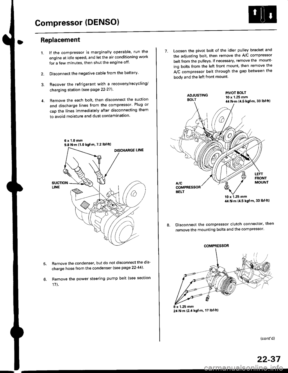
Compressor (DENSO)
Replacement
1.lf the compressor is marginally operable, run the
engine at idle speed, and let the air conditioning work
for a few minutes, then shut the engine off
Disconnect the negative cable from the battery'
Recover the refrigerant with a recovery/recycling/
charging station lsee page 22-271
Remove the each bolt, then disconnect the suction
and discharge lines from the compressor' Plug or
cap the lines immediately after disconnecting them
to avoid moisture and dust contaminatlon.
6 x '1.0 mm9.8 N.m (1.0 kgf m,7.2 lbfft)
Remove the condenser, but do not disconnect the dis-
charge hose from the condenser (see page 22-441'
Remove the power steering pump belt (see sectron
17]-.
7. Loosen the pivot bolt of the idler pulley bracket and
the adjusting bolt. then remove the A,/C compressor
belt from the pulleys. lf necessary, remove the mount-
ing bolts from the left front mount. then remove the
fuC compressor belt through the gap between the
bodv and the left front mount.
'10 x 1,25 mm4,0 N.m (,1.5 kgf'm. 33 lbt ftl
Disconnect the compressor clutch connector, then
remove the mounting bolts and the compressor'
PIVOT BOLT10 x 1.25 mm4,1 N.m (4.5 kgt'm,33 lbfft)
COMPRESSOR
24 N.m (2.4 kgf m, 17 lbf ftl
(cont'd)
22-37
Page 1462 of 2189
Compressor (DENSOI
Replacement (cont'd)
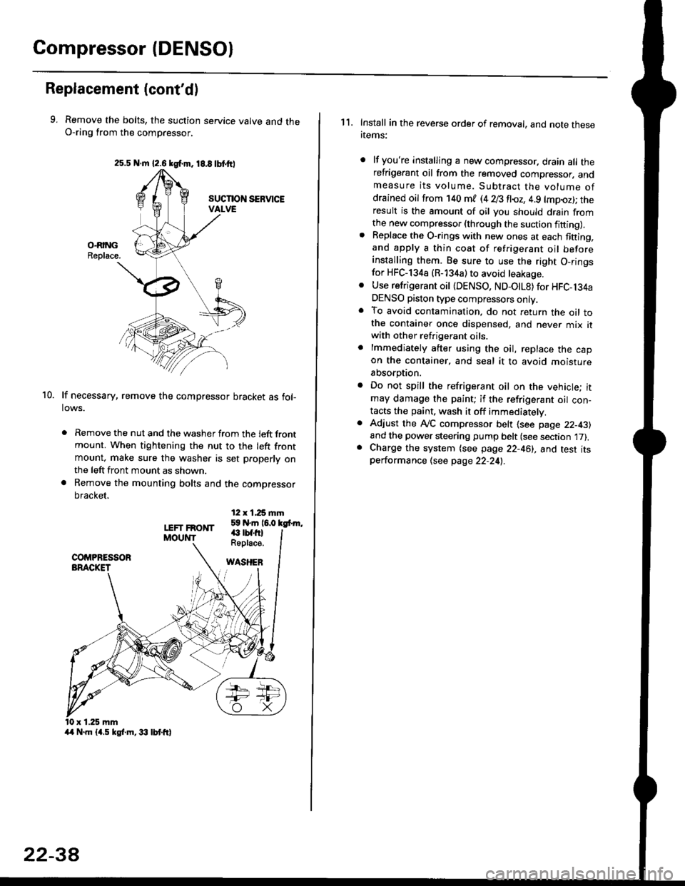
9. Remove the bolts, the suction service valve and theO-ring from the compressor,
lf necessary, remove the compressor bracket as fol-lows.
. Remove the nut and the washer from the left frontmount. When tightening the nut to the left frontmount, make sure the washer is set p.operly onthe left front mount as shown.
a Remove the mounting bolts and the compressor
bracket.
12 x 1,25 rnm59 N.m 16.0 kgfrm,
10.
LEFT FRONTMOUNT€ rbf.fi)Roplace.
WASHEB
x 1.25 mm
2s.5 N.m {2.6 kgf.m. 18.8 tbtttl
4/r N.m {4.5 kgf.m, 33 lbt ft}
22-3A
1 1. Install in the reverse order of removal, and note thesertems:
lf you're installing a new compressor. drain all therefrigerant oil from the removed compressor. andmeasure its volume. Subtract the volume ofdrained oil from '140 ml (4 28 fl{,z, 4.9 lmpoz); theresult is the amount of oil you should drain fromthe new compressor (through the suction fifting).Replace the O-rings with new ones at each fining,and apply a thin coat of refrigerant oil beforeinstalling them. Be sure to use the right O,ringsfor HFC-134a (R-134a) to avoid leakage.
Use refrigerant oil {DENSO, ND-OtL8) for HFC-134aDENSO piston type compressors only.To avoid contamination, do not return the oil tothe container once dispensed, and never mix itwith other refrigerant oils.
lmmediately after using the oil, replace the capon the container, and seal it to avoid moisture
absorption.
Do not spill the refrigerant oil on the vehicle; itmay damage the paint; if the refrigerant oil con-tacts the paint, wash it off immediatelv.
Adjust the ly'C compressor belt (see page 22-43)and the power steering pump belt (see section 17).Charge the system (see page 22-46), and test itsperformance (see page 22-24!..
Page 1467 of 2189
A/G GomPressor Belt
Adjustment
Detlection Method
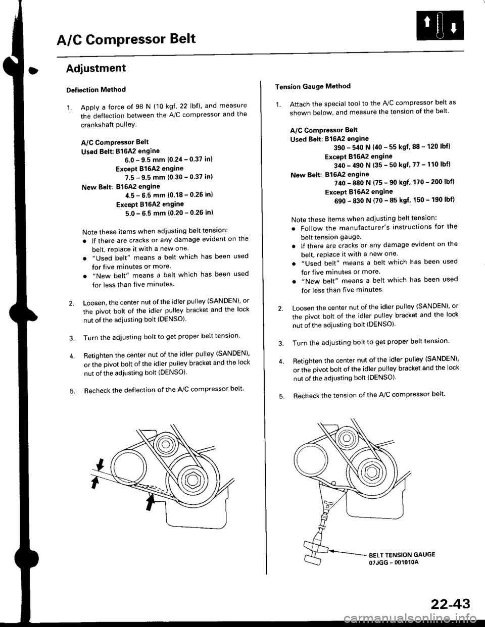
'1. Apply a force of 98 N (10 kgf, 22 lbf), and measure
the deflection between the A,/C compressor and the
crankshaft PulleY
A/C ComPressor Belt
Used Belt: 816A2 engine
6.0 - 9.5 mm 10 2'l - 0.37 inl
Except 816A2 engine
7.5 - 9.5 mm (0.30 - 0.37 in)
New Belt: 816A2 engine
4.5- 6 5 mm (0.18-0.26 in)
Except 815A2 engine
5.0-5 5 mm (0.20-0.26 inl
Note these items when adjusting belt tens'on:
. lf there are cracks or any damage evident on the
belt, replace it with a new one.
. "Used belt" means a belt which has been used
for five minutes or more.
. "New belt" means a belt which has been used
tor less than five minutes.
2. Loosen, the center nut ofthe idler pulley (SANDEN), or
the pivot bolt of the idler pulley bracket and the lock
nut ofthe adjusting bolt (DENSO).
3. Turn the adjusting bolt to get proper belt tension'
4. Retighten the center nut of the idler pulley (SANDEN),
or the pivot bolt of the idler pulley bracket and the lock
nut of the adjusting bolt (DENSO).
5. Recheck the deflection of the A,/C compressor belt'
Tension Gauge Method
1. Attach the special tool to the IVC compressor belt as
shown below, and measure the tension of the belt
A/C Compressor Belt
Used Belt: 816A2 engine
390 - 540 N (40 - 55 kgf, 88 - 120 lbll
Except 816A2 engine
340 - 490 N (35 - 50 ksf, 77 - 110 lbfl
New Belt: B16A2 engine
?40 - 880 N {75 - 90 ksf' 170 - 200 lbf)
Except Bl642 engine
690 - 830 N (70 - 85 ksf, 150 - 190 lbf)
Note these items when adjusting belt tension:
. Follow the manufacturer's instructions for the
belt tension gauge.
. lf there are cracks or any damage evident on the
belt, rePlace it with a new one.
. "Used belt" means a belt which has been used
for five minutes or more.
. "New belt" means a belt which has been used
for less than five minutes
2 Loosen the center nut of the idler pulley (SANDEN)' or
the pivot bolt of the idler pulley bracket and the lock
nut of the adjusting bolt (DENSO).
3. Turn the adjusting bolt to get proper belt tension
4. Retighten the center nut of the idler pulley (SANDEN),
or the pivot bolt of the idler pulley bracket and the lock
nut of the adjusting bolt (DENSO)
5. Recheck the tension of the A/C compressor belt'
22-43
Page 1468 of 2189
Condenser
Replacement
1.Recover the refrigerant with a recovery/recycling/
charging station lsee page 22-271.
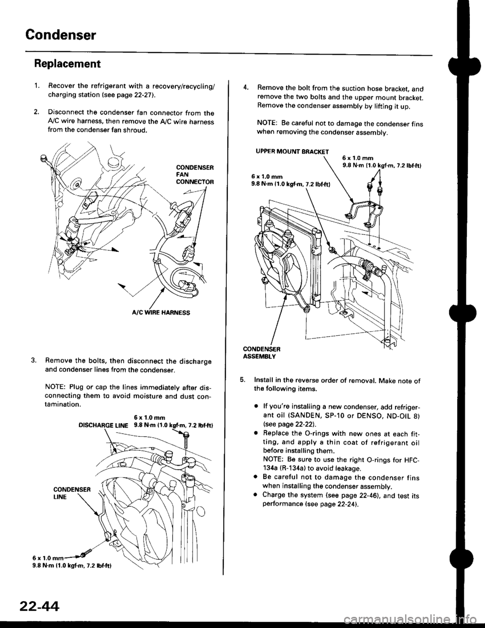
Disconnect the condenser fan connector from theAy'C wire harness, then remove the A,/C wire harnessfrom the condenser fan shroud.
Remove the bolts, then disconnect the dischargeand condenser lines from the condenser.
NOTE: Plug or cap the lines immediately after dis-connecting them to avoid moisture and dust con-tamination,
6r1.0
6x1.0mmolscHARGE L|NE 9.8 N.m 11.0
9.8 N.m 11.0 kgl.m, 7.2 lbf.ftl
22-44
4. Remove the bolt from the suction hose bracket, andremove the two bolts and the upper mount bracket.Remove the condenser assembly by lifting it up.
NOTE: Be careful not to damage the condenser finswhen removing the condenser assembly.
UPPER MOUNT BRACKET
5. Install in the reverse order of removal. Make note ofthe following items.
. lf you're installing a new condenser, add refriger-ant oil (SANDEN, SP-10 or DENSO, ND-O|L 8)
\see page 22-22l.-
. Replace the O-rings with new ones at each fit-ting, and apply a thin coat of refrigerant oilbefo.e installing them.
NOTE; Be sure to use the right O-rings for HFC,134a (R-134a) to avoid leakage.o Be careful not to damage the condenser finswhen installing the condenser assembly.. Charge the system (see page 22-46), and test itsperformance (see page 22-24i.
6x1.0mm9,8 N.m 11.0 kg{.m, 7.2lbtft}
6x1.0mm9.8 N.m 11.0 kst m, 7.2 lbf.ftl
Page 1473 of 2189
Troubleshooting
ll.
Tips and Precautions
Bef ore Troubleshooting
. Check applicable fuses in the appropriate fuse/relay
box.
. Check the battery for damage, state of charge, and
clean and tight connections.
. Check the alternator belt tension.
CAUTION:
. Do not quick-charge a battery unless the battery
ground cable has been disconneqted, otherwise you
will damage the alternator diodes.
. Do not attempt to crank the engine with the battery
ground cable loosely connecled or you will severely
damage the wiling,
Handling Connectois
. Make sure the connectors are clean and have no loose
wire terminals.
. Make sure multiple cavity connectors are packed with
grease (except watertight connectors)
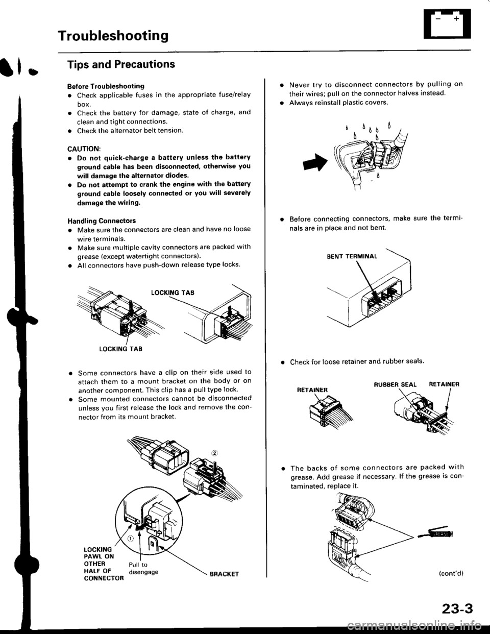
. All connectors have push-down release type locks.
Some connectors have a clip on their side used to
attach them to a mount bracket on the body or on
another component. This clip has a pulltype lock.
Some mounted connectors cannot be disconnected
unless you first release the lock and remove the con-
nector from its mount bracket.
LOCKINGPAWL ONOTHERHALF OFCONNECTOR
Pull todrsengage
LOCKING TAB
BRACKET
Never try to disconnect connectors by pulling on
their wires; pull on the connector halves instead
Alwavs reinstall plastic covers.
Before connectang connectors,
nals are in place and not bent.
make sure the terml-
. Check for loose retainer and rubber seals.
RETAINER
The backs of some connectors are packed with
grease. Add grease if necessary. lf the grease is con-
taminated, replace it.
(cont'd)
23-3